UNIVERSITI TEKNIKAL MALAYSIA MELAKA
BORANG PENGESAHAN STATUS LAPORAN PROJEK SARJANA MUDA
TAJUK: Mechanical properties determination of mild steel and stainless steel joint fabricated by MIG welding process
SESI PENGAJIAN: 2009/10 Semester 2
Saya SHAHRIR BIN SAHARI
mengaku membenarkan Laporan PSM ini disimpan di Perpustakaan Universiti Teknikal Malaysia Melaka (UTeM) dengan syarat-syarat kegunaan seperti berikut:
1. Laporan PSM adalah hak milik Universiti Teknikal Malaysia Melaka dan penulis. 2. Perpustakaan Universiti Teknikal Malaysia Melaka dibenarkan membuat salinan
untuk tujuan pengajian sahaja dengan izin penulis.
3. Perpustakaan dibenarkan membuat salinan laporan PSM ini sebagai bahan pertukaran antara institusi pengajian tinggi. atau kepentingan Malaysia yang termaktub di dalam AKTA RAHSIA RASMI 1972)
(Mengandungi maklumat TERHAD yang telah ditentukan oleh organisasi/badan di mana penyelidikan dijalankan)
Alamat Tetap:
DECLARATION
I hereby, declared this report entitled “Mechanical properties determination of mild steel and stainless steel joint fabricated by MIG welding process
” is the results of my own research except as cited in references
Signature : ……….
Author’s Name : ……….
Date : ……….
APPROVAL
This report is submitted to the Faculty of Manufacturing Engineering of UTeM as a partial fulfillment of the requirements for the degree of Bachelor of Manufacturing Engineering (Manufacturing Process) with Honours. The member of the supervisory committee is as follow:
(Signature of Supervisor)
……..………
ii
ABSTRAK
i
ABSTRACT
iv
ACKNOWLEDGEMENTS
v
2.1.1 Typical Stainless Steel Application 10
2.1.2 Austenitic (200 and 300 series) 11
2.2 Low Carbon Steel (Mild Steel) 12
2.2.1 Typical Mild Steel Application 12
vi
2.3.1 MIG Metal Transfer 14
2.3.1.1 Spray Transfer 14
2.3.1.2 Globular Transfer 15
2.3.1.3 Short Circuiting Transfer 15
2.3.2 MIG Equipment Setup 16
2.3.3 Principles of Operation 17
2.4 Dissimilar Metal Welding 18
2.4.1 Weld Metal 18
2.4.2 Dilution 19
2.4.3 Melting Temperature 19
2.4.4 Thermal Conductivity 19
2.4.5 Coefficient of Thermal Expansion 19
2.5 Welding Stainless Steel and Mild Steel 20
2.6 Welding Consideration 20
2.6.1 Filler Wire Selection for Dissimilar Metal 20
2.6.2 Buttering Process 22
2.6.3 Joint Design for MIG 23
2.6.4 Butt Joint 23
2.6.5 Shielding Gas 24
2.7 Variation for MIG welding Process 25
2.8 Mechanical Properties 25
2.11 Weldment Microstructure 30
vii
3.3 Equipment preparation 37
3.4 Design of Experiment (D.O.E) 38
3.4.1 Determine MIG welding Settings 38
3.4.2 Procedure of Hardness Measure 39
3.5 Machine Setup 40
3.6.3 Buttering Process 42
3.6.4 Tack Weld process 43
3.6.5 Welding process 43
3.7 Specimen Preparation 44
3.7. 1 Cutting process 45
3.7.2 Tensile Specimen (ASTM E8) 45
3.7.3 Hardness Specimen (ASTM 10) 46
3.7.4 Microstructure Specimen (ASTM E3) 47
3.7.5 Impact Specimen (ASTM E23) 48
3.8 Experimentation 48
3.8.1 Hardness Test Measurement 49
3.8.2 Tensile Test Measurement 49
3.8.3 Impact Test Measurement 50
viii CHAPTER 4: RESULT AND DISCUSSION
4.1 Hardness Result-D.O.E 53
4.2 Actual Experiment 56
4.3 Hardness Result 56
4.3.1 Hardness Data Analysis 57
4.4 Results for Tensile Test 59
4.4.1 Data Collected Analysis 60
4.4.2 Stress versus Strain Analysis 61
4.5 Results for Charpy Impact 63
4.6 Results for Microstructure Analysis 64
ix
2.4 Short-circuiting transfer. 16
2.5 Schematic of equipment setup for MIG 16
2.6 Illustration operation of MIG 17
2.7 Effect of electrode position and welding technique. 17 2.8 A Schaeffler diagram and the procedure of estimating the 21
microstructure of E309-type.
2.9 Buttering process used to assist in dissimilar welding 22 2.10 Bevel angle, groove angle, and root opening of joints for welding. 23 2.11 Shielding gas related to weld profile for DCEP 24
2.12 Diagram of tensile test machine 26
2.13 Typical stress-strain curve obtained from tensile test. 27
2.14 Rockwell hardness testing technique. 29
2.15 Charpy-V notch impact apparatus. 30
2.16 Optical microstructure of parent metal Austenite 304 stainless steel. 31 2.17 Optical microstructure of parent metal plain mild steel. 31 2.18 Heat affected zone microstructure Austenitic steel side. 31
2.19 Anatomy of a weld. 32
3.1 Process Flow Chart 35
3.2 Stainless steel plate 36
3.3 Mild Steel Plate 36
3.4 Filler Wire specification 37
x
3.6 Hardness measured point for D.O.E purpose 39
3.7 Hardness test in progress 39
3.8 Show the sequence to install the filler wire 40
3.9 Procedure to change the MIG contact tip 41
3.10 Beveling process. 42
3.11 Buttering process at AISI 1010 side 42
3.12 Allocated the tack weld. 43
3.13 MIG welding in action 43
3.14 Finish welded part with 45 degree single groove butt join type 44
3.15 The way specimen cut from weld part 44
3.16 Cutting the specimen for testing 45
3.17 Standard specimen for tensile test 45
3.18 Tensile specimen for 1.2 mm diameter filler wire 46
3.19 Example of hardness test specimen 46
3.20 Hardness test specimens 47
3.21 Metallographic specimens. 47
3.22 Specimen for charpy impact test 48
3.23 Rockwell hardness machine 49
3.24 Hardness test process 49
3.25 Tensile machine in progress 50
3.26 Impact Tester 51
3.27 Specimen with before and after impact test 51
3.28 Image Analyzer (Buehler Omniment). 52
3.29 Grinding and polishing equipment (Buehler). 52
4.1 Hardness Result for 1.2 mm filler wire 53
4.2 Hardness Result for 0.8 mm filler wire 54
4.3 Hardness measure point 54
4.4 Mean of hardness value on dissimilar metal joint. 57
xi
4.6 Properties comparison between different size filler wire. 60
4.7 Result tension test for specimen A 61
4.8 Result tension test for specimen F 62
4.9 Show the Result obtain from Charpy test 63
4.10 Physical appearance of the specimen after the test 63
4.11 Metallographic observation on 1.2 mm (20 X) 64
4.12 Metallographic observation on 0.8 mm (20 X) 65
4.13 Heat Affected zone (HAZ) and weldment 66
xii
LIST OF TABLES
2.1 Minimum Mechanical Properties for annealed Alloys 11 2.2 Nominal Compositions of Austenitic Stainless Steels. 11 2.3 Mechanical properties of selected carbon steel. 12
2.4 Composition of selected carbon steel. 12
2.5 The nominal chemical compositions of the alloy steel 21
2.6 Mechanical properties of ER309 21
2.7 Recommended parameter for MIG using welding grade CO2 22
2.8 The variation of the MIG welding process. 25
2.9 Recommended etching solution for dissimilar metal 32
3.1 General setting parameter for MIG welding process 38
3.2 Best Parameter for Welding machine MIG 210S 40
3.3 Standard specimen size for tensile experiment (From ASTM E8) 46
3.4 Parameter for Hardness test machine 49
3.5 Parameter for tensile test machine 50
4.1 MIG parameter for 1.2 mm filler wire 55
4.2 MIG parameter for 0.8 mm filler wire 55
4.3 Specimen number for each filler wire 56
4.4 Convert HRB value to approximate tensile strength 58 4.5 Data of tensile test using 1.2 mm and 0.8 mm MIG filler wire 60
xiii
LIST OF ABBREVIATIONS
AWS - American Welding Society
AISI - American Iron and Steel Institute
ASTM - American Standard Testing for Material
ASME - American Society of Mechanical Engineer
BHN - Brinell Hardness Number
Cr - Chromium
CV - Constant Voltage
CO2 - Carbon dioxide
DCEP - Direct Current Electrode positive
DCEN - Direct Current Electrode Negative
GTAW - Gas Tungsten Arc Welding
GMAW - Gas Metal Arc Welding
HAZ - Heat Affected Zone
MIG - Metal Inert Gas
Mn - Manganese
Ni - Nickel
PSM - Projek Sarjana Muda
SMAW - Shield Metal Arc Welding
SAW - Submerge Arc Welding
1
CHAPTER 1
INTRODUCTION
1.1 Introduction
Welding is very common technique in order to join two or more types of metal. Welding is used to join all commercial metals and alloys and to joint metal of different type of strength. Welding begin as a repair or maintenance tool and has become one of the most crucial manufacturing methods as well as the most essential construction method. Almost everything made of metal is welded. Because of its strength and versatility, welding is used in manufacture of almost all the products used in our life every day. Without welding many community cannot afford the cost of the goods and services they need to earn a living (Cary & Helzer, 2005).
2
For an example, the famous trans-Alaska pipeline, a super-tanker, the world largest moving weldment, storage tank for water supply systems, the sears Tower in Chicago would not be possible without welding. The international space station was welded together on earth and transported to space, and the final assembly welds were done in space. The shuttle itself, from the rocket engines to the external fuel tank, required specialized procedures for welding alloy aluminum without defects. Most large airplanes include much welding, even miniature components for electronic equipment and telecommunication equipment. All of these prove that welding is important in many applications (Cary & Helzer, 2005).
3
1.2 Project Background
Welded dissimilar metal joints become widely accepted as the superior design option for manufactured products between their quality, reliability, and serviceability. The welding industries are working to remove reservations in areas where there is concern about welded joints due to limitations of materials, process, and ability to ensure quality. In the recent years, welding dissimilar metal joint promotes various service conditions such as resistance to corrosion, heat resistance and magnetic properties. A lot of study has been done with the dissimilar welding technology nowadays.
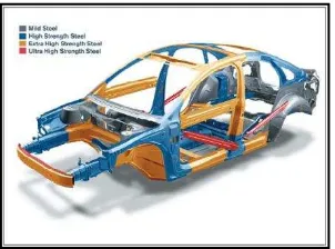
Wagner et al. (2000) shows there were a lot of wide variety of possible applications for dissimilar material combinations. At present, the main focus in this area is aiming car body concepts for weight reduction and higher stiffness due to the locally use of aluminum sheet materials. For power train components the combination of aluminum parts with thin walled steel pipes offers the opportunity for a significant reduction of the rotating masses. Under this concern, higher product efficiency could be realized.
Figure 1.0: Dissimilar metal joint in Volvo S40 (Available at: http://www.designnews.com).
4
1.3 Problem Statement
Weld between dissimilar metals relates to the transition zone between the metal and the intermetallic compounds formed in this transition zone. For the fusion welding processes, it is important to investigate the composition of two metals involved. If there is mutual solubility of the two metals, the dissimilar joint can be made successfully. If there is little or no solubility between the two metals to be joined, the weld joint will not be successful (Cary & Helzer, 2005).
Al Wadleigh (1991) derive dissimilar metals have different chemistries, so they have different physical properties such as melting temperature. Many who have involved with joining metal with different melt temperature experience frustration. The difficulties was arise when someone try to melt metal together at same weld temperature. For example mild steel and stainless steel, obviously in nature these materials have different melting point.
MIG welding is widely used in many industry applications such as automotive, oil and gas, agriculture, and construction. Their versatility, rapid, economical, capable in all weld position, technique, speed and high deposition is the reason why it most used. MIG welding can operate with semiautomatic or automatic and work with most metal (Kalpakjian & Schmid, 2006).
5
Kiling (2001) stated that scope of application of MIG welding in German is over 75% nowadays, it is being used in partial mechanized, fully mechanized and automate technique. MIG welding produce high quality weld at high speed without the used flux and limited postweld cleaning. It is very desirable for both small and high production metal joining. It frequently replaces other joining process such as riveting, brazing, silver-soldering, or resistance welding. MIG welding is better than friction welding in term of flexibility because friction welding constraint for round billet shape or pipe only. It may be used instead of the following fusion welding process; submerge arc welding, flux core and gas tungsten arc welding.
However material such Mild steel and stainless steel are widely used in many applications such as construction, power plant, petrochemical, offshore, and more. Mild steel is low carbon steel that easy to form and has excellent weldability meanwhile stainless steel has popular as resistant to corrosion material and weldable with various application (Kalpakjian & Schmid, 2006).
6
1.4 Objective
The objectives of the research are as follow:
a) To study the effect on mild steel and stainless steel joint using different diameter filler wire of MIG welding.
b) To evaluate weld properties through the Hardness, Tensile, and Microstructure.
c) To analyze the characteristic of weldment and heat affected zone (HAZ) microstructure.
1.5 Scope of Project
7
1.6 Report Organization
Chapter 1: Introduction
a) This chapter briefly explained the background of the project study, the objective that want to achieved, the problem statement and finally whole project planning through Gantt chart.
Chapter 2: Literature Review
a) This chapter was collection of research information that relate to the study from any trusted resources.
Chapter 3: Research Methodology
a) This chapter explains the structure on how project was done
Chapter 4: Result and Discussion
a) The output from the study was precisely explain and discussed in this chapter.
Chapter 5: Conclusion and Recommendation
a) This chapter finally explains the achievement of whole project to compare with objectives.
1.7 Project Planning