International Conference and Exhibition on Sustainable Energy and Advanced Materials (ICE SEAM 2011) Solo-Indonesia. October 3-4, 2011.
258
|
I C E S E A M 2 0 1 1
Welding Current Effect on Mechanical Properties of Spot Welded
Dissimilar Metals between Stainless Steel J4 and Low Carbon Steel
Agustinus Eko Budi Nusantara
1),*, Triyono
1), Kuncoro Diharjo
1)1)
1Mechanical Engineering Department, Sebelas Maret University,Surakarta, INDONESIA * Corresponding author. E-mail: [email protected], [email protected]
Abstract
Low nickel stainless steel has been developed as a replacement for conventional stainless steel because it is cheap and environmentally friendly. Due to economic reasons, spot welded dissimilar metals between stainless steel J4 and low carbon steel have been conducted. It is generally more challenging than that of similar materials due to differences in the physical, chemical and mechanical properties of the base metals. In this study, the influence of the current on the morphology, microhardness, and tensile shear load bearing capacity of it has been investigated. Stainless steel J4 and low carbon steel with thicknesses of 1.2 mm were spot welded using the current of 4kA, 6kA and 8kA. The increasing of welding current increased the nugget size and tensile-shear load bearing capacity of the joint. It also changed the interfacial failure to pull out failure.
Keywords: dissimilar metals weld, resistance spot welding, stainless steel, low carbon steel
1.
Introduction
The resistance spot welding is much applied in industries, particularly those using the sheet metal as the raw material, such as the automotive industry. One of the advantages of the technique of the resistance spot welding is its ability to be applied to various kinds of metal within a relatively short process cycle. The resistant spot welding (RSW) itself is a sufficiently complex cycle which involves electric, heat, and mechanical interactions as well as metallurgical phenomenon and each process parameter will have effect on the quality and the properties of the welding result.
If the resistance spot welding is used to join two dissimilar metals, then the phenomena that occur will be more complex in relation to the basic properties of each of the base metals.
The problem that frequently emerges in the resistance spot welding of dissimilar metals, particularly that of carbon steel and stainless steel, is the decline of the corrosion resistance which has an effect on the mechanical property in such a way that the catastrophic failure will occur easily.
The objective of previous research on the joint of both of the similar and the dissimilar metals, particularly the dissimilar metals (carbon steel and stainless steel) by using the RSW technique is to investigate the effect of the parameter of the welding on its mechanical property, corrosion resistance, and micro structure as well.
Triyono et al. in 2005 conducted a research on the effect of flame heating in omitting the residue tension of the welding of stainless steel (SS) to carbon steel (CS). The residue tension of the welding as a result of the heating and the cooling of the dilution area and the heat-affected zone (HAZ) has an effect on the resistance of phatic fracture and stress corrosion cracking (SCC). However, the treatment of flame heating inflicts a loss if seen from its thermal cycle since it can decrease its stainless steel corrosion resistance so that it is necessary to investigate the best technique of omitting residue tension.
The stainless steel material is the type of material which has good strength, resilience, toughness, and formability characters. It has face-centered cubic (FCC) crystal structure. This crystal structure is formed due to an addition of the austenite alloying elements, such as nickel, manganese, and nitrogen. This material is not magnetic in its annealing condition and can only be hardened by using the cold working technique. This material has good corrosion resistance property, good weld ability, and high strength. The right choice of welding technique becomes important in maintaining its mechanical property.
International Conference and Exhibition on Sustainable Energy and Advanced Materials (ICE SEAM 2011) Solo-Indonesia. October 3-4, 2011.
259
|
I C E S E A M 2 0 1 1
The RSW technique is classified into the electric resistance welding and it is the simple welding technique. It is also frequently used. In using the RSW technique, four welding cycles are known:
a. Squeeze time, which is the time interval between providing the initial force (pressing) on the base metal and providing current,
b. Weld time, which is the time interval between providing current to the object and the compressive force of constant electrode,
c. Hold time, which is the time in which the constant electrode force is provided to the welding spot (nugget) but the current not any longer flows and the nugget is clotted until it has sufficient strength,
d. Off time, which is the time when the electrode does not any longer work on the spot and it is ready to work on another welding spot.
In using the RSW the metal that is being joined has the form of sheets in general and the sheets are composed in the lap joint and the butt joint configurations. Both of the metal sheets are pressed to one another by using electrode and at the same time the electric current is flowed so that the surface in contact with the electrode becomes heated due to the electric resistance and then the surface gets melted. Then, this melted metal is cooled in the effect of pressure so that sufficient power is gained to join two sheets welded. The density of the current and the pressure that are provided are in such a way that nugget is formed. The shear strength of the nugget in general has to be sufficient to ensure that the sheets surrounding the nugget are broken off if the joint is stressed until it is broken off as well.
2.
Methodology
The welding of the stainless steel of J4 type to the carbon steel each with 1.2-mm thickness, with the various current levels of 4kA, 6kA, and 8kA, with 2.5-scond weld, and by using the RSW technique, was done in order to investigate the effect of the strength of the electric current on the mechanical property of the joint. The joint was made in the lap joint configurations.
The materials which were used in this research were the carbon steel and the stainless steel of J4 type each with the following chemical composition:
Table 1. Carbon steel with chemical composition as follows: (wt%)
C% Si% Mn% P% S% Al% Cu%
0.022 0.014 0.721 0.022 0.019 0.033 0.013
Table 2. Stainless Steel (of J4 type) with chemical composition in accordance with Jindai Steel (wt%)
C% Mn% S% P% Si% Ni% Cr% Cu% N%
0.095 9.25 0.005 0.065 0.35 1.05 15.30 1.75 0.13
The Resistance Spot Welding which was used had the Rated Power of 16kVA, the Alterating Current of the main input of 380V, the Rated input current of 42A, and the empty load voltage which ranged from 1.6 V up to 3.2 V (6 stages). The shear testing was done by using the Universal Testing Machine on all specimens by having the AWS as the reference in order to investigate the mechanical property of the joint of the two materials, the optimum joint spot, and the effect on the shear strength.
International Conference and Exhibition on Sustainable Energy and Advanced Materials (ICE SEAM 2011) Solo-Indonesia. October 3-4, 2011.
260
|
I C E S E A M 2 0 1 1
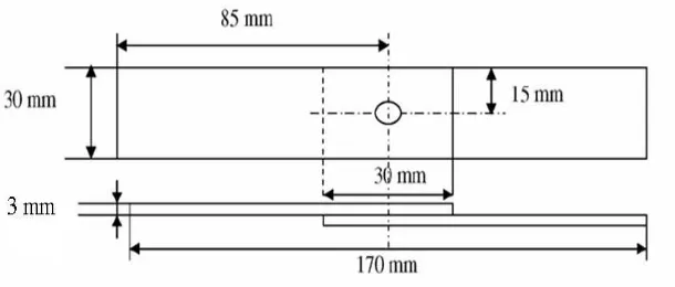
Figure 2. Photograph of Shear Test Specimen
Tensile-shear testing was done in order to find out the mechanical property of the joint. The dimension of the Peak Load and the Failure Energy in which this Failure Energy was obtained through calculating the dimension of the area under the curve of the Load Displacement diagram could also be known through the tensile-shear testing.
Figure 3. Load Displacement Diagram
The joint failure model can be found out by observing the result of the specimen testing. The hardness testing was done by using the Vickers method, the macro structure testing, and the micro structure testing with the optical microscope.
3.
Results and Discussion
The results of the mechanical testing, the macro structure testing, and the micro structure testing are shown by the following figures and diagram. The results of the tensile - shear strength of the specimens which were respectively welded with the welding current strengths of 4kA, 6kA, and 8kA as well as the magnitude of the Peak Load which was the factor to the joint failure can be seen in the Load Displacement diagram as follows:
International Conference and Exhibition on Sustainable Energy and Advanced Materials (ICE SEAM 2011) Solo-Indonesia. October 3-4, 2011.
261
|
I C E S E A M 2 0 1 1
Failure energy is obtained by calculating the dimension of the area under the curve of the load displacement diagram. The difference in the failure energy is caused particularly by the difference in the size of the nugget shown by the following table:
Table 3. Correlation between Welding Current Strength and Size of Nugget
Specimen Welding Current (kA) Diameter of Nugget (mm)
Specimen I 4 3.6
Specimen II 6 5.4
Specimen III 8 7.1
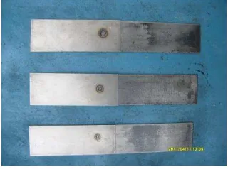
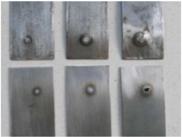
The failure model of the joints of the welding spot resistant can be found out from the observation on all specimens after the shear and tensile testing. Specimens I and II fail in the nugget (interfacial failure) whereas specimen III which was welded with the welding current strength of 8kA fails in the HAZ (Heat Affected Zone) or around the nugget (pull-out failure) of the J4 material. This can be explained by observing the changes of the micro structure and the phases which occur in the weld metal and the HAZ and results in the change in the mechanical property.
Figure 5. Fracture models; (a) and (b) interfacial failure; (c) pull-out failure
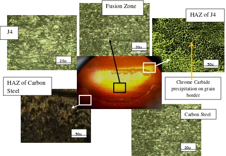
According to Triyono et al. (2010), the problems in the welding of the austenitic stainless steel are the decline in the corrosion resistance and in the mechanical property as well as the embrittlement due to the formation of precipitate of the chrome carbide which precipitates between the austenite grain borders. This subtle precipitation can be formed due to the slow cooling from the temperature of 900o down to 450o. On the other hand, carbon steel will be hardened in its HAZ if the cooling rate at the time of welding is sufficiently high in such a way that fracture can occur.
International Conference and Exhibition on Sustainable Energy and Advanced Materials (ICE SEAM 2011) Solo-Indonesia. October 3-4, 2011.
262
|
I C E S E A M 2 0 1 1
The results of hardness test by using the Vickers method are as follows:
SS J4 HAZ J4
Figure 6. Diagram of Hardness and Location of Indentation Point of Specimen I
Figure 7. Diagram of Hardness of Specimen II
International Conference and Exhibition on Sustainable Energy and Advanced Materials (ICE SEAM 2011) Solo-Indonesia. October 3-4, 2011.
263
|
I C E S E A M 2 0 1 1
Figure 8. Diagram of Hardness of Specimen III
Out of all diagrams on hardness above, the hardness of the nugget and the HAZ of the material of carbon steel of specimens I and II are greater than those of J4 since each of both materials undergoes heterogeneous
Figure 9. Macro and micro structure of joint
International Conference and Exhibition on Sustainable Energy and Advanced Materials (ICE SEAM 2011) Solo-Indonesia. October 3-4, 2011.
264
|
I C E S E A M 2 0 1 1
One of the phenomena which occur on the weld at all current strength levels is that there is a very clear-cut border between the weld metal and the base metal of carbon steel. However, this phenomenon does not occur on the SS J4 side since the stainless steel of J4 has much higher thermal and electric conductivities. According to Mehdi Mansouri et al. (2010), stainless steel has the electric conductivity of 72 µΩ cm whereas carbon steel only
has 12 µΩcm.
Figure 10. Border between weld metal and base metal of carbon steel (augmentation by 100 times)
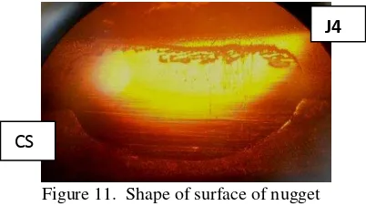
The heterogeneity in the thermal and the electric conductivities also causes the shape of the surface of the nugget to be asymmetrical. The dimension of the nugget in the direction to its J4 side is greater than that in the direction to its carbon steel side.
Figure 11. Shape of surface of nugget
The transformation of the micro structure of the weld by using RSW is very much dependent on the chemical composition of the base metal and the welding parameter. According to Mehdi Mansouri Abadi Hasan, the most optimum parameters of the welding of dissimilar metals are as follows:
The size of nugget becomes an important standard in investigating the mechanical property of a joint. Greater size of the nugget indicates greater strength. The size of nugget is very much dependent on the heat input whereas the heat input is dependent on the strength of the welding current. Greater welding current and greater welding time will result in greater size of the nugget.
The heat input also has an effect on the indentation depth of the electrode. The indentation depth of the
electrode is dependent on the compressive force of the electrode. The electrode’s indentation which is too
deep will in point of fact decrease the quality of the nugget. This is proven by specimen III which underwent reduced hardness and cavity in the middle of the nugget after it was welded by using the highest welding strength level (8kA). Therefore, the indentation depth of the electrode will better be maintained at the minimum point.
If the weld with the failure model of pull-out type is obtained, then the failure does not occur on the nugget but on the base metal. Finding out the quality of the joint resulted from RSW by using the tensile – shear strength is the easiest way to do.
The chrome carbide in the HAZ of J4 metal is maintained at the minimum level. The increase in the strength of the welding current will increase the risk of the formation of chrome carbide precipitation.
4.
Conclusion
From the test on the joint which resulted from the welding of the dissimilar metals of carbon steel and stainless steel of J4 type, conclusions are drawn:
Border
J4
International Conference and Exhibition on Sustainable Energy and Advanced Materials (ICE SEAM 2011) Solo-Indonesia. October 3-4, 2011.
265
|
I C E S E A M 2 0 1 1
1. Higher strength of electric current for welding results in greater size of nugget and higher tensile – shear strength. In addition, a change in the failure model from interfacial fracture into pull-out fracture in the HAZ of the material of J4 is due to the embrittlement of the zone as a result of the formation of the chrome carbide on the grain border.
2. On the specimen that is welded by using the highest electric current (8kA), the nugget has the relatively homogeneous hardness on both sides of J4 and carbon steel. On the other hand, the nugget will have heterogeneous hardness between the sides of J4 and carbon steel if the specimen is welded by using the current strength of 4kA and 6kA.
3. Due to the difference in the thermal and the electric conductivities of both materials, the nugget that is formed is asymmetrical. The extent of the nuggest in the direction to the side of J4 is greater than that in the direction to the side of carbon steel
References
ASM Hand Book volume 6, (1992), Welding Brazing and Soldering, ASM International,684-692.
Koos Sardjono KP, (2001), Pengaruh Masukan PanasPada sambungan Las ERW terhadapKekerasan Material Pipa Baja API 5L-GR.B(Diameter 10” dan Tebal 9.30mm),Jurnal Teknologi Industri Vol.V No.1 Januari 2001.
Mehdi Mansouri Hasan Abadi, Majid Pouranvari, (2010), Correlation Between Macro/Micro Structures and Mechanical Properties of Dissimilar Resistant Spot Welds of AISI 304 Austenitic Stainless Steel and AISI 1008 Low Carbon Steel, [email protected] 2011.
Triyono,Diharjo K,Ilman Nur & Soekrisno, (2008), Pengaruh Flame Heting Terhadap Ketahanan Korosi dan sifat Mekanis Sambungan Las Logam Tak Sejenis Pada Struktur Utama Gerbong Kereta Api,Http:/fadli080284.web44.
Wiryosumarto H, Akumura T , Teknologi Pengelasan Logam, PT. Pradnya Paramita,Jakarta.