UNIVERSITI TEKNIKAL MALAYSIA MELAKA
A STUDY OF EFFECTS OF MACHINING PARAMETERS ON
SURFACE ROUGHNESS IN END MILLING
This report submitted in accordance with requirement of the Universiti Teknikal Malaysia Melaka (UTeM) for the Bachelor Degree of Manufacturing Engineering
(Manufacturing Process) with Honours.
by
NOR KAMARIAH BT MOHAMAD KHALID
UTeM Library (Pind.1/2007)
UNIVERSITI TEKNIKAL MALAYSIA MELAKA
BORANG PENGESAHAN STATUS LAPORAN PROJEK SARJANA MUDA
JUDUL: STUDY OF EFFECTS OF MACHINING PARAMETERS ON SURFACE ROUGHNESS IN END MILLING
SESI PENGAJIAN : 2009/2010 Semester 2
Saya NOR KAMARIAH BINTI MOHAMAD KHALID
mengaku membenarkan Laporan PSM ini disimpan di Perpustakaan Universiti Teknikal Malaysia Melaka (UTeM) dengan syarat-syarat kegunaan seperti berikut: 1. Laporan PSM adalah hak milik Universiti Teknikal Malaysia Melaka dan penulis. 2. Perpustakaan Universiti Teknikal Malaysia Melaka dibenarkan membuat salinan
untuk tujuan pengajian sahaja dengan izin penulis.
3. Perpustakaan dibenarkan membuat salinan laporan PSM ini sebagai bahan pertukaran antara institusi pengajian tinggi. atau kepentingan Malaysia yang termaktub di dalam AKTA RAHSIA RASMI 1972)
(Mengandungi maklumat TERHAD yang telah ditentukan oleh organisasi/badan di mana penyelidikan dijalankan)
(TANDATANGAN PENULIS)
ii
DECLARATION
I hereby, declared this report entitled “Study of Effects of Machining Parameters on Surface Roughness in End Milling” is the results of my own research except as cited in
references.
Signature : ………..
iii
APPROVAL
This PSM submitted to the senate of UTeM and has been as partial fulfillment of the requirements for the degree of Bachelor of Manufacturing Engineering (Manufacturing
Process). The member of the supervisory committee is as follow:
……… Dr. Mohd Rizal Bin Salleh
iv
ABSTRACT
v
ABSTRAK
vi
DEDICATION
This study is dedicated to my beloved parents, Mohamad Khalid Bin Abdullah and
Kamsiah Binti Jalil.
vii
ACKNOWLEDGEMENT
viii
1.5 Organization of report 4
1.6 Gantt chart 5
2.2 Machining parameters 12
2.2.1 Cutting speed 13
ix
2.2.3 Depth of cut 16
2.2.4 Relationship between cutting speed, feed rate and depth of cut 16
2.3 Surface roughness 19
2.3.1 Surface texture 20
2.3.2 Surface finish parameter 21
2.3.3 Surface quality and functional properties 23
2.4 Material overview 24
2.5 Cutting tool material 25
2.5.1 Factor affecting choice of cutting tool 25
2.5.2 High Speed Steel (HSS) 26
2.5.3 Carbides 27
2.6 Machine specification 28
2.6.1 Machine details 29
2.6.2 Milling machine safety 31
2.7 Design of Experiment (DOE) 32
3.3 Design of Experiment analysis 39
3.3.1 MiniTab software 39
3.3.2 DOE matrix 39
3.3.3 Data sheet design 40
3.4 Machining process 42
3.4.1 Machine tool 42
3.4.2 Cutting tool selection 42
3.4.3 Squaring of workpiece 43
3.4.4 Proper of machining 44
x
3.5 Surface roughness analysis 45
3.5.1 Surface roughness equipment 46
4.0 RESULT AND ANALYSIS 48
4.1 Result of experiment 49
4.2 Analysis of data 50
4.2.1 Estimated effects and coefficients table 50 4.2.2 Analysis of normal plot of the residual 51
4.2.3 Analysis of normal plot 52
4.2.4 Analysis of Pareto chart 54
4.2.5 Analysis of interaction plot 56
4.2.6 Analysis of main effect plot 59
4.3 Summary of analysis 61
5.0 DISCUSSION 62
6.0 CONCLUSION AND RECOMMENDATION 67
6.1 Conclusions 67
6.2 Recommendation 68
REFERRENCE 69
APPENDICES
xi
LIST OF TABLES
Table 1.1: Organization of report 4
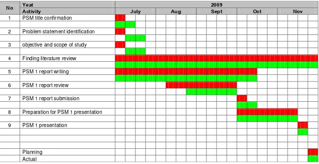
Table 1.2: PSM 1 Gantt chart 5
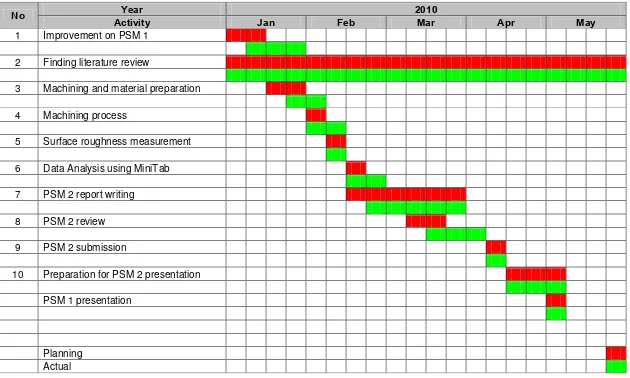
Table 1.3: PSM 2 Gantt chart 6
Table 2.1: General condition of cutting parameter for milling 17 Table 2.2: Recommended cutting speed for High Speed Steel cutting tool 18 Table 2.3: Table of mechanical properties for Mild steel 24 Table 2.4: Table of general information of machine 29 Table 2.5: Table of machine specification 30 Table 2.6: A 23 two-level, full factorial design table runs in standard order 35
Table 3.1: DOE matrix 40
Table 3.2: Cutting parameters for the experiment 40
Table 3.3: Data sheet for experiment 41
xii
LIST OF FIGURES
Figure 2.1: Element of end milling 8
Figure 2.2: A group of different end milling cutters 9
Figure 2.3: Down milling 10
Figure 2.4: Up milling 11
Figure 2.5: Parameters of milling 13
Figure 2.6: Recommended cutting speed for different materials 14 Figure 2.7: Shear length and shear angle in chip formation process 15 Figure 2.8: Roughness and waviness profiles 19
Figure 2.9: Surface roughness profile 22
Figure 2.10: HAAS CNC vertical milling machine 28
Figure 3.1: Process flow chart 37
Figure 3.2: Provided of raw material 38
Figure 3.3: End mill cutter 43
Figure 3.4: Surf Test SJ-301 47
Figure 3.5: Dimension of tester SJ-301 47
Figure 4.1: Normal plot of the residual 51 Figure 4.2: Normal plot of the standardized effects 52 Figure 4.3: Pareto chart of the standardized effects 54
Figure 4.4: Interaction plot for Ra 56
Figure 4.5: Main effect plot 59
Figure 5.1: Surface roughness produced at low feed rate, FR=175mm/min 62 Figure 5.2: Surface roughness produced at high feed rate, FR=450mm/min 63 Figure 5.3: Surface roughness produced at high cutting speed, CS=1300rpm 64 Figure 5.4: Surface roughness produced at low cutting speed, CS=750rpm 64
xiii
LIST OF ABBREVI ATIONS
AA - Arithmetic Average BUE - Built-up Edge CLA - Centre Line Average
1
CHAPTER 1
INTRODUCTION
1.1 Background Of The Study
Milling is a material removal process which can create a variety of features on a part by cutting away the unwanted material. The milling process is one of the fundamental forms of machining among several industrial machining processes. End-milling is the most common metal removal operation encountered. It is widely used in various fields of manufacturing industries including the aerospace and automotive sectors, where quality is an important factor in the production of slots and dies in both sectors.
2
However, factors such as tool geometry, tool wear, and chip formation, or the material properties of both tool and workpiece are uncontrolled (Hyunh & Fan, 1992).
Generally, one could use or refer the hands on data tables that are provided in machining data handbooks as a starting point to determine the cutting parameters. Other conventional method that can be used to determine the optimal machining condition is by using trial and error approach. However, it is very time consuming process to identify the optimum cutting condition for a particular operation. Nowadays, a Design of Experiment (DOE) has been used to select manufacturing process parameters that could result in a better quality product (Yang & Chen, 2001). The DOE is an effective approach to optimize the throughput in various manufacturing-related processes (Fidan et al., 1998).
This study is mainly about an experimental test to begin the characterization of surface quality of mild steel for the end-milling process. The study will discover the effects of machining parameters on the surface roughness of the mild steel using three different factors in the end-milling process. The three different parameters will result vary surface roughness. Hence, from the result obtain the optimum parameters can be identified. In order to analyze the data obtained, the DOE approach will be used.
1.2 Problem Statement
3
parameters which are cutting speed, feed rate, and depth of cut have been choosing with the aim to study and understand the effect on the surface roughness.
1.3 Objective
The purposes of this study are:
- To invetsigate the effect of the machining parameters on the surface roughness in the end milling process on mild steel
- To identify the optimum value of the machining parameters involved in producing a good surface finish
1.4 Scope Of Project
4
1.5 Organization Of The Report
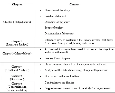
Generally, this report is divided into two parts which are Projek Sarjana Muda (PSM) I and PSM II. Overall this report contains of six main chapters. The five main chapters are divided into two parts which the first part contains three chapters that consists of introduction, literature review and methodology whereas the second part followed by the two more chapters; results and discussion and finally, conclusion and recommendation of the study.
Table 1.1: Organization of the Report
Chapter Content
- Literature review containing the theory involve that taken
from taken from journal, books, and articles
Chapter 3 (Methodology)
- Show the result obtain from the experiment conducted
- Analysis of the data obtain using Design of Experiment
Chapter 5
(Discussion) - Discussion on the result obtain
Chapter 6 (Conclusion and Recommendation)
- Conclusion on the finding
7
CHAPTER 2
LITERATURE REVIEW
The literature review is conducted in order to achieve the objectives of this research. It contains of the information of the end milling operation, machining parameters used, surface roughness and some overview of material used. All of this information is served as the guidelines for this study. It also used to support the result of the study.
2.1 Introduction
8
Figure 2.1: Element of End Milling (Moltrecht, 1981)
2.1.1 End Milling
9
Figure 2.2: A Group of Different End Milling Cutters (Moltrecht, 1981)
2.1.2 Methods of Milling
Basically, there are two methods in which a milling cutter can be fed into the workpiece. The two methods of milling can be known as down milling and up milling methods. Both methods can be applied in machining depend on the material of the workpiece.
2.1.2.1Down Milling
10
Figure 2.3: Down Milling (Youssef & El-Hofy, 2008)
The cutting forces in down milling are directed downward. The workpiece is pushed down and into the cutter. Hence, less clamping and machining power are required. The extra force places more stress on the machine slides and ball screws. Thus, this method of milling should not be attempted if machines do not have enough rigidity and are not provided with backlash eliminators. Under such circumstances, the cutter climbs up on the workpiece and the arbor and the spindle may be damage.
Advantages of down milling include the following:
Fixtures are simpler and less costly, as cutting forces acting on downward
Flat workpieces or plates that cannot be firmly heldcan be machined by down milling
Cutter with higher rake angles can be used, which decrease the power requirements
Tool blunting is less likely