UNIVERSITI TEKNIKAL MALAYSIA MELAKA
ERGONOMIC DESIGN OF COMPUTER NUMERICAL
CONTROL MILLING MACHINE USING QUALITY
FUNCTION DEPLOYMENT
This report submitted in accordance with requirement of the Universiti Teknikal Malaysia Melaka (UTeM) for the Bachelor of Manufacturing Engineering
(Manufacturing Management) (Hons.)
by
NUR SYAHEERA BINTI AHMAD
B050910087
900729-08-5234
UNIVERSITI TEKNIKAL MALAYSIA MELAKA
BORANG PENGESAHAN STATUS LAPORAN PROJEK SARJANA MUDA
TAJUK: Ergonomic Design of Computer Numerical Control Milling Machine Using Quality Function Deployment
SESI PENGAJIAN: 2012/13 Semester 2
Saya NUR SYAHEERA BINTI AHMAD
mengaku membenarkan Laporan PSM ini disimpan di Perpustakaan Universiti Teknikal Malaysia Melaka (UTeM) dengan syarat-syarat kegunaan seperti berikut:
1. Laporan PSM adalah hak milik Universiti Teknikal Malaysia Melaka dan penulis. 2. Perpustakaan Universiti Teknikal Malaysia Melaka dibenarkan membuat salinan
untuk tujuan pengajian sahaja dengan izin penulis.
3. Perpustakaan dibenarkan membuat salinan laporan PSM ini sebagai bahan pertukaran antara institusi pengajian tinggi.
(Mengandungi maklumat TERHAD yang telah ditentukan oleh organisasi/badan di mana penyelidikan dijalankan)
Alamat Tetap:
DECLARATION
I hereby, declared this report entitled “Ergonomic Design of Computer Numerical Control Milling Machine using Quality Function Deployment” is the results of my
own research except as cited in references.
Signature : ………
Author’s Name : NUR SYAHEERA BINTI AHMAD
APPROVAL
This report is submitted to the Faculty of Manufacturing Engineering of UTeM as a partial fulfillment of the requirements for the degree of Bachelor of Manufacturing Engineering (Manufacturing Management) (Hons.). The member of the supervisory is as follow:
i
ABSTRAK
ii
ABSTRACT
iii
DEDICATION
Specially dedicated to my beloved family, supervisor, lecturers and also friends for all their guidance and moral supports throughout my life.
iv
ACKNOWLEDGEMENT
First and foremost, I would like to express my gratitude to my supervisor, Dr Isa Bin Halim, lecturer of Manufacturing Engineering (Management), Universiti Teknikal Malaysia Melaka for providing me his valuable knowledge, as well as his own time to spend with me in overcoming the difficulties that has been faced during the whole process of the study. I would also like to thank my family for their encouragements and main supports for me to keep on going. Furthermore, I would also like to acknowledge all technical staff of Faculty of Manufacturing Engineering, who gave permission to use the equipment in completing my project. A many thanks as well to all of respondents who have volunteered in completing the survey for my project.
v
2.2.1 Quality Function Deployment (QFD) 11
2.2.2 Kano Model 14
2.3 Simulation of Working Posture 18
2.3.1 Working Posture 18
2.3.2 Computer-Aided Design 20
2.3.3 CATIA Software 22
vi
CHAPTER 3: METHODOLOGY 28
3.1 Determination of Customer Requirements and Ergonomic 28 Features of CNC Milling Machine
3.1.1 Questionnaire Development 28
3.1.2 Respondents 30
3.1.3 Survey Period 31
3.1.4 Survey Method 31
3.2 Redesign of CNC Milling Machine 33
3.2.1 Kano Model Analysis 33
3.2.2 Quality Function Deployment 36
3.2.3 Design Process – Sketching 39
3.2.4 Design Process – Drafting 43
3.3 Simulation of Working Posture 45
3.3.1 Manikin Development for Analysis 45
3.3.2 RULA Analysis 48
CHAPTER 4: RESULTS AND DISCUSSION 52
4.1 Results of Customer Requirements and Ergonomics 52 Features of CNC Milling Machine
4.1.1 Demographic of Respondents 52
4.1.2 Customer Requirements 58 4.1.3 Ergonomics Feature Requirements 62
4.2 Redesign the CNC Milling Machine 64
4.2.1 Build House of Quality (HoQ) 64
4.2.2 Selection of Conceptual Design 67
4.2.3 Final Design 71
4.3 RULA Analysis 74
vii CHAPTER 5: CONCLUSION AND SUGGESTION FOR 90
FUTURE WORK
5.1 Information from Respondents Related with Existing 90 CNC Milling Machine
5.2 Redesign of the CNC Milling Machine based on 90 Quality Function Deployment
5.3 Effectiveness of the Redesigned CNC Milling Machine 91
5.4 Suggestions for Future Work 91
REFERENCES 92
APPENDICES 95
A A Survey on Ergonomic Design of CNC Milling Machine Using Quality Function Deployment
viii
LIST OF TABLES
2.1 Summary of Journal Based on Determination of Customer Requirements and Ergonomics Features
10
2.2 Summary of Journals Related to QFD 17
2.3 Summarization of Journals Regarding with Simulation of Working Posture and RULA Analysis
27
3.1 Functional-Dysfunctional Table in Process of Traditional Kano Model
34
3.2 Table Used for Requirements from Machinist as well as Relative Importance
36
3.3 Machinist’s Requirements with Technical Specifications 37
4.1 Demographic of the Respondents (Age and Working Experience) 53 4.2 Number of Respondents and Type of Company 53 4.3 Application of the CNC Milling Machine and the Number of
Respondents
55
4.4 Number of Respondents Corresponding to Price Tag 56 4.5 Kano Model table of Customer Requirements 59
4.6 Values of CSs and DSs 60
ix
LIST OF FIGURES
1.1 Illustration of Report Outline 4
2.1 Matrix section in House of Quality 13
2.2 Customer’s Satisfaction in Kano Model 16
2.3 Working Posture Evaluation Method using OWAS 19 2.4 RULA Method in Evaluating Working Posture 20 2.5 Example of 3D Model of the Assembled Products and Manual
2.8 Body Posture Analysis using CATIA from Generated RULA Analysis 26
3.1 Process Flow of Developing the Questionnaire and Conducting Survey 32 3.2 Process Flows in Analyse using Traditional Kano Model 34
3.3 Relationship Curve of Kano Model 35
3.4 Complete Structure of HoQ after Inserting the Value of Relative Importance
38
3.5 Process Flow of the HoQ Development 39
3.6 Process Flow of the Design Process 40
3.7 Random Sketch for CNC Milling Machine Design 40 3.8 Sketch of the Machine on its Workstation 41 3.9 Random Sketch for Control Panel of CNC Milling Machine 41 3.10 Sketch of the Machine with other Design 42 3.11 Rough Idea of CNC Milling Machine Design 42 3.12 Design that has been Selected for Drafting 43
3.13 Draft of CNC Milling Machine Body 44
x 3.16 Basic Anthropometric for Malaysian Man 46 3.17 Structure of Manikin that has been Built to use for Human Analysis 47 3.18 Body Posture that is Adjusted using the Posture Editor 47
3.19 Close Up for the Posture Editor 48
3.20 Process Flow Chart for Developing the Manikin 48 3.21 Final Score that is Formed after Choosing Parameters 49
3.22 RULA Analysis by Colour Code 50
3.23 Flow for RULA Analysis Process 50
3.24 Overall Process Flow 51
4.1 Number of Respondents According to the Education Background 54 4.2 Number of Respondents and Frequency of using the CNC Milling
Machine
55
4.3 Number of Respondents Corresponding to the Machine Manufacturer 56 4.4 Number of Respondents Corresponding to the Level of Fatigue in the
Body Parts
58
4.5 Kano Model of Customer Satisfaction 61
4.6 Number of Respondents Corresponding to the Ergonomics Features Requirements
63
4.7 Results from the House of Quality for the CNC Milling Machine 68
4.8 Isometric View of CNC Milling Machine 72
4.9 Front View of CNC Milling Machine 72
4.10 Position when Changing the Tool Bit on the Tool Holder and Close-Up Position
76
4.11 Position when Changing the Tool Bit on the Tool Holder in CATIA 77 4.12 Result of RULA for the Right Side of Working Posture One 77 4.13 Result for Left Side of Working Posture One 78 4.14 Position of Controlling the Control Panel 79 4.15 Replication of Position for Control Panel in CATIA 80
4.16 Result for the Right Side 80
4.17 Position of Handling the Workpiece 81
4.18 Replication of Position for Handling Workpiece in CATIA 82
xi
4.20 Result for the Right Side 83
4.21 New Working Posture while Changing the Tool Bit 84
4.22 Result for the Left Side of the Body 84
4.23 Result for the Right Side of the Body 85 4.24 New Working Posture for Controlling Panel Position 86
4.25 Result for Right Side 86
4.26 New Working Posture while Handling the Workpiece 87
4.27 RULA Result for Left Side 88
xii
LIST OF ABBREVIATIONS, SYMBOLS AND
NOMENCLATURE
CAD - Computer Aided Design
CATIA - Computer Aided Three-Dimensional Interactive Application CNC - Computer Numerical Control
CR - Customer Requirement CS - Customer Satisfaction DS - Customer Dissatisfaction DOF - Degree of Freedom
kg - Kilogramme
mm - Millimetre
HB - Human Builder
HOQ - House Of Quality
HME - Human Measurement Editor
OWAS - Ovako Working Posture Analysis System PDM - Product Data Management
QFD - Quality Function Deployment REBA - Rapid Entire Body Assessments RULA - Rapid Upper Limb Assessment SKM - Sijil Kemahiran Mara
SPM - Sijil Pelajaran Malaysia USA - United State of America
UTEM - Universiti Teknikal Malaysia Melaka VOC - Voice Of Customer
1 This chapter provides the information on background of study, problem statements, objectives of study, scope and limitation of study and report outlines.
1.1 Background of Study
CNC milling machine is one of machines that are usually used in the manufacturing industry and educational institutions to produce simple and complex parts from various materials. The CNC milling machine also known as machine tool that is classified into two basic forms horizontal and vertical orientations. Its invention has created a large impact on the manufacturing industry due to the fact that the machine itself can cut the parts over and over again in an absolute accuracy. The machine works by inputting the programming that already been programmed by the machinists and it will cut according to the set of the programme. The advantages of CNC milling machine can be associated with fast mass production and high precision and accuracy.
Although the CNC milling machine helps the machinist in terms of speed up the work, and precision and accuracy, the machinist may be experience ergonomic problems such as muscle fatigue due to poor working posture while operating the machine. The machinist performs the machining process in poor working posture when he or she has to twist the trunk to grasp the workpiece on the worktable located at side or rear position (Macias et al., 2009). In addition to that, the machinist might
2 also experience visual discomfort due to poor position of the visual display unit attached to the machine (Ali Khan, 2012).
Nowadays, there are several methods available to improve the ergonomics-related problems in the CNC milling machine. One of the popular methods is using the Quality Function Deployment (Akao, 1993). The Quality Function Deployment or known as QFD is a concept that provides translation of customer requirements into technical requirements on each stage of the product development and production. The QFD was originally proposed by collecting and also analyzing the voice of customer (VOC) in order to develop the products with a higher quality so that it will meet the customer’s needs (Chan and Wu, 2002). In this study, the House of Quality in QFD will be developed based on the machinists’ requirements that are needed technically and ergonomically.
Realizing the needs to design the CNC milling machine ergonomically, this study is performed to improve the working posture of the machinist while operating the machine. To do that, the QFD was deployed in redesign the CNC milling machine.
1.2 Problem Statements
Based on literature review, the existing design of CNC milling machine has a limitation as it leads to ergonomics risks that can be summarized as follow:
1) The machinists experience muscle fatigue due to repetitive movement and awkward working posture. They tend to experience muscle fatigue, especially in the upper limb such as shoulder muscle (Brookham et al, 2010).
3 As the consequences to these ergonomic risks, the working condition will affect the productivity, efficiency and concurrently reduce the competitiveness of the industry. This is can be achieved by applying good ergonomic design so that productivity and efficiency can be improved.
1.3 Objectives of Study
The aim of this study is focusing on the ergonomic design associated with working posture when operating CNC milling machine. Consequently, the objectives of this study are:
(i) To determine customer requirements and the ergonomics features needed by the machinist with regard to the CNC milling machine design.
(ii) To redesign a CNC milling machine by considering the requirements of the machinist.
(iii) To simulate the working posture of the machinist while operating the redesigned CNC milling machine.
1.4 Scope and Limitation of Study
4 1.5 Report Outline
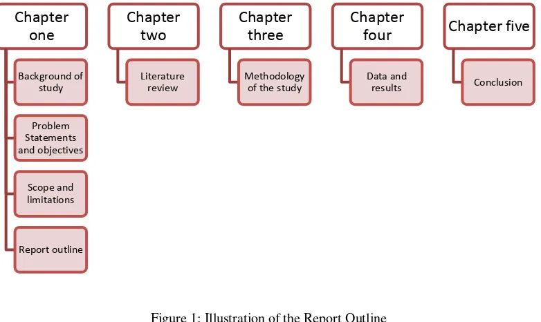
In chapter one, it provides an introduction of the study, the problem statements of the study, objectives, scope and limitation of the study and also the report outlines. The main objectives of the project are to determine the technical specifications and ergonomics requirements needed by the machinists for the machine, redesign the machine as well as simulate the working posture of the machinist while operating the machine itself. The scope and limitations of the project explain the range of the project that will be done and the limits of the project itself.
In chapter two, the literature review is provided in order to support the discussion and the methodology of study. The literature review was performed by online search through journals and other reliable resources. Chapter three discusses the method applied to redesign the CNC milling machine.
Chapter four presents the data and results obtained through the questionnaire survey. Last but not least, chapter five concludes the findings of study and it provides recommendations for future improvement. Figure 1 illustrates the report outline.
5 This chapter provides the literature review on technical specification and ergonomic requirements regarding CNC milling machine; and the effects of CNC milling machine design on working posture. The information and knowledge are obtained through hardbound and online journals, relevant articles and reference texts.
2.1 Determination of Customer Requirements and Ergonomics
Requirements
2.1.1 CNC Milling Machine
The computer numerical control (CNC) milling machine has been developed over 200 years ago. The CNC milling machine is a machine that is used to machine solid materials into specified shapes and sizes according to technical specification. It can produce various ranges of products from simple to complex parts. Most of the CNC milling machines are run using the computer controllers. The machine is able to translate programs that may consist of specific numbers and letters in order to move the spindle to various locations and depths (Banu, 2012). The CNC milling machine can be classified into two types; vertical and horizontal orientations. The vertical milling machine has the ability to perform the movement of the spindle in vertical along the axis of Z. Due to extra degree of freedom, its performance would be better than the conventional ones. It can also improve the milling precision without even
6 moving an impacting speed of the cutting tool machine; and at the same time provides a cost-efficient alternative to most of the flat surface workpiece. For the horizontal milling machine, it has a variety of cutters where the cutter can be changed easily. It generally performs a face cutting which is directly from the spindle and allows side, face and form machining in only one operation. The horizontal milling machine also contains a drive motor and gearing with a fixed position spindle. Concurrently, it allows the workpiece that is mounted to be rotated in a horizontal position, which allows the turning to be asymmetric and eccentric.
In designing a CNC milling machine, it should be designed ergonomically on which the machinists can perform milling operations in a safe working condition. In the next section, it describes on the ergonomics approach relating to CNC milling machine design.
2.1.2 Ergonomics Approach
In developing a product, designers should consider ergonomics in their product designs. The primary aim of ergonomics is to fit people, tools and environment. It considers the people’s capabilities and also limitations in order to ensure tasks, equipment, information and environment works efficiently. Ergonomic is defined as a study of interactions between people and machines as well as factors that affect the interactions (Bridger, 2003). It is also referred to as a study of human characteristics for an appropriate design of both living and working environment (Kroemer et al., 2000). Another advantage of ergonomics is that making the workplace is safe to the workers so that efficiency and human well-being can be increased.
7 safety, satisfactions, productivity and high work quality (Shahnavaz, 1988). Improvement in the workplace can be carried out through reactive or proactive approaches (Ali Khan, 2012). By applying ergonomics in the designs or workplaces, the levels of risk for the musculoskeletal disorders can be reduced (Macias et al., 2009).
A proactive approach in ergonomics is an approach of whereby it is to prevent any work-related musculoskeletal disorders (MSDs). The technique of this approach is by recognising risk factors in planning stage of the workplace before proceed to anticipate and reduce the risk factors. In other words, the proactive approach is applied in the design stage of workstation to avoid any potential risk for MSDs. Through proactive approach, discomfort survey is commonly used as a tool to identify any perception pain at various body locations. The advantage of this tool is that it can help to identify jobs that can contribute to potential injuries (Resnick, 1996). Furthermore, proactive approach provides a better view of the problems and actions in order to minimize the risk of MSDs at design stage of the work process or the product (Feletto et al., 2000). Example of proactive approach is design of bus driver seat where the seat is too small that has poor back support and neck posture. By using this approach, the seat has been redesigned by making the seat larger where it is more comfortable and the back support has been improved. As for reactive approach, it is an approach where it used to take action in situation that needs to be fixed. In this case, this approach is being done by deal with the current problems that are already present by using passive techniques. It is also known as an approach that used to oppose the incoming changes and tries to slow it down, stop or reverse the action (Jean et al., 2009).
8 towards risk condition (Michael, 2001). In terms of engineering control method, it is the most preferred method in order to control the ergonomics risk factors due to the fact that it is more permanent and effective. In other words, it is also referred to as redesign, modify or replace in terms of workplace, machines, hand tools and equipment. When the design of the workplace or machines is made, it will reduce the magnitude of the risk factors. At the same time, the likelihood of the injury will be diminished as well (Michael, 2001). For the next section, common method that is used to determine the requirements that the customers wants and needs by making surveys using questionnaires.
2.1.3 Questionnaire Survey