i
SUPERVISOR DECLARATION
“I hereby declare that I have read this thesis and in my opinion this report is sufficient in terms of scope and quality for the award of the degree of
Bachelor of Mechanical Engineering (Automotive).”
ii
SIMULATION OF AIR FLOW AROUND VEHICLE FRONT WINDSCREEN
MUHAMMAD YAZID BIN HASNAN
This report is presented in Partial fulfilment of the requirements for the
Bachelor of Mechanical Engineering (Automotive)
Faculty of Mechanical Engineering Universiti Teknikal Malaysia Melaka
iii
DECLARATION
“I hereby declare that the works in this report is my own except for summaries and quotations which have been duly acknowledged.”
iv
To my beloved parents, Mr. Hasnan Bin Mohd Zin and Mrs. Kamariah Bt Ngah... My family...
My Supervisor, Mr. Fudhail Bin Abdul Munir... My friends...
v
ACKNOWLEDGEMENT
I would like to express my gratitude to all those who gave me the possibility to complete this project. I want to thank to Allah S.W.T for giving me good health to do the necessary research work. In addition, I would like to thank to my fellow friends who always encouraged me with this project.
I am deeply indebted to my supervisor, Mr. Fudhail bin Abdul Munir from Faculty of Mechanical Engineering whose help, stimulating suggestions and encouragement helped me in all the time of the research and writing of this Final Year Project.
vi
ABSTRACT
vii
ABSTRAK
viii
CONTENTS
CHAPTER TITLE PAGE
DECLARATION
DEDICATION
ACKOWLEDGEMENT
ABSTRACT
ABSTRAK
CONTENTS
LIST O FIGURE
LIST OF SYMBOL
CHAPTER 1 INTRODUCTION 1
1.1 Overview 1
1.2 Problem Statement 2
1.3 Objective 2
1.4 Scope 2
ix
CHAPTER 2 LITERATURE REVIEW 4
2.1 Overview 4
2.2 Vehicle Windscreen 4
2.3 Computational Fluid Dynamics (CFD) 6 2.3.1 Turbulence Model 7
CHAPTER 4 RESULT AND DISCUSSION 32
4.1 Overview 32
4.2 Flow Streamline and Pressure Distribution on Vehicle Models 32 4.3 Pressure and Velocity Variation on
x
4.4 Variation of Pressure Coefficient in Vehicle
Models 40
CHAPTER 5 CONCLUSION AND RECOMMENDATION 43
5.1 Conclusion 43
5.2 Recommendation 44
REFERENCES 45
xi 4 Turbulnet flow around a car computef from Navier- Stokes
equations with slip boundary condition 10 5 Illustrate ANSYS CFX procedure 11 6 Illustrate the laminar separation on a car body 13 7 Illustrate the boundary layer thickness of a car 14 8 Illustrate the turbulent and laminar boundary layer 15 9 Illustrate turbulence and laminar flow through pipe 17
10 Flow chart of methodology 20
xii
21 Flow streamline on car model (3D). (a) Perodua Kenari,
(b) Perodua Myvi and (c) Proton Saga BLM 34 22 Pressure distribution on car model. (a) Perodua Kenari,
(b) Perodua Myvi and (c) Proton Saga BLM 36 23 Pressure variation against distance of vehicle models. (a) Perodua
Kenari, (b) Perodua Myvi and (c) Proton Saga BLM 38 24 Velocity variation against distance of vehicle models.(a) Perodua
Kenari, (b) Perodua Myvi and (c) Proton Saga BLM 40 25 Cp variation against distance of the vehicle models. (a) Perodua
xiii
LIST OF SYMBOL
ρ
Density of air at 300K
V Free stream velocity
µ
Dynamics fluid viscosityRe Reynolds number L Characteristic length Cp Pressure coefficient P Pressure at the car
1
CHAPTER 1
INTRODUCTION
1.1OVERVIEW
This research was conducted to study the flow around a vehicle front windscreen. Modern windscreen is made of laminated safety glass, a type of treated glass, which consists of two curved sheets of glass with a layer laminated between them for safety [1].
Windscreen plays an important role in the overall design of a vehicle. It is used to protect the vehicle’s occupants from external variables such as wind, extreme temperature and flying object, as well as providing an aerodynamically formed window.
In this study, Computational Fluid Dynamics (CFD) is used to determine the flow pattern around a vehicle front windscreen. CFD software is used to calculate the pressure distribution, drag and lift coefficient in order to define the flow pattern around a vehicle front windscreen.
2
Comparison between three national car model which are Proton Saga BLM, Perodua Myvi and Perodua Kenari to investigate the effect of the flow pattern. All car model are chosen based on the average car been used by Malaysian. The result of this study hopefully can be used as a reference and guideline by other researcher.
1.2PROBLEM STATEMENT
At average speed (90km/h) and above, as driving speed increased, aerodynamic noise on ground vehicle were becoming relatively effect the comfort of the occupants especially at the area of front windscreen and side mirrors. It is vital for the researcher and engineer to study these phenomena in order to rectify the problem for the future models.
1.3OBJECTIVE
The objectives of this study are:
1. To study flow around a vehicle front windscreen.
2. To obtain the flow pattern around a vehicle front windscreen.
1.4SCOPE
The scopes of this proposed project are:
1. Simulate flows for different s national car’s model which is Proton
Saga BLM, Perodua Myvi and Perodua Kenari.
3
1.5EXPECTED RESULT
4
CHAPTER 2
LITERATURE REVIEW
2.1 OVERVIEW
This chapter will define and discuss the information related to the background knowledge of vehicle windscreen, the aerodynamic theory and the used of Computational Fluid Dynamics (CFD) in determining the flow around front windscreen of a vehicle. Reviews on previous studies concerning the flow on frontal area of vehicle are included as well.
2.2 VEHICLE WINDSCREEN
5
part of any car and the unfortunate thing is that they are prone to damage. The windscreen is usually made of glass which is a fragile material by nature, this means when driving extra care should be taken to ensure that the windscreen is in perfect condition each time when turn on the engine to prevent further problems.
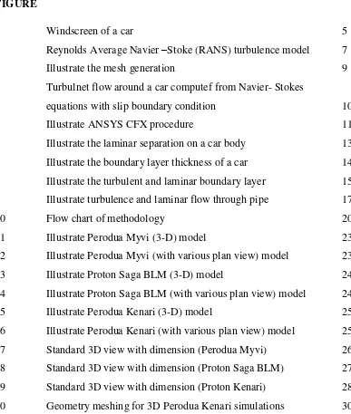
Windscreen mainly use to protect the vehicle's occupants from wind, temperature extremes, and flying debris such as dust and rocks, as well as providing an aerodynamically formed window towards the front[1]. Modern windscreens are well made and designed to be dual layered, it also aids in the rigidity of the structure of the car. As with many modern products it goes through intense quality checking to reduce the chance of it being easily damaged. The windscreen though, takes a lot of wear and tear in part due to the wiper blades.
Figure 1: Windscreen of a car
6
A stone chip is the most common form of damage when it comes to windscreens. There are many road works taking place across the country and this normally means gravel, grit and other debris on the road. When driving around areas with poor road surfaces of which are covered in loose surface materials, take extra care and drive slowly so the stones are less likely to get flicked up on to the windscreen and potentially chipping or cracking it.
Chips in a windscreen can start off as a minor problem but it can quickly turn into a bigger problem as the chip cracks the glass surface. This is why it is very important to get the chip repaired as soon as you notice it. The main reason is cost as getting a chip repaired is relatively cheap and some companies will do it for free if you have the right insurance cover. Buying a new windscreen can cost lots of money depending on the model of the car. It is also more environmentally friendly to get a chip fixed as your original windscreen will not have to be disposed of.
2.3 COMPUTATIONAL FLUID DYNAMICS (CFD)
Computational Fluid Dynamics (CFD) is one of the branches of fluid mechanics that uses numerical methods and algorithms to solve and analyze problem that involve fluid flows [2]. CFD predicts the fluid problem by describing the fluid flow case mathematics equation and solving it. The mathematical technique includes finite deference method, finite element methods and filter –scheme methods.
7
CFD can be applied in many fields of researches; one of the fields that gain the most advantages from the development of CFD methods was the aerodynamics field. By using CFD, the details about the flow field such as shear stress, velocity and pressure profile and flow streamlines can be obtained [3].
2.3.1 Turbulence Model
Turbulence is very complex and details of turbulence motion are too small scale in diameter. The CFD simulations of turbulence flow are much more difficult than laminar flow. Turbulence flow always unsteadies and three dimensional – random, swirling, vertical structure called turbulence eddies of all orientations arise in turbulence [3].
Complexity of different turbulence models may vary depends on the details that want to be observed and investigate by carrying out such numerical simulations. Complexity is due to the nature of Navier-Stoke equation (N-S equation). N-S equation is inherently nonlinear, time-dependent and three-dimensional [13].
8
Turbulence could be thought of as instability of laminar flow that occurs at high Reynold numbers (Re). Instability of laminar flow forms an interaction between non-linear inertial terms and viscous term in N-S equation. These interactions are rotational and fully three-dimensional. That is why no satisfactory two-dimensional approximations of turbulence flow are available.
Even though, certain properties could be learned about turbulence using statistical methods. These introduce certain correlation functions among flow variables. However it is impossible to determine these correlations in advance.
There are some characteristic features of turbulence flow such as irregularity, random and chaotic. Turbulence flow occurs at high Reynold number, for example, the transition to turbulence flow in pipes occurs at Re= 2300 and in boundary layer at Re=100000. In addition, diffusivity also some of the characteristic of turbulence flow. This means that the spreading rate of boundary layers increase as the flow becomes turbulent.
2.3.2 Mesh Generation.
Mesh generation is the first step in CFD solution, which consists of defining the cells on which flow variables such as velocity and pressure are calculated throughout the process [3]. Meshing is an integral part of the CAE analysis process. The mesh influences the accuracy, convergence, and speed of the solution [10]. The time to create a mesh model is often a significant of the time it takes to get the results from CAE solution. The better and more automated the meshing tools, the better the outcome solution.
9
example triangles that are almost equilateral) to get accurate discretizations and well conditioned linear systems [11].
Figure 3: Illustrate the mesh generation [35]
An unstructured mesh is usually applied to the complex geometries. However, there are some advantages unstructured mesh compare to structured mesh, it converges more rapidly and often are more accurately by utilizing the index feature of structured mesh.
2.3.3 Boundary Condition
10
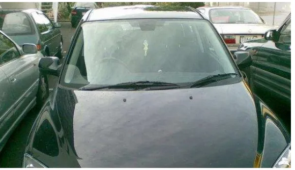
There are several types of boundary condition which is wall boundary condition, inflow/outflow boundary condition, miscellaneous boundary condition and internal boundary condition [3]. Wall boundary condition is the simplest boundary condition, since the fluid cannot pass through a wall and the non-slip condition. Appropriate boundary conditions are required in order to obtain an accurate CFD solution.
Figure 4: Turbulent flow around a car computed from Navier-Stokes equations with slip boundary condition [14]
Different boundary conditions may cause quite different simulation results. Improper sets of boundary conditions may introduce nonphysical influences on the simulation system, while a proper set of boundary conditions can avoid that. So arranging the boundary conditions for different problems becomes very important. While at the same time, different variables in the environment may have different boundary conditions according to certain physical problems.
11
2.3.4 Structure of a CFD
ANSYS CFX software has three basic components, which are pre- processor, solver and post-processor. The pre-processor consist of three main components: geometry, meshing and pre-CFX. Pre-processor has various numbers of function that allows user to predefine the domain fluid, known as computational domain and build the geometry of the zone (surface) considered, creating a mesh system and tuning the mesh to improve the computational result and quality. User also may specify the properties of the domain fluid and other material that been used at this stage.
The solver in ANSYS CFX will carry the major computations and providing the numerical solutions. It consists of two components that will define the equation and come out with the solution. The output of the solver is a set of flow variables at the mesh nodes.
The post-processor will then construct a picture of the simulated flow problem by displaying the geometry of the problem, the computational domain and the mesh system [34].
Figure 5: Illustrate ANSYS CFX procedure [34] Pre-processor
Geometry
Meshing
Pre-CFX
![Figure 2: Reynolds Average Navier- Stoke (RANS) turbulence model [15]](https://thumb-ap.123doks.com/thumbv2/123dok/588849.70205/20.595.189.448.497.673/figure-reynolds-average-navier-stoke-rans-turbulence-model.webp)
![Figure 3: Illustrate the mesh generation [35]](https://thumb-ap.123doks.com/thumbv2/123dok/588849.70205/22.595.192.458.138.330/figure-illustrate-the-mesh-generation.webp)
![Figure 5: Illustrate ANSYS CFX procedure [34]](https://thumb-ap.123doks.com/thumbv2/123dok/588849.70205/24.595.114.532.470.662/figure-illustrate-ansys-cfx-procedure.webp)
