Internabnal Seminar on the Application of Science &
M*rT-i{t;31
IDEVELOPMENT
OF
IMAGE
RECOGNITION
ALGORITHM
FOR
IINDERWATER
VEIII
CLE APPLICATION
SSyed Mohannd Shazari
",;,:r;lf*I
?x}*l,
y;m.;il#^ttr;1Ta
Ashikin Binti Ari3, Anuar
Departnrcnt of Mechatronics, FKE, UTeM
1
[email protected],2 shahrieet@ute
,j;:l;f;@utem.edu-mv,
aThis project focuses on development of algorithm for.image recognition of images from.vision
iyri"ii
for
underwater vehicle' application-s. The main objective-of this project isto
develop aigorithm from vision system seniorfor Deep Submergence Vehicle (DSV) applications whichtr^'". frlgt
perfornnncJautomated detection and mo-nitoring 9rag$.on. anchored ship at. itsp".t7ao"i
ai
wellu,
rnouing ship.It
is also expected to reco[nize_biological underwater objectio
support on deck uuto .ro"nitoring system_Ttie develo.ped.algorithm will be used to recognize. relevant underwaterobi";i;aii"irE
ttiing.tt
is paper wiil d isc-uss the exp_erinrental setup as we llas the prior algorith m
irt
i"t
*itt
b"e use? for this^research. The approach that h ad been us ed to imitate the underwater worldwill
be presented as well as related issues on underwater visioni"if,r"fog,.
ffris
paper also discgsses the expected resultof
this
research and potential application of the developed algorithm.Keywords.. Vision systerq mu lti sensor systenr, DSV, underwater technologies.
1.
INTRODUCTION
This
project
isa
continuationof
a
previous project on design and developmentof
muhi
input sensor algorithm for Autonomous Underwater Vehicle
(AUV)
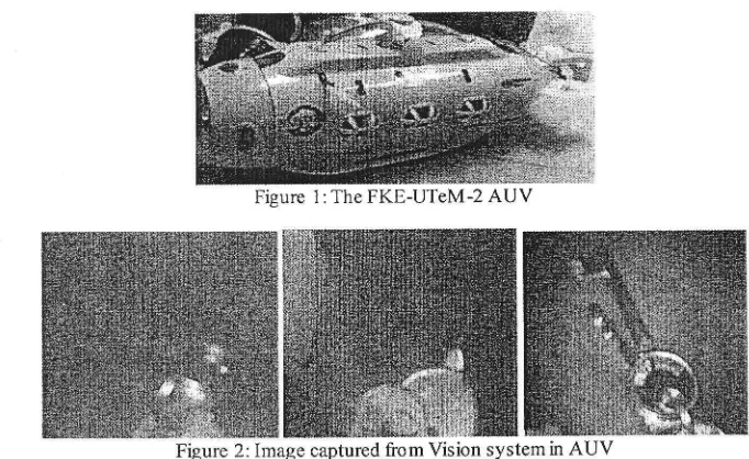
as shown in Figurel-
Themain
objectiveof
thisproject is
to
develop algorithmfrom vision
system sensorfor
AUV
applications
which
havehigh
performance automated detection andmonitoring
underwaterotject
orliving
thing.the
monitoring and detectionwill
be based onmuhiple
inputs receivedfrom an active vision sensors system and applied in the Deep Submergence Vehcile (DSV).
As
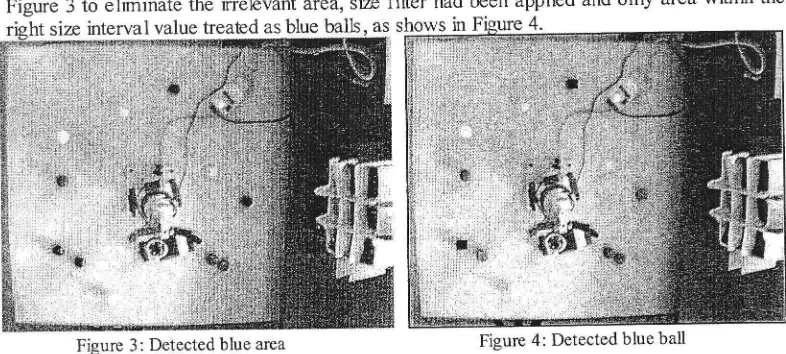
we investigate in the previous project, the imagesfrom
underwater are rrcry blurry anddifficult
to
recognizeby the vision
Jystem,as
shownin
Figure2.
The
experimentfor
thisproject
will
be done in three different conditionsof
water which are in the clear water, mix-upwaier
with
detergent aswell with
the
sludgewater as different
environmentmight
yielddifferent resuh
for
determiningthe
appropriate distancefor producing different quality
of
underwater images[1]. New
algorithmwill
be
introduced basedon dynamic
sizefifter
toenhance the image recognition capability of the vision system which could cater the challenges
imposed
by
undErwateienvironment.New
setof
vision sensor had been acquiredto
improve the resuhing input.Figure 1:The FKE-UTeM-2 AUV
Figure 2: Image captured from Vision system in AUV
The maior obstacle faced
by
underwater vision system isthe
extreme lossof
colour andcontrast when submerged
to
any significant depth whereby the imagequalty
produced is low.Therefore, as to obtain clearer images, several investigations
will
be done in order to know theappropriate distance required between the images with the caffPra.
The application
of
this vision system can be widen so that the usageof
the system is notonly limited
for
exploringthe
turderwater environment,but
alsocan be
usedin
education, research and rescue. However, in order to build this system,it
might costa
lot as it design andability
is quite complex and expensive. Therefore, this project had been proposed asto
designmore simple design of vision system for DSV with a lower costwith better performance.
The method that
will
be proposed to improve the image processing technic could coupwith
the
lacksof
qualityof
the underwater image. The similar algorithm had been used before towork on
environmentwith
luminanceof
20 lux.
However
the
challengeof
processingunderwater image would prove more
difficult
as the properties oflight
underwater are different from above water.Basically,
the
colour perceptionof
an object is depends on physical and components suchas spectral composition
of
light, spectral reflectance of the object, transmission ofthe light
inthe
medium, andthe visual
systemof
the
observer. Basically,the
processesof
underwatercolour modification involve
attenuationby
distance, absorptionfrom the object,
diffusionreflection from the object and attenuation by distance.
This project expected to produce working algorithm
which
is capable to recognize image inunderwater.
The
resuhis
expectedto
havefirrctional
andoptimum
performanceof
visionsensor ranging system arrangement and integrated and interfaced between the
DSV
and both(?2-Interndkrnal Seminar on the Applic?tion of Sciene &
M*rT^iif
33li
sensors system.
Ttn
display panel on the VisualBasic's
softwarc would show the monitoringand detecting by using the algorithm.
2.
METHODOI-OGY OF RESEARCH
The
algorithm
will
be testedby
assigningthe vision
systemto
recognize colouredball
underwater after
being testedto
ietect-the-same
object abovewater' Thls
approach wasdesigned to
simplify
the calibration of the system for the algorithm'The project setup is divided into
two
parts, hardware and software development' Hardwaredevelopment
major
phases includepreliminary
studyof
vision
sensorand
communication devicesfor
underwater application. Vision.yri"*
then designed and develops alongwith
itsvirtual control panel before it
will
ready to be integrated with theDSV
firmware arrangement tocomplete a task.
The software development major phases include preliminary study
of
image recognitionfor DSV,
design and developmentof
aigorithmfor
real time simulation, data input, coordinate processingan[ storinj
in.,ug"*"tt
o,iwhich
capturedby
DSV
using Windows
Softwareprog.urnr,'irg
lVlsuafiasic FUtfor*).
It will
also include designing a Graphical User interfaceICUU fot
its virtual control panel data input, data storage and processing'The whole system
will
then be tested ttnough a series of test-run and debuging algorithms'The
resultof
thetest
will
be usedto
improve data input and output processing and makingnecessary furalization on the algorithm and the integrated system'
3.
RECOGNITION
OFCOLOURED OBJECT
There are many ways
to
implementobject
classificationalgorithms'
In
the
previotsresearchers they are basei on colour
histogramf 4 ],
[
5],
motion detection[
6]
and templatematching
[
7],
but
using colourto
classify the objects is more^practical compare motion or template"mat"tirg. fft"-reason
is thereis
non""d
for other information from
other typeof
sensory pressrre or sonar, or to train the template for matching process'
To
determine
the
colours
in the
image
sequence,hue
saturation
value
has
been compensated the weakness of saturation value-[ 5].
This is because by using saturation value' the different colours with the same range of the iaturation are diffrcult to determine. Dependingon this situation, two components are needed to determine the colours.
For detecting cerfain colour, the saturated and hue value need to be used as every colour has
a different hue and saturated value.
After
the image of the front side of the cupboard has taken,the area
with
saturation valuewithin
the particular colour saturation valuewill
be selected byselecting
the pixels from the input
image whose saturation values,s
fulfil
the
followingcondition:
MinSaturation
<s
<MaxSaturation
(1)The value of the MinSaturation and MaxSaturation were selected so that all
or
most of the surface of everyb"ll*ith;;;i.*lar
colour i.e. blue covered'All
pointsof
an imagefulfilling
the condition are returnedas one region'Afterwards, this region
will
pass another filtering process so.that only the area-with""l-13jt
hue value
"o.r".ponding1"
tfr"'p"nltrlar
colour
*[nin
the regionwill
be treated as possiblesurface of the balls. Small areas or Iarge areas which are irrelevint to the balls in the region
will
be fihered out so that onty tt,eur"u
'iith
a reasonable sizewill
be detected andtreabd
as theballs with that particular colour.
Next, the detected coloured area transformed to rectangle shape depending 9n
jl"
smallestenclosing rectangle
ur"uiJfo*"a
by finding the centre poini of the each rectangle' These pointswill
be tieated as the centre point of the balls in the next process'4.
SIZEFILTER
For this operation, threshold operator is used to select connected region buih by connection region operator which have size
*ithi,
un intervalthatfulfilling
it minimum andmaximum sizecondition.
All
connectedregion
in the
imagethat
fulfilling
the
conditionare
returned aspossible object
of
irt"r"rt.
fn"
possibleuuhr] fo,
the sizemist
be choose properly sothat
itfodd
fifter outall
or at least most of its possfole noise'The fiher has two stages, namely as inner radius stage and box size stage' The inner radius stage
will
determines tf,"Tu.g"st inner circle radius of a-selected region'i'e''
the circle with thelargest area
of
all circles
trrutrrt into the
region.The
serie.s.9f
.yl'"
will
be
compared tothreshold,s size and eliminate those regionr
*ii"t
are notwithin
the range. The areafor
this
selected region then
*iiib;
transformed'to box shape for next shge of size frher'The box size stage
will fiher
out the boxes resuhed from the previous stage that are outsidethe previously calcuhled threshold value, a.
ih.
;;i..
will
be sei by calculating the averageof
the boxes' sizes. The
averap
size valuewill
be
coupledwith
suitable rangefor
each object whichwill
be classified in a form shown in Equation 3'AverageSize
-
RangeValue < a <AverageSize + RangeValue (3)5.
PRELIMINARY RESI]LTS
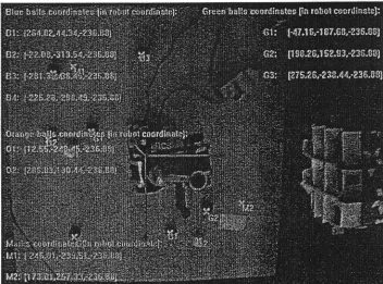
This experiment done
by
image taken from the camera placed on top of working space' Theimage
taken
includesblue, oranie
and greenballs
image.After
applyilB colour filter,
bluecolour
filter
for
example,all
areawith
same hue andsituration
vaiue detected' as shows inIntenational Seminar on the Application of Science & Mdhcnatics 201 I ISASM 2OI 1
Figure 3
to
eliminate the irrelevant area, sizefilter
had been applied andonly
area within the 4.The algorithm had also tested with bad light condition which was 12 lux, after the value
of
the
threshold had been adjustedspecifically
for
the image light condition; the
algorithms successfully detectall objeits
as shownin
Figure 5. The resufts also show the differences in success ratesfor
different colour. The algorithms work bestfor
orange colour but seem mostaffected by the light condition when detecting blue colour.
Figure 3: Detected blue area Figure 4: Detected blue ball
Figure 6: The output of algorithm with specific threshold value for bad lighting scenario
6.
CONCLUSION
This project focuses and objectives had been discussed. The developed algorithm
will
beused
to
recognize relevant underwater objector
living
thing. This
paperwill
discuss theexperimental setup as
well
as theprior
algorithmwhich
will
be
usedfor this
research. This paper also discusses the expected resuh of this research and its potential application.The expected resuft
of this
projectwill
be further proposed to the underwater applicationindustry.
The
intensionis to
promote underwater technolory based industrial application by making it more affordable.in
addition, through this project, staff competency and expertisewill
be develop especially
on
the advance sensor and controlalgorithm
aswell
asfirmware
andhardware practical implementation.
Acknowledgement
The authors
gratefully
acknowledgethe
financial supportfrom
UniversitiTeknikal
Malaysia Melaka(UTeM)
from their researches in underwater technology through various grant provided to the research group.International Seminar on the Applicdion of Science & Mathqnatics 201 I
ISASX\,I 201 I
Refercnces
tll
Butcher,J.
C.
(2003). Numerical Methodsfor
Odinary Dfferential fuuatians,New
Zealand: John Wiley
&
Sons.t2)
Hasling,D.
W.;
Clancey,W. J.;
and Rennels, G.R.
(1983). Strategic Explanations inConsuftation. The htternational Joumal of Man-Machine Sudies
20(l):
3-19.t3l
Kohfeld, J. J. &, Thompson, G.T.
(1967). Multi-step Methodswittr Modified
Predictorsand Correctors- J. Assoc. Comput. Mach.
,14:
155-166.t4l
Avi
Kah
&
Kosaka,A.
(1996)."Muhi
sensors Fusionfor
SensoryIntelligence
inRobotics.",. Proceedings
of
Workshop on Fotmdatbns of Information/DecisbnFwion:
Applbations
to Ettgineering Problems. Washington DC.t5l
Trevor,
T.
(2003). CollaborativeMap Building by
Autonomous Robots using VisualLandmarks. Facuhy
of
Information Technolory. QueenslandUniversity of
Technolory,Australia.
16l
Syed Mohamad Shazali,S.
A.,
Marlnn,
S.,
&
Azni,
S.
(2008).The
Fuzzy Logic Approach for Modelling Object Physical Features and Holes Occupancies. Proceedings of tutCon2008 (pp. 933-938). Kuching: MalaysiaI7l
S.M.
Shazali S.A. Hamid
M.
S. (2007). Analysis of Kinematics on Katana 6M Robot.Proceedings of the
hternatbnal
Confermce on Engineering and ICT, Melakq, Malaysia.