‘I hereby declare that I have read this dissertation and found its content and form
to meet acceptable presentation standards of scholarly work for the award of Bachelor of Mechanical Engineering (Thermal-Fluid)’
Signature : ………
Supervisor : MR. MOHAMMAD FIRDAUS BIN SUKRI
THE HOLDER OF THERMOELECTRIC POWER GENERATOR (TEG) BASED HI-Z THERMOELECTRIC MODULES
MUHAMMAD MUSLIM BIN MUSTAFFA
A report submitted in partial fulfillment of the Requirement for the award of the degree of Bachelor of Mechanical Engineering (Thermal-Fluid)
Faculty of Mechanical Engineering Universiti Teknikal Malaysia Melaka
ii
I declare that this thesis entitled “The holder of thermoelectric power generator (TEG) based Hi-Z thermoelectric modules” is the result of my own research except as cited in
the references.
Signature : ...
Author : MUHAMMAD MUSLIM BIN MUSTAFFA
iii
DEDICATION
iv
ACKNOWLEDGEMENT
First of all, I would like to show my appreciation to gratefulness, ALLAH SWT in order to complete my undergraduate project. I also would like to express my gratitude and appreciation to all who gave me support to complete this thesis especially to my supervisor Mr. Mohamad Firdaus bin Sukri, for his valuable suggestions, commitment, support, advised, time shared, encouragement and guidance.
A lot of appreciation and thankful to Mr. Mad Nasir bin Ngadiman for his supervision during working on this project. I would like to thankful to my parent for their endless support and encourage to all of my work.
v
ABSTRACT
vi
ABSTRAK
vii
CONTENTS
CHAPTER TITLE PAGE NO.
DECLARATION ii
DEDICATION iii
ACKNOWLEDGEMENT iv
ABSTRACT v
ABSTRAK vi
TABLE OF CONTENTS vii
LIST OF TABLES xi
LIST OF FIGURES xii
LIST OF SYMBOLS xiv CHAPTER I INTRODUCTION
1.1 Problem Statement 1
1.2 Introduction into General Topic 2 1.2.1 Energy Transformation 2
1.2.1.1 Electricity 3
1.3 Objectives 4
viii
CHAPTER TITLE PAGE NO.
CHAPTER 2 LITERATURE REVIEW
2.1 Brief History 5
2.2 Introduction to Thermoelectric 6 2.3 Heat Energy Converting to Electrical Energy 7 2.4 Thermoelectric Power Generator (TEG) 8 2.4.1 Hot-side Heat Exchanger 8 2.4.2 Cold-side Heat Exchanger 9 2.5 A Thermoelectric Application to Vehicles 9 2.6 Automotive Thermoelectric Power Generator 10 2.7 Advantages and Disadvantages of Thermoelectric 12
Technology
2.8 Installation of Thermoelectric Modules 12 2.9 Internal Combustion Engine 13 2.10 Normal Stress for Beam in Bending 15
2.10.1 Torsion 16
2.11 Properties of Material 16
2.11.1 Young Modulus 17
2.11.2 Strength 17
2.11.3 Tensile Strength 18
2.11.4 Fracture Toughness 18
2.12 Design Consideration 18
2.12.1 Determination of the Ultimate Strength of a
Material 19
ix
CHAPTER TITLE PAGE NO.
2.15 Steady Heat Transfer Conduction Plane Walls 23
2.16 Thermal Conductivity 24
CHAPTER III METHODOLOGY
3.1 Introduction 26
3.2 Methodology 26
3.3 Flowchart 27
3.4 Specification of TEG Based on Hi-Z Thermoelectric
Module 31
3.5 Analysis to Choose the Best Location for Ready
Use TEG 32
3.5.1 Heat Source Analysis 33
3.6 Design the Holder 33
3.7 Material Selection 33
3.8 Force Analysis at the Holder 34 3.8.1 SolidWork Analysis 34 3.8.2 Expected Force Acting the Holder 34
CHAPTER IV RESULT
4.1 The Best Location of TEG 37 4.1.1 Heat Source Analysis 39
4.2 Conceptual Design 42
4.2.1 Concept Selection 43
x
CHAPTER TITLE PAGE NO.
4.4 Material Selection 53
4.5 SolidWork Analysis 53
4.5.1 Maximum Normal Stress 53 4.5.2 Minimum Safety Factor 54
4.5.3 Material Analysis 55
4.6 Expected Force Acting the Holder 55
CHAPTER V DISCUSSION
5.1 Locations 61
5.2 Design of Holder 63
5.3 Materials 63
5.3.1 Analysis by Using SolidWork 64
CHAPTER VI CONCLUSION AND RECOMMENDATION
6.1 Conclusion 67
6.2 Recommendation 68
REFERENCES 69
BIBLIOGRAPHY 70
APPENDIX A 71
xi
LIST OF TABLES
NO. TITLE PAGE NO.
2.1 Advantages and Disadvantages of TE Technology 12 3.1 Specification of Thermoelectric Power Generator 31 4.1 Average Temperature at different speed, km/h 39 4.2 Temperature When Engine Start by Time 40 4.3 Criteria and Score of the Aspect at Location 41 4.4 Marking by Location Based On Aspect Score 42 4.5 Criteria and Score of the Aspect of Conceptual Design 49 4.6 Marking by Location Based On Aspect Score 50
4.7 Material Selection for Holder 53
xii
LIST OF FIGURES
NO. TITLE PAGE NO.
2.1 The Seebeck Effect 8
(Source: D.M. Rowe (2006))
2.2 Schematic Construction of a Typical TEM 9 (Source: www.tellurex.com (2009))
2.3 HZ-13 Module 11
(Source: www.hi-z.com (2009))
2.4 Thermoelectric Modules and Heat Sink Assembly 11 (Source: www.hi-z.com (2009))
2.5 Straight Beam in Positive Bending 15 (Source: Richard G. Budynas (2008))
2.6 Convection Heat Transfer from Plate 22 (Source: J.P. Holman (2010))
2.7 Heat Conduction through a Large Plane Wall of Thickness and Area 23 (Source: Yunus A. Cengel (2003))
2.8 The Range of the Thermal Conductivity of Various Materials at Room
Temperature 25
(Source: Yunus A. Cengel (2003))
3.1 View of Thermoelectric Power Generator 31
3.2 3D Design Using SolidWork Software 32
4.1 Location A 38
4.2 Location B 38
xiii 4.4 Point 1 To 3 at Location to Place Holder 43 4.5 Point 4 at Location to Place Holder 43
4.6 Conceptual design 1 45
4.7 Conceptual design 2 46
4.8 Conceptual design 3 47
4.9 Conceptual design 4 48
4.10 Isometric View of Holder with TEG Module 51
4.11 Isometric View of Holder 51
4.12 Top View of Holder 52
4.13 Right View of Holder 52
4.14 Front View of Holder 52
4.15 Maximum Normal Stress of Holder 54
4.16 Minimum Factor of Safety 54
4.17 Holder When Load Applied 55
4.18 Area That Load Distribute At the Holder 56
4.19 Free Body Diagrams of the Holder 57
5.1 Temperature Achieved By Speed 62
5.2 Bending When the Load Applied 64
5.3 Maximum Point of Bending 65
xiv
xiv LIST OF SYMBOLS
F = Force, N M = Moment, N.m
I = Moment of Inertia, m4
c = Centroid of the Cross Secton, m = Torsional Stress, N/m2
T = Torsion, N.m
J = Polar Moment of Inertia, m4 = Maximum Normal Stress, M/m2 Q = Total Heat Transfer, kJ
q = Heat Transfer Rate, W
h = Convection Heat Transfer, W/m2.oC T = Temperature, 0C
A = Surface Area, m2 x = Length, m
1
CHAPTER I
INTRODUCTION
This research project had been carried out to produce a holder of thermoelectric power generator (TEG) based on the Hi-Z thermoelectric modules when using with 1.6L Campro engine. Through Seebeck effect, the TEG is used to recover heat loss from the coolant by converting to electricity.
1.1 Problem Statement
2 1.2 Introduction into General Topic
Energy comes in difference forms such as heat (thermal), light (radiant), mechanical, electrical, chemical and nuclear energy. There are two type of energy such as stored energy is potential energy and moving energy is called kinetic energy. All forms of energy are stored in different ways, in the energy sources that we use every day. These sources are divided into two groups:
Renewable Nonrenewable
Renewable is an energy source that can be replenished in a short period of time and nonrenewable is an energy source that we are using up and cannot recreate in a short period of time. Renewable and nonrenewable energy sources can be used to produce secondary energy sources including electricity and hydrogen.
The capability of thermoelectric module to convert automotive waste heat to electricity can be considered as a renewable energy. Thermoelectric conversion of heat to electricity has been used in various applications since the advent of semiconductor materials science enabled practical devices to be made.
1.2.1 Energy Transformation
3 computer. The generic name for a device which converts energy from one form to another is transducer.
1.2.1.1Electricity
Electricity is a general term that encompasses a variety of phenomena resulting from the presence and flow of electric charge. These include many easily recognizable phenomena, such as lightning and static electricity, but in addition, less familiar concepts, such as the electromagnetic field and electromagnetic induction.
In general usage, the word "electricity" is adequate to refer to a number of physical effects. In scientific usage, however, the term is vague, and these related, but distinct, concepts are better identified by more precise terms:
Electric charge – a property of some subatomic particles, which determines their electromagnetic interactions. Electrically charged matter is influenced by, and produces, electromagnetic fields.
Electric current – a movement or flow of electrically charged particles, typically measured in amperes
Electric field – an influence produced by an electric charge on other charges in its vicinity
Electric potential – the capacity of an electric field to do work on an electric charge, typically measured in volts
Electromagnetism – a fundamental interaction between the magnetic field and the presence and motion of an electric charge
4 communications, and computation. The backbone of modern industrial society is, and for the foreseeable future can be expected to remain, the use of electrical power (Source: www.Wikipedia, October (2009)).
1.3 Objectives
The objective of the project is to produce a conceptual design of holder for TEG based Hi-Z thermoelectric modules when using with 1.6L Campro engine.
1.4 Scopes
The scopes of the project are:
1. Literature review on related topics.
2. Conduct analysis to choose the best location for ready to used TEG. 3. Produce a conceptual design for the holder.
5
CHAPTER II
LITERATURE REVIEW
2.1 Brief History
Early 19th century scientists, Thomas Seebeck and Jean Peltier, first discovered the phenomena that are the basis for today’s thermoelectric industry. Seebeck found that if temperature gradient placed across the junctions of two dissimilar conductors, electrical current would flow. Peltier, on the other hand, learned that passing current through two dissimilar electrical conductors, caused heat to be either emitted or absorbed at the junction of the materials.
It was only after mid-20th Century advancements in semiconductor technology, however, that practical applications for thermoelectric devices became feasible. With modern techniques, to produce thermoelectric “modules” that deliver efficient solid state heat-pumping for both cooling and heating; many of these units can also be used to generate DC power in special circumstances. New and often elegant uses for thermoelectrics continue to be developed each day.
6 Seebeck voltage does not depend on the distribution of temperature along the metals between the junctions. This is the physical basis for a thermocouple, which is used often for temperature measurement.
Jean Peltier found that an electrical current would produce heating or cooling at the junction of two dissimilar metals. Depend on the direction of current flow, heat could be either removed from a junction to freeze water into ice, or by reversing the current, heat can be generated to melt ice. The heat absorbed or created at the junction is proportional to the electrical current. The proportionality constant is known as the Peltier coefficient.
2.2 Introduction to Thermoelectric
Thermoelectric can convert thermal energy into electrical energy or use electrical energy to move heat. Thermoelectric conversion of heat to electricity has been used in various applications since the advent of semiconductor materials science enabled practical devices to be made. The widest use of the technology has been in applications to take advantage of the reliability and ruggedness that come from a high degree of solid stage function, for example in comparison to rotating machinery for electric generation. Thermoelectric generator (TEG) theoretically may offer many advantages such as being highly reliable, having no moving parts, and being environmentally friendly, when compared with conventional electric power generators.
7 2.3 Heat Energy Converting to Electrical Energy
According to Daniel Jaiench (2009), for the most part, energy leaves automobiles unused in the form of waste heat through the exhaust pipe. The part of it could be recovered using thermoelectric modules. Although both effects always occur together, each can be used on its own with extreme precision. Depending on whether a temperature difference or an electric voltage is applied to thermoelectric materials, the respective counterpart is produced electric energy, heat or cold.
Daniel Jaiench (2009), state that the thermoelectric can help to secure mobility. Thermoelectric generators (TEGs) using the Seebeck effect convert heat directly into electric energy. As they use dissipated heat instead of mechanical energy, they generate electricity more or less for free and cut fuel consumption, CO2 emission and pollution. As a result, they significantly improve energy efficiency, environmental compatibility and the economy of forthcoming automobile generations.
As they work at even small temperature differences, they can adapt flexibly to operating conditions and temperatures with have no moving parts are robust with maintenance-free and scalable. Besides that, they can be employed in the vehicle for many different purposes such as for supplying the vehicle electrical system. However, the temperatures in the exhaust pipe can reach 700 degrees Celsius or more. Dr. Harald Bottner (2009) stated that the temperature difference between the exhaust pipe and a pipe carrying engine cooling fluid can thus be several hundred degrees Celsius.
8 2.4 Thermoelectric Power Generator (TEG)
TEG is an electrical generator applied the Seebeck effect to recover lost heat in an internal combustion engine powered vehicle. Employing the effect which Seebeck observed, thermoelectric power generators convert heat energy to electricity. When a temperature gradient is created across the thermoelectric device, a DC voltage develops across the terminals. When a load is properly connected, electrical current flows.
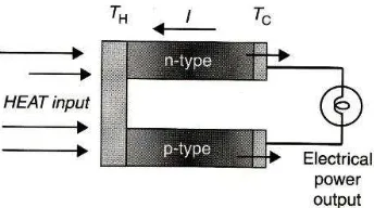
[image:23.595.198.370.343.439.2]The important parameters in thermoelectric power generator (TEG) can readily be derived by considering the simplest generator consisting of a single thermocouple with thermo elements fabricated from n-type and p-type semiconductors as shown (refer figure 2.1):
Figure 2.1: The Seebeck Effect (Source: Rowe (2006))
TEG consists of three main components, it is:
a. Hot-side heat exchanger b. Cold-side heat exchanger
c. Thermoelectric materials (TEMs)
2.4.1 Hot-side Heat Exchanger
9 2.4.2 Cold-side Heat Exchanger
[image:24.595.162.516.217.459.2]The cold-side heat exchanger is to dissipating heat from TEM to prevent damage on TEM due to high temperature, refer Figure 2.2 for schematic configuration of waste heat exchanger.
Figure 2.2: Schematic Construction of a Typical TEM (Source: www.tellurex.com (2009))
2.5 A Thermoelectric Application to Vehicles