VECTOR CONTROLLED DRIVES OF PERMANENT MAGNET
SYNCHRONOUS MOTOR USING Pl SPEED CONTROLLER FOR LONG
CABLE APPLICATION
CHEOK YONG SENG
ZULKIFILIE IBRAHIM
(2011 IEEE Student Conference on Research and Development (SCORED 2011), 19-20 December 2011, Putrajaya, Selangor)
UNIVERSITI TEKNIKAL MALAYSIA MELAKA
Vector Controlled Drives of Permanent Magnet
Synchronous Motor Using PI Speed Controller for
Long Cable Application
Cheok Yong Seng, Zulkifilie Ibrahim
Faculty of Electrical Engineering, Universiti Teknikal Malaysia Melaka, Malaysia.
セ「ウエイ。」エM This paper present a vector controlled drives of Permanent Magnet Synchronous Motor (PMSM) by using Proportional-Integral (PI) Speed controller for long cable ipplication. As known, long cable caused an over voltage problem at motor terminal and could be double from the pulse rntput voltage at inverter terminal. This caused instability of the ;peed performances. PI speed controller is implemented to drive
1 PMSM with different cables length to investigated the speed
performances, load disturbances and parameter variations of the ;ystem. Hysteresis current controller is used for inner loop :urrent control and PI controller for outer loop speed control. Simulation results are provided to show performances on iifferent cable length driving a PMSM.
Keywords-Proportional-Integral (Pl) Controller Speed ::ontroller, Vector Control, Permanent Magnet Synchronous Motor, long Cable, Hysteresis Current Controller
I. INTRODUCTION
Fan drives play an important role in underground mines, Jroviding fresh airflow in very long galleries. In this ipplication, for controlled staring as well as for airflow ·egulation, adjustable speed fan drives are applied [l]. The nain caused the winding failures due to overvoltage resonance rnd reflection phenomena. The problem solved with filter
nstalled and the system show failure free with good Jerformances and enhanced reliability [2].
The development of advanced power electronic switching Jperation has improved the performances of pulse-width i1odulated (PWM) of the adjustable speed drives (ASD). Switching frequencies of 2 to 20 kHz are common with
nsulated fate bipolar transistor (IGBT) technology for power evels up to 800kW. Many new and retrofit industrial ASD ipplications required that the inverter and the motor at ;eparate locations, often resulting in long cable lead of 50 -SOOft. It is well known that long leads contributed to over voltages at the motor terminals and thus increased dv/dt of :iver 600V/us which can damage the motor winding insulation md lead to premature motor failure [3]. Another important ASD application issue where increased losses in the motor/drive system and the possible need for de-rating when long cable lengths are required.
Variable speed drives of induction motors are generally used in many industries. One of such example is the induction-jriven fan in the environment control system of livestock
Cheok Yong Seng is MSc student in Faculty of Electrical Engineering, University Teknikal Malaysia, Malacca. (e-mail: [email protected])
Zulkifilie Ibrahim is with Faculty of Electrical Engineering, Universiti reknikal Malaysia Melaka, Malaysia. (e-mail: [email protected]).
closed farm. All the fans in the farm would be spun at the same speed but unfortunately the locations between them are sometime long in a possible range of 50 - 200 meters. The known problems of long cable usage lead to serious damage on the motor insulation and eventually it will reduce the life time of motor [4]. Because the high and fast voltage rise (dv/dt) in PWM inverter voltage waveforms caused the over-voltages at motor terminals when using long cables [5].
From previous literature review, many investigation and improvement done on long cable overvoltage problems, but in this paper focused on different cables length in term of the speed response, overshoot, rise and settling time, load disturbances and parameter variation on PMSM by using PI speed controller.
II. PMSM DYNAMICS
The machine model for the PMSM on the synchronously rotating d-q reference frame can be represented as [6]:
Where: icts, iqs Lcts,Lqs
rs
'Pr
Wr
V qs
=
r Jqs+ p lf'qs+ Wr lf'cts ( l) V ds=
r sicts+ p lf'cts -Wr 'Pqs (2)lJ1 qs
=
Lqsiqs (3)lJ1 ds
=
Lctsids +'Pr
(
4) Te=
G)
HセI@
['Pr
iqs + (Lcts - Lqs)icts iqs] (5)Te=Jpwr+Bwr+TL (6)
: d-q axis stator currents : d-q-axis inductances : stator resistance
: constant magnet flux linkage : motor speed
: number of pole : load torque
: damping co-efficient : rotor inertia
: electromagnetic torque
d for the inside buried, the cross axis of main inductance is セセエ@ equal (La セ@ Lq)· From the equation (5) show the torque depend on the mductances (La, Lq), type of rotor, magnet flux the permanent magnet mount on the rotor and number of
セ@ h 1 .
le With La = Lq, t e e ectromagnet1c torque can be po .
expressed as
(7)
An optimal efficiency PMSM is to ensures that stator current phasor contains only a quadrature axis component iq. This is analogous to the separately excited DC machine, where this is achieved by consecutive switching of the armature coil through the commutator [7].
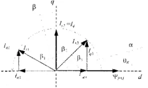
Figure I. Different locations of the stator current vector.
General expression of the torque can be written as
(8)
In the Figure 1 shown how the Iq is changing with the change
セヲ@ I, position, which results in a change in angle セN@ To Khieved maximum torque can be obtained with an angle
e
= 90°, this mode of operation gives the maximum torque Jer ampere of stator current and a high efficiency[?].III. SYSTEMS DESCRIPTION
4. PMSM drives system
A speed control system of the vector controlled PMSM irive is illustrated as Figure 2. Data of the motor used are given n Table I. The rotor speed, Wr is compared with w,* and the ·esulted error is processed in the controller. The output of :ontroller is reference torque, T* which is then has been imited by a limiter in order to generate the q-axis reference :urrent, iqs *. (Refer to Figure 3). Meanwhile, d-axis reference :uiTent, icts * is set to zero. Both d-axis and q-axis stator currents
セ・ョ・イ。エ・@ three phase reference currents (ia *, ib * and ic *) hrough Park's Transformation which are compared with ensed winding currents (i., ib and ic) of the PMSM. The :urrent errors are fed to hysteresis current controllers which '.enerate switching signals for the voltage source inverter. lhus, by obtaining winding currents of the system, the speed esponse is obtained.
iq:; ---i
w'·
J--p
1-___.. Vector
1
1 ,
"'\e セi、NL@
-+ ᄋイ。ョウセ@
( j Contra ler • .
1
L..._ 2/1
w,· ---+ _ _ 1
·,s'oO
Hysteresis Current
Controll€f 1 セN@ PMSM
8.
®
Figure 2. Configuration of Pl based vector controlled PMSM drive for long cable application
MMセ@
... G>
セNZᄋNM
..
。セᄋN@
セMサ^@
f
·j
D
I • t
i,•
Figure 3. PI Controller with Limiter
セN\NB@
,_
エMセエMMMセセMMャセセセNNNNN。N@Figure 4. Hysteresis Current Control
[image:3.595.273.519.27.123.2] [image:3.595.56.204.195.283.2] [image:3.595.285.505.227.474.2]the phase current within the hysteresis band. The phase currents are, therefore, approximately sinusoidal in steady state. The smaller the hysteresis band, the more closely do the phase currents represent sine wave. Small hysteresis band, however, imply a high switching frequency, which is a practical limitation of the power device. Increased switching frequency also implies increased inverter losses.
TABLE!. PMSM TEST MOTOR
Parameter Value
Maximum torque 10.8 Nm
Rated torque 3.6Nm
Rated current 6.29 A Maximum current 16A
Rated speed 418 rad/s ( 4000rpm) Inertia 0.000553 kgm2
Stator winding resistance 2.2n
Inductance 8.2mH
Voltage Constant 57.5 Vpk/krpm
Pole pairs 2
Voe 300V
B. High-frequency Cable Modeling
The cable parameter are estimated by using equations related to the geometrical configuration of the cable were found to be vastly different than actual parameter values because they do not include the frequency dependency in the calculation. Therefore, the cable parameters are estimated through experimental analysis by checking the frequency response of the power cable impedance. Two types of tests have been carried out : measurement of short circuit and open circuit impedances. [9]
The conventional 2nd order per-section model is commonly L1sed to represent cables as shown in Figure 5 (a) [IO], [I I]. The advantage of 2nd-order per-section model is its simplicity. However, the disadvantage of the conventional cable model is that it doesn't represent the cable frequency-dependent phenomena such as skin and proximity effects, dielectric losses, etc. The parameters of the conventional model are also difficult to measure accurately as the cable resonant frequency depends on cable characteristics and length. An improved cable model was proposed in [9], which can represent the jielectric losses using a higher-order parallel branch as shown in Fig. 5 (b ). Further improvements are proposed in this paper in order to include the skin and proximity effects. Such effects are not taken into account with the use of first-order series branch. Therefore, a high order model is proposed in Figure 5 (c). This section model combines the parallel branches as proposed in [9] and utilizes higher-order series braches to represent the skin and proximity effects.
(a) B+C (b) A B+C
"
(c)Figure 5. 2"ct order per-section cable model
The parameters of the proposed cable model in Fig. 5 (c) are identified from the cable SC and OC impedances ZSC and
ZOC. For the measurements of ZSC and ZOC, an HP/Agilent 4294A impedance analyzer [ 12] is used to evaluate the impedances in the range from I 00 Hz to 10 MHz. The fonnulas for cable parameter calculation are given as below. [13]
Ls!= Lsc-uF Ls2 = Lsc-LF- Ls1
Rs I = IZsc -LF I cos( 8 sc-LF )
Rs2
=IZ:1-c-HFI
cos( 8 sc-HF )-Rs1 Cp1 =Coe-HFCp2
=
Coc-LF- cplRp1 = IZoc-LF
I[
cos( 8 oc-LF )f1 Rp111p2 = IZoc-Hrl[ cos( 8 oc-HF)r
1Rp2 =
l<
Rpli1p2r
1-<
Rp,r
1r
1(9) (I 0) ( 11) (12) (13) (14) (15) (16) (17)
[image:4.598.25.227.105.287.2]Table II. From the proposed cable model and the calculated parameters, the cable SC and OC impedances are reproduced and are superimposed with the measured characteristics, the results fitted by the proposed equivalent circuit of Figure 5 ( c) are in good agreement with the measured characteristics for the actual cable segment. [ 13]
TABLE II. PROPOSED CABLE PER-METER PARAMETERS
Parameter Value
Rsl
21 mnRs2
271.2 mnRpl
22MQRp2
IOOKQLsl
451.8 nHLs2
89.32 nHCpl
79.6 pfCp2
34.11 pfIV. RESULTS
The study of vector-controlled PMSM drive with implementing Design case (1 meter), 200 meter and 400 meter cable of PI speed controller is carried out in the MATLAB (Simulink) program. All study based on rated value of the test motor model as shown in Table I and cable parameter as show in Table II. The investigations are aimed at studying the speed responses of the PI controller with implementation of different cable length connected to PMSM.
time{s)
(a)
time(s)
(b)
Design Case
- - - 2 0 0 m
400m
Desigo(ase
- - i o o i n
<OOm
t1me(s)
(c)
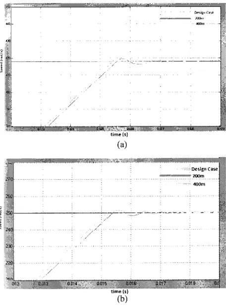
Figure 6. Comparison of speed responses obtained by different cable length during start-up for 3 different speeds : (a) at rated 41 Srad/s (b) at 250rad/s (c) at 125rad/s
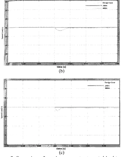
Figure 6 presents a small overshoot of 0.4% rated speed (2rad/s) during start-up from standstill and accelerated to the speed command without load. The result show the speed response on the different cable length during start up condition, the longer of the cable length connected to motor caused rise time increased. After the responses settling down at the speed command, the system is loaded with rated load torque which is 3.6Nm at instant time, t = 0.04 sec and the results are showed in Figure 7. The speed controller reject load disturbance rapidly without overshoot and almost zero steady state error at rated speed 418rad/s. The results show speed controller reject load disturbance faster at shorter cable length and the steady state error increased when decrease speed command to 250rad/s and 125rad/s. Figure 8 can be clearly seen that shorter cable length connected to motor produces faster undershoot response compared to longer cable length.
time(s)
[image:5.595.280.507.6.149.2] [image:5.595.23.232.100.253.2] [image:5.595.2.230.362.672.2] [image:5.595.282.509.397.547.2]tlme(s)
(c)
:igure 7. Comparison of speed responses to step rated load torque 1pplication obtained at different cable length for 3 different speeds : a) at rated 418rad/s (b) at 250rad/s ( c) at J 25rad/s
time(s)
dᆪセゥァョ@ cN[ュセ@
MᄋセセセBᄚBNRPPイョ@
Figure 8. Comparison of speed responses obtained by different cable length during step down 50% reduction at speed command
V. CONCLUSION
This paper presents results of a vector controlled drives of )MSM using PI Speed controller for long cable application in 1igh performance drives. 3 types of cable length : Design case
I meter), 200meter and 400meter are studied. Performance of lifferent cable length is studied for large step speed command 'rom standstill with rated and, load rejection transients and ·everse speed command. The simulation study is realized in \.1A TLAB environment. The comparison of speed )erfonnances over the several tests shows that longer cable :onnected to motor caused the speed performance degrade due o losses on long cable.
REFERENCES
[I] R. Hanna and S. Prabhu, "Medium-voltage adjustable -speed drives Users' and manufacturers experiences," IEEE Trans. Ind. Appl., vol. 33, no.6, pp.1407-1415, NovJDec. 1997.
[2] J. Rodriguez, J. Pontt, C. Silva, R. Musalem, P. Newman, R. Vargas, and S. Fuentes, "Resonances and overvoltages in a medium-voltage fan motor drive with long cables in an underground mine," IEEE Trans. Ind.
Appl., vol. 42, no. 3, pp. 856-863, May/Jun. 2006.
[3] E. Matheson, A. Von Jouanne, and A.Wallace, "Evaluation of inverter and cable losses in adjustable speed drive applications with long motor leads," in Proc. IEDM, May 9-12, 1999, pp. 159-161.
[4] B.Basavaraja and D.D.S.S.Siva Sarma, "Application problem of PWM AC drives due to long cable length and high dv/dt," Research Scholar.NIT Warangal/Associate,2006.
[5] B.Basavaraja and D.D.S.S.Siva Sarma, "Modelling and simulation of dv/dt filters for AC drives with fast switching transients," Department of Electrical Engineering. NIT Warangal, lndia,2006.
[6] Zare.J, and Askari.M, "Vector Control of permanent magnet synchronus motor with surface magnet using genetic algorithm fuzzy logic controller" in 45lh Intl. UPEC, Aug 31 - Sept 3 2010, pp. 1-4.
[7] Marek.S, Valeria.H and Marek.F, "Permanent magnets synchronous motor control theory," in Journal of ELECTRICAL ENGINEERING, VOL. 58, NO. 2, 2007, pp. 79-84
[8] Z. Li and S. Fengchun, "Torque control of dual induction motors independent drive for tracked vehicle," in 2008 l 0th Intl. Conf. on Control, Automation, Robotics and Vision, 2009, pp. 68-72.
[9] A. F. Moreira, T. A. Lipo, G. Venkataramanan, and S. Bernet, "Highfrequency modeling for cable and induction motor overvoltage studies in long cable drives," IEEE Trans. Ind. Appl., vol. 38, no. 5, pp. 1297- 1306, Sept/Oct. 2002.
[IO] N. Aoki, K. Satoh, A. Nabae, "Damping circuit to suppress motor terminal overvoltage and ringing in PWM inverter-fed AC motor drive systems with long cable leads," IEEE Trans. Ind. Appl., vol. 35, no. 5, pp. 1014-1020, Sept/Oct. 1999.
[I I] R. Vargas, and S. Fuentes, "Resonances and overvoltages in a
medium-voltage fan motor drive with long cables in an underground mine," IEEE
Trans. Ind. Appl., vol. 42, no. 3, pp. 856-863, May/Jun. 2006.
[12] E. Matheson, A. Von Jouanne, and A.Wallace, "Evaluation of inverter and cable losses in adjustable speed drive applications with long motor leads," in Proc. IEDM, pp. 159-161, May 9-12, 1999.
[image:6.595.4.237.10.314.2]