‘I hereby declare that I have read this dissertation and found its content and form to meet acceptable presentation standards of scholarly work for the award of
Bachelor of Mechanical Engineering (Thermal-Fluid)’
Signature : ………
Supervisor : ………
THE PERFORMANCE OF THERMOELECTRIC POWER GENERATOR (TEG) BASED HI-Z THERMOELECTRIC MODULES
MOHD HIDAYAD BIN ZULKIFLI
A report submitted in partial fulfillment of the Requirement for the award of the degree of Bachelor of Mechanical Engineering (Thermal-Fluid)
Faculty of Mechanical Engineering Universiti Teknikal Malaysia Melaka
ii
I hereby, declare that this thesis entitled “The performance of thermoelectric power
generator (TEG) based Hi-Z thermoelectric modules” is the result of my own research
except as cited in the references.
Signature : ...
Name : MOHD HIDAYAD BIN ZULKIFLI
iii
iv
ACKNOWLEDGEMENT
In the name of Allah, The Most Gracious, The Most Merciful. First and foremost, I thank to Allah for giving me this opportunity to complete my report successfully.
First of all, my heartiest appreciation to my final year project supervisor, Mr. Mohamad Firdaus Bin Sukri for his guidance, advice, support which have put me in the performance of thermoelectric power generator (TEG) based Hi-Z thermoelectric modules of this project. His idea, experience and knowledge had been aspiring to me abundantly.
v
ABSTRACT
vi
ABSTRAK
vii
TABLE OF CONTENTS
CHAPTER TITLE PAGE
DECLARATION ii
DEDICATION iii
ACKNOWLEDGEMENT iv
ABSTRACT v
ABSTRAK vi
TABLE OF CONTENT vii
LIST OF TABLE xi
LIST OF FIGURE xii
LIST OF SYMBOLS xiv
LIST OF APPENDICES xv
CHAPTER I INTRODUCTION 1
1.1 Introduction into General Topic 1
1.2 Thermal Energy 2
1.3 Basic of Heat transfer 3
1.3.1 Heat Transfer Mechanisms 3
1.4 Direct Energy Conversion 3
1.5 Problem statement 4
1.6 Objectives of the Study 5
viii
CHAPTER TITLE PAGE
CHAPTER II LITERITURE REVIEW 6
2.1 Introduction 6
2.2 Heat Transfer Process 6
2.2.1 Conduction 8
2.2.2 Radiation 9
2.2.3 Convection 10
2.3 Thermoelectric 11
2.3.1 Competitive Advantages 11
2.3.2 Advantages and Disadvantages 12 of Thermoelectric Technology
2.4 Thermoelectric Generation 12
2.5 Thermoelectric modules 13
2.5.1 The HZ-20 thermoelectric module 14 2.5.2 Commercial Thermoelectric 15
Modules
2.6 The performance of TEG 16
2.7 Thermo Generators 16
2.7.1 Uses 17
2.7.2 Automotive Thermoelectric 17 Generators
2.7.3 Operation principles 19
2.7.4 Calculation for the 19
performance of the TEG
2.8 New Knowledge about Thermoelectric 21 Materials Could Give Better Energy
Efficiency
2.9 The 4G13 Mitsubishi Orion engine 22
2.9.1 Performance 22
ix
CHAPTER TITLE PAGE
2.10 Cooling System 23
2.11 Automobiles Radiator 25
2.12 Dynamometer 26
2.12.1 SF-902 Engine Dyno 27
CHAPTER III METHODOLOGY 29
3.1 Introduction 29
3.2 Flow Chart of Methodology 30
3.3 Analysis of the Best Location of 33 Thermoelectric Generator (TEG)
using with selected compartments of Engine
3.3.1 Locations those chosen to place 38 the TEG
3.4 Experiment of Dyno Testing for 1.3L 37 4G13 Engine
3.4.1 Thermoelectric (TEG) 37
3.4.2 SF-902 engine Dyno 38
3.4.3 The TEG will produce electricity 39 power when used on 1.3L
4G13 Engine
3.4.4 Procedures of Dyno Test 40
Experiment (engine speed, rpm)
3.5 Other Apparatus 43
3.5.1 Thermocouples 43
3.5.2 Multimeter 44
x
CHAPTER TITLE PAGE
CHAPTER IV RESULTS 46
4.1 Introduction 46
4.2 Result 46
4.2.1 Sample calculations 47
4.2.1 Theoretical Data 49
4.2.2 Experimental Data 51
4.2.3 Comparison between theoretical 52 and experimental data
CHAPTER V DISCUSSION 54
5.1 Discussion 54
5.1.1 Theoretical 54
5.1.2 Experimental 56
5.1.3 Comparison between theoretical 57 and experimental
CHAPTER VI CONCLUSION AND RECOMMENDATION 59
6.1 Conclusion 59
6.2 Recommendation 60
REFERENCE 61
BIBLIOGRAPHY 62
xi
LIST OF TABLES
NO. TITLE PAGE
2.1 Advantages and Disadvantages of Thermoelectric Technology 12
2.2 Properties of the 19 Watt modules, HZ 20 14
(Source: Hi-Z technology, (2006))
3.1 Description of aspects to choose the best location 33 3.2 Descriptions of aspect, score and criteria to choose 35
the best location for TEG
3.3 Total score of the criteria 36
3.4 Descriptions of the dimension for TEG 37
3.5 Descriptions of the fin and modules for TEG 38
3.6 Experimental table for Coolant Temperature 42
3.7 Experimental table for resistance and voltage 42
4.1 Theoretical data for Temperature Difference and Power 48
4.2 Experimental data for Coolant Temperature 50
4.3 Experimental data for resistance, voltage and power 50 4.4 Experimental data for Power with temperature difference 50 4.5 Experimental data for Power (theoretical and experimental) 52
xii
LIST OF FIGURES
NO. TITLE PAGE
2.1 Conduction, convection and radiation 7
(Source:Oklahoma Climatological Survey, 1996)
2.2 Frying pan set 8
(Source: Physical Science, Transfer of Energy, (1998)
2.3 The transfer of heat from an object 9
(Source: Morena, transfer of heat (1995))
2.4 Heat-transmittance 10
(Source:sophie, (2009))
2.5 The Seedback effect 12
(Source: D.M. Rowe (2006))
2.6 Hi- Z Thermoelectric Modules 13
(Source: Ferrotec, (2006))
2.7 Heat absorbed and heat rejected side in thermoelectric modules 15
(Source: Melcor, (2000))
2.8 ATEG converts engine waste heat 18
(Source: Eere, Vehicle Technologies (2008))
2.9 4G13 Engine 23
(Source: Gasgoo, Global Auto Source (2000)) 2.10 Diagram of a cooling system: how the plumbing is connected 24
(Source: How Stuff Works.com, (2000))
2.11 Illustration of Radiator 25
xiii
NO. TITLE PAGE
2.12 Illustration of Dynamometer 26
(Source: Sweethaven, Automotive Systems (2002))
2.13 The SuperFlow SF-902 28
(Source: www.superflow.com, (2000))
3.1 Flow chart of methodology used throughout this experiment 30
3.2 Location A 34
3.3 Location B 34
3.4 Location C 34
3.5 Thermoelectric Generator (TEG) 38
3.6 SF-902 Engine Dyno 39
3.7 Engine-Dyno With TEG 40
3.8 Thermocouple 43
3.9 Multimeter 44
3.10 Tachometer 45
4.1 Graph Total Power versus Engine Speed for theoretical data 49 4.2 Graph Power versus Temperature difference for theoretical data 49 4.3 Graph Power versus Engine Speed for experimental data 51 4.4 Graph Power versus Temperature difference for experimental data 51 4.5 Graph Power versus Engine Speed Comparison with 52
Theoretical and Experimental
4.6 Graph ΔPower versus Engine Speed 53
4.7 Graph Efficiency versus Engine Speed 53
A1 Hi-Z’s HZ20 Thermoelectric module power curves 64 A2 Hi-Z’s HZ20 Thermoelectric module efficiency curves 64
C1 The overview during experiments 66
F1 Hi-Z Module Properties Software 70
F2 Data module when input temperatures 70
G1 Properties table of water (Source: Heat Transfer, (2002)) 71
xiv
LIST OF SYMBOLS
DC = Direct Current T = Temperature, ˚C
I = Current
ΔT = temperature difference, ˚C Qc = cooling power, W
V = voltage, V α = coefficient
σ = electrical conductivity k = thermal conductivity R = resistance, ohm Gfh = volume flow rate, m
2
/s ρfh = fluid density
Cfh = specific heat capacity.
Δtfh = temperature drop
η = efficiency
Bi2Te3 = Bismuth telluride
P = Electric Power
W = Power Output
xv
LIST OF APPENDICES
NO. TITLE PAGE
A Temperature Dependence 64
B HZ-20 Thermoelectric Module 65
C The overview during experiments 66
D Thermoelectric Materials 68
E Thermoelectric Generator Manufacturers 69
F Hi-Z Module Properties Software 70
G Properties table of water (saturated liquid) 71
1
CHAPTER I
INTRODUCTION
1.1 Introduction into General Topic
Many years ago, energy helps us to do things. It gives us light. It warms our bodies and homes. It bakes cakes and keeps milk cold. It runs our TVs and moves our cars. It makes us grow, move and think. Energy is the power to change things. It is the ability to do work.
The energy is used to produce heat and keeps our bodies warm. Sometimes, when run or work hard it can generate heat and feel really hot. In the winter, our jackets and blankets help to keep warm of the body. The energy is stored in plants and other things used to produce heat. The process of burning wood and natural gas to cook meals can make the house warm. Factories burn fuel to manufacture the products and also the power plant burn coals to produce electricity.
2
1.2 Thermal Energy
Thermal energy is generated and measured by heat. It is caused by the increased activity or velocity of molecules in a substance, which in turn causes temperature to rise accordingly. There are many natural sources of thermal energy on Earth, making it an important component of alternative energy.
The laws of thermodynamics explain that energy in the form of heat can be exchanged from one physical object to another. For instance, putting fire under a pot of water will cause the water to heat up as a result of the increased molecular movement. In that way, the heat, or thermal energy, of the fire, is partially transmitted to the water.
Understanding the principles of thermodynamics has allowed human beings to harness natural sources of heat to create thermal energy out of a variety of sources. The sun, ocean, and geothermal sources such as geysers and volcanoes, can all be sources of thermal energy. As humans attempt to turn to sustainable forms of alternative energy instead as fossil fuel resources become depleted, much attention has been focused on improving methods of harnessing thermal energy to power human activity.
1.3 Basic of Heat Transfer
In the simplest of terms, the discipline of heat transfer is concerned with only two things: temperature, and the flow of heat. Temperature represents the amount of thermal energy available, where as heat flow represents the movement of thermal energy from place to place.
3
Several material properties serve to modulate the heat transferred between two regions at differing temperatures. Examples include thermal conductivities, specific heats, material densities, fluid velocities, fluid viscosities, surface emissivities, and more. Taken together, these properties serve to make the solution of many heat transfer problems an involved process.
1.3.1 Heat Transfer Mechanisms
Heat transfer mechanisms can be grouped into 3 broad categories: Conduction
Convection Radiation
1.4 Direct Energy Conversion
The energy conversion devices that have been in use for a long time are those that accept energy heat and produce mechanical work which is transformed into electrical power for distribution at last. Direct energy conversion device convert naturally available energy into electricity without an intermediate conversion into mechanical work. The energy source may be thermal, solar or chemical. Until now their uses have been confined to small scale special purpose applications, since the voltage output available with them is rather small.
4
Due to intermediate steps of conversion, efficiency is reduced to great extent. Great attempts have been made during the last two decades to convert thermal, electromagnetic or chemical energy directly into electrical energy raising the thermodynamic efficiency to 60 to 75%. Such systems are called direct energy converters.
1.5 Problem statement
More than 60% of the energy that goes into an automotive combustion cycle is lost, primarily to waste heat through the exhaust and radiator system. This is particularly true of automobiles, where two-thirds of the fuel is emitted unused in the form of heat. About 30 percents are lost through the engine block and a further 30 to 35 percents as exhaust fumes. It is clear that when a vehicle is loaded with a thermoelectric power generator (TEG), it is possible to generate electricity by using a “waste heat recovery” concept. Nevertheless, the installation of TEG will disturb the fundamental principle of the vehicle system operation itself. In other hand, the investigation of the performance of this TEG is very important to justify the suitability of the usage. By this reason a research has been proposed and will be conducted to investigate the performance of TEG when being used with 1.3L 4G13 engine.
1.6 Objectives of the Project
5
1.7 Scopes of the Project
The scopes of this project are as follows:
1. Literature review on TEG, Thermoelectric Modules, heating transfer process etc. 2. Conduct analysis to choose the best location for TEG (used with selected
compartments of engine).
3. Conduct experimental study on 1.3L 4G13 engine by using ready to use TEG. 4. Manipulate data collected from experimental study to determine the performance
6
CHAPTER II
LITERATURE REVIEW
2.1 Introduction
In this chapter there will be the literature review of this project. This chapter consist briefly the heat transfer process, basic of thermoelectric modules, studies about the TEG, 1.3L 4G13 engine, cooling system and Dynamometer.
2.2 Heat Transfer Process
7 During processing, temperatures may change and therefore the rate of heat transfer will change. This is called unsteady state heat transfer, in contrast to steady state heat transfer when the temperatures do not change. An example of unsteady state heat transfer is the heating and cooling of cans in a retort to sterilize the contents. Unsteady state heat transfer is more complex since an additional variable, time, enters into the rate equations.
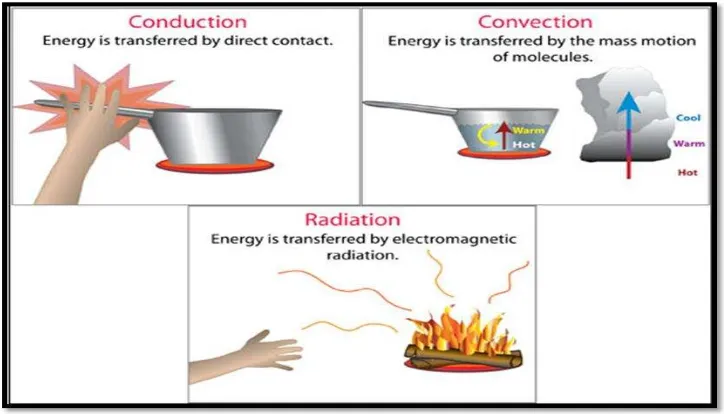
[image:23.612.146.508.243.450.2]Heat can be transferred in three ways: by conduction, by radiation and by convection.
Figure 2.1: Conduction, convection and radiation (Source:Oklahoma Climatological
Survey, (1996))
8
2.2.1 Conduction
In heat transfer, conduction is the transfer of thermal energy between neighboring molecules in a substance due to a temperature gradient. It always takes place from a region of higher temperature to a region of lower temperature, and acts to equalize temperature differences [4]. Conduction takes place in all forms of matter, viz. solids, liquids, gases and plasmas, but does not require any bulk motion of matter. In solids, it is due to the combination of vibrations of the molecules in a lattice and the energy transport by free electrons. In gases and liquids, conduction is due to the collisions and diffusion of the molecules during their random motion. For example, a spoon in a cup of hot soup becomes warmer because the heat from the soup is conducted along the spoon. Conduction is most effective in solids-but it can happen in fluids. Conduction is one of the ways that energy is transferred from the earth's atmosphere to the air. Conduction is the process by which heat energy is transmitted through collisions between neighboring molecules [4].
That the energy is transferred by conduction and that the heat-transfer rate per unit area is proportional to the normal temperature gradient. When the proportionality constant is inserted,
(1)
[image:24.612.212.447.553.681.2]Where qx is the heat transfer rate, k is thermal conductivity and dT/dx is the temperature gradient in the direction of the heat flow.