UNIVERSITI TEKNIKAL MALAYSIA MELAKA
ATM SECURITY SYSTEM WITH GSM INTEGRATED
TECHNOLOGY
This report submitted in accordance with requirement of the Universiti Teknikal Malaysia Melaka (UTeM) for the Bachelor Degree of Electronics Engineering
Technology (Industrial Electronics) (Hons.)
by
SYAZWANI BINTI GHAZALI B071210017
881125265102
UNIVERSITI TEKNIKAL MALAYSIA MELAKA
BORANG PENGESAHAN STATUS LAPORAN PROJEK SARJANA MUDA
TAJUK: ATM Security System with GSM Integrated Technology
SESI PENGAJIAN: 2015/16 Semester 1
Saya SYAZWANI BINTI GHAZALI
mengaku membenarkan Laporan PSM ini disimpan di Perpustakaan Universiti Teknikal Malaysia Melaka (UTeM) dengan syarat-syarat kegunaan seperti berikut:
1. Laporan PSM adalah hak milik Universiti Teknikal Malaysia Melaka dan penulis. 2. Perpustakaan Universiti Teknikal Malaysia Melaka dibenarkan membuat salinan
untuk tujuan pengajian sahaja dengan izin penulis.
3. Perpustakaan dibenarkan membuat salinan laporan PSM ini sebagai bahan pertukaran antara institusi pengajian tinggi. atau kepentingan Malaysia sebagaimana yang termaktub dalam AKTA RAHSIA RASMI 1972)
(Mengandungi maklumat TERHAD yang telah ditentukan oleh organisasi/badan di mana penyelidikan dijalankan)
____________________
i
DECLARATION
I hereby, declared this report entitled “ATM Security System with GSM Integrated Technology” is the results of my own research except as cited in the references.
Signature : ………
Author’s Name : Syazwani binti Ghazali
ii
APPROVAL
This report is submitted to the Faculty of Engineering Technology of UTeM as a partial fulfilment of the requirements for the degree of Bachelor of Engineering Technology (Industrial Electronics) (Hons.). The member of the supervisory is as follows:
iii
ABSTRACT
iv
ABSTRAK
v
DEDICATIONS
Alhamdulillah, praise to Allah S.W.T. This thesis is dedicated to,
My beloved parents, My family, My supervisor,
My lecturers, And all my friends.
vi
ACKNOWLEDGMENTS
vii
List of Abbreviations, Symbols and Nomenclatures xii
CHAPTER 1: INTRODUCTION
2.1 Previous Project Study on The GSM Technology 8
2.1.1 Anti-Theft ATM Machine Using Vibration Detection Sensor 8 2.1.2 Development of Anti-Theft Vehicle & GPS Locator Using GSM 9
2.1.3 Anti-Theft Alarm System Using GSM 9
2.1.4 Automobile Anti-Theft System Based on GSM and GPS Module 9
2.1.5 Secured ATM transaction Using GSM 9
2.2 GSM Module 13
viii CHAPTER 3: METHODOLOGY
3.1 Introduction 26
3.2 Software Development 29
3.2.1 Installing the Arduino IDE Software 30
3.2.2 HyperTerminal Connection 31
3.3 Hardware Development 36
3.3.1 Main Controller Circuit using Arduino UNO 36
3.4 Measuring Vibration 38
4.2 The Project Hardware Analysis 43
4.2.1 Testing on the Functionality of the Vibrate Module Sensor 44 4.2.2 System Testing on the Main Function of the Hardware 47
4.2.3 Analysing the Network System of GSM 48
4.3 Discussion 52
CHAPTER 5: CONCLUSION AND FUTURE WORK
5.1 Conclusion 54
5.2 Future Works 55
APPENDICES 56
ix
Figure 2.1: The GSM Network Organization 12
Figure 2.2: GSM SIM900A module 13
Figure 2.3: SIM card 16
Figure 2.4: Arduino Uno Board Front View 17
Figure 2.5: Arduino Uno Board Back View 17
Figure 2.6: Arduino Board Specification 18
Figure 2.7: Limit Switch 23
Figure 2.8: Configuration of Limit Switch 23
Figure 2.9: Vibration Sensor Switch Module (SW-420 NC) 24
Figure 2.10: Example of the sketch coding block 25
Figure 3.1: Block diagram of ATM Security System with GSM Integrated
Technology 27
Figure 3.2: Project Methodology Flowchart 28
Figure 3.3: A simple LED blinking coding 30
Figure 3.4: Connection of Arduino Uno board with PC using USB cable 31
Figure 3.5: Checking for COM port 32
Figure 3.6: Run the HyperTerminal application 32
Figure 3.7: Display box of Connection Description 32
Figure 3.8: The COM port used is COM13 33
Figure 3.9: The display box to select connection channel 33
Figure 3.10: Selecting the bits per second (bps) 34
Figure 3.11: Selecting the Flow control option 34
Figure 3.12: Untick the ‘Echo typed characters locally’ 35 Figure 3.13: Testing the GSM module by using AT command to send and receive
x
Figure 3.14: Block diagram of ATM Security System with GSM Integrated
Technology 36
Figure 3.15: The direct connection of Arduino and GSM module 37 Figure 3.16: The graph of displacement of amplitude in one cycle time 38
Figure 4.1: Flowchart of the programming 42
Figure 4.2: The overall connection of the project hardware 43 Figure 4.3: The direct connection of vibration sensor with Arduino board 44 Figure 4.4: (a) Voltage value when external LED does not blinking, (b) Voltage
value when external LED blinking 45
Figure 4.5: Graph of voltage reading vs. potentiometer level 46 Figure 4.6: Monitoring the output state condition of the vibration sensor via serial
monitors 47
Figure 4.7: Connection of the whole system 48
Figure 4.8: The SMS received from the GSM module upon detection of robbery 48 Figure 4.9: (a) The minimum time taken, (b) The maximum time taken 49 Figure 4.10: The histogram of the frequency of SMS received by users by in a time
range 51
Figure 4.11: The histogram of the percentages of SMS received by users by time
xi
LIST OF TABLES
Table 2.1: GSM Module parameter and specification 13
Table 2.2: Lists of the AT Command 15
Table 2.3: Summary of Arduino UNO Board 18
xii
LIST OF ABBREVIATIONS, SYMBOLS AND
NOMENCLATURES
AT command - Attention command
ATM - Auto Teller Machine
BSC - Base Station Controller
BSS - Base Station System
BTS - Base Transceiver Station
CDM - C Cash Deposit Machine
CDMA - Code Division Multiple Access
DC - Direct Current
GPS - Global Positioning System
GSM - Global System Mobile
ICSP - In-Circuit Serial Programming
IDE - Integrated Development Environment
IMEI - International Mobile Equipment Identity
IR - Infrared
LED - Light Emitting Diode
MS - Mobile Station
MMS - Multimedia Message Service
NC - Normally Close
NO - Normally Open
PWM - Pulse Width Modulation
RF - Radio Frequency
RFID - Radio Frequency Identification
RX - Receiver
SIM - Subscriber Identity Module
SMS - Short Messaging Service
SS - Switching System
TX - Transmitter
1
CHAPTER 1
INTRODUCTION
This project of ATM Security System with GSM Integrated Technology is specially built to provide a security system for the auto-teller machine (ATM) with a high-tech security system from being robbed. It will use a wireless technology, which is GSM, and this is done by sending an auto-generated SMS to inform or alert police and bank security whenever ATM robbery occurs. This chapter will briefly discuss the general background of this project, its objectives, problem statement, scope of the project and project methodology.
1.1 Project Background
In this economically deteriorating world nowadays, the crime rate is getting worse. Under such circumstances, there are people who decide to do things that are against the law in order to get money; one of them is stealing people’s money by robbing the ATM.
In this proposed system, if the robber tries to steal the ATM, the sensor will detect the ATM machine is being stolen and the Arduino gets an interrupt through a switch mechanism connected to the system and commands the GSM module to send an SMS.
2 1.2 Problem Statement
Nowadays, in Malaysia, the numbers of ATM theft and robbery cases has been increasing. The problem was that whenever the incident occurs, the current ATM security system only gives out alarm warning siren sound at the exact location where the incident took place. Let say the incident took place at wee hours as an example in Figure 1.4, where nobody happens to be around the ATM. The triggered alarm will not be heard by anybody at that particular time, including the security guard. The robbers or the theft will just have to cut off the circuit connection of the alarm and continue to destroy or ran away with the ATM machine.
This deteriorating condition of robbery cases has made the bank losses public’s trust to save money in the bank. They also face with huge monetary losses whenever ATM was robbed.
Due to this problem, a new high-tech ATM security system is needed in order to help in reducing the increasing number of ATM robbery cases in Malaysia. This new high-tech security system introduced will be using GSM technology and equipped with two types of sensor. The GSM will act as an informer by sending notification SMS to bank authorised personnel and local law enforcement.
Compare to other network systems, the GSM which has worldwide coverage is believed to work effectively and efficiently in this new system. It is also hoped to be a new step in providing a better security system for ATM nowadays.
3
Figure 1.1: News article 1
[http://malaysianreview.com/5947/mesin-atm-dipecahkan-pencuri-bawa-lari-lebih-rm224570/]
Figure 1.1 shows a CCTV recording video of ATM machine were forced open by two thieves and an amount of more than RM 224,570.00 were taken away. The incident was reported taking place at a petrol station located at Persiaran Kewajipan, Subang Jaya.
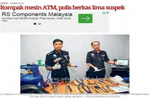
Figure 1.2: News article 2
4
Figure 1.2 above shows the victory of police forces in capturing five suspects, including women who were believed involved in two incidents of ATM and CDM robbery attempt at Plaza Damai, Luyang and Plaza Alamesra in Kota Kinabalu, Sabah. All suspects were captured in a house at Likas Court, Jalan Tuaran.
Figure 1.3: News article 3
[http://www.thesundaily.my/news/1185298]
5
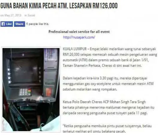
Figure 1.4: News article 4
[http://www.kualalumpurpost.net/guna-bahan-kimia-pecah-atm-lesapkan-RM126000/]
The news article of Figure 1.4 stated that four men took away RM 126,000 by using oxyacetylene gas to force open the ATM machine. The incident was reported took place at Taman Shamelin Perkasa, Cheras, Kuala Lumpur at around 3.30 a.m.
1.3 Objective
The main objective for this project is to design and develop a security system for the ATM machine to prevent it from being robbed. This project includes the research and study on how a sensor and GSM module would work. The objectives of this project are:
To design and develop a compatible system which can help to assist in the issue of ATM robbery or stolen ATM
6 1.4 Project Scope
The scope of this project will focuses on how the ATM’s security system works. A model or a prototype will be made by using Arduino, vibration alarm sensor module, limit switch sensor and GSM module demonstrate how the circuit functioning. The project circuit also will be equipped with Alarm LED and a buzzer. The circuit will function when the vibration sensor detects any excessive vibration occur towards the ATM machine body. This will trigger the vibration sensor to send signal to the Arduino. The limit switch sensor also will be placed underneath the ATM body and also at the ATM’s door.
When the ATM machine is lifted up to a certain height, the connection of the limit switch will be activated and sends an input voltage signal to the Arduino. The Arduino will process the input signal and sends an output signal to the alarm LED and buzzer. The buzzer will sound on and light up the alarm LED. At the same time, the GSM is activated by the signal from the Arduino and will send SMS to the bank security and the police.
1.5 Project Methodology
This project is carried out into two main parts which are the stages of system designing and evaluation of the performance as follows:
1. Design of the system
i) Electrical circuit construction and simulations: Arduino UNO board and Arduino IDE software
ii) Hardware construction and integration by doing the connection and soldering of the components.
2. Evaluation of the product performance
i) Product testing and analysis: Sensors sensitivity to detect the changes on its connection.
7
1.6 Project Outline
Chapter 1 consists of the introduction of the project, including the project background and problem statement. Besides that, the objectives, scope of the project, and methodology of the project also are discussed and mention in this chapter. Then, a little explanation related to this project is discussed.
Chapter 2 covers on the literature review of the project. The literature review was obtained from journal paper, article, books and technical papers in order to get deep knowledge. The literature review includes three parts which are previous project study, hardware development and software development.
In chapter 3, project methodology is fully covered with discussion and explanation about the methods and approaches applied in this project. The method of designing ATM Security System with GSM Integrated Technology includes the electrical connection process and simulation. All steps of the design are explained in detail in this chapter.
The result of this simulation is analysed and explained in a very detailed statement in Chapter 4. The findings on analysis results are presented in this chapter.
8
CHAPTER 2
LITERATURE REVIEW
The literature review is done by gathering information about this project from journal, articles, books and papers to gain deeper knowledge. This chapter describes some literature related to the information which utilizing the Global System of Mobile Communications (GSM) and the Arduino. Basically, this chapter is divided into two sections which are the hardware development and software development. The literature review is necessary before initiating the project and literature researches regarding the project are important in understanding the concept of the overall project.
2.1 Previous Project Study on the GSM Technology
Some case study and review of previous researches is performed to gain more information and understanding on GSM module. Previous study shows that there are many projects that are based on GSM applications that can be revised as a guideline towards completing this project.
2.1.1 Anti-Theft ATM Machine Using Vibration Detection Sensor
9
development will profoundly affect the development of national economy and national defence science and technology.
2.1.2 Development of Anti-Theft Vehicle & GPS Locator Using GSM
Nurul Afiza binti Othman (2012) developed an anti-theft vehicle and GPS locator using GSM. This project mainly focuses on the alarm system of safety element where it will trigger the alarm if there is any invasion or theft occurred. This alarm system introduces a combination of multiple electronic devices. When there is a change of electrical capacitance due to human touch, the detector will be activated and send a warning SMS to users.
2.1.3 Anti-Theft Alarm System Using GSM
Normaizatul Nabila binti Zakari (2012) has design and develop a GSM and GPS tracking system to prevent vehicles from stolen. It functions to enable and disable a vehicle using hand phone if the vehicle gets stolen. An SMS warning will be sent to user if someone trying to open the car door of the vehicle.
2.1.4 Automobile Anti-Theft System Based on GSM and GPS Module
Jian Ming, Li Jie and Guang Hui (2012) have developed an automobile anti-theft system based on GSM and GPS module. This system is developed based on the high speed mixed type single-chip C8051F120 and detect automobile stolen to the automobile owner by vibration sensor. Automobiles location can be obtained with the GPS module integrated in the anti-theft system. The system also can keep in touch with the automobile owner via the GSM module to monitor the safety and reliability of the automobile.
2.1.5 Secured ATM transaction Using GSM
10
must feel safe and the ATM’s vault must be secure from theft. New features have been introduced to the card user and account holder that allows the accessing of the account. Any unresolved acceptance messages will result in the denying of the access. Other features that has been installed together is the usage of infrared (IR) based sensor setup. Any misusing of the cards will result in notification SMS will be sent to both user and the bank manager through an RF wireless communication hardware, but it limits the hardware functionality, for example sending or receiving of SMS.
A GSM module is a module which accepts a SIM card and functions like a mobile phone because it operates over a subscription to a mobile operator. Basically, a GSM uses a circuit switching. This circuit switching allows a path to be established between two devices and when the two devices are connected, a constant stream of digital data is relayed. Three major systems in GSM networks, which are the Switching System (SS), The Base Station (BSS) and the Mobile Station (MS) (K. Maurya, M. Singh, and N. Jain).
a) The Switching System (SS)