UNIVERSITI TEKNIKAL MALAYSIA MELAKA
IMPROVEMENT OF ANTI ROLL BAR FOR ROLLOVER
PREVENTION IN AUTOMOTIVE APPLICATION
This report submitted in accordance with requirement of the Universiti Teknikal
Malaysia Melaka (UTeM) for the Bachelor's Degree in Mechanical Engineering
Technology (Automotive Technology) (Hons.)
by
NUR IZZATUL HANI BINTI MD NASIR
B071110297
920116-02-5106
FACULTY OF ENGINEERING TECHNOLOGY
UNIVERSITI TEKNIKAL MALAYSIA MELAKA
BORANG PENGESAHAN STATUS LAPORAN PROJEK SARJANA MUDA
TAJUK: IMPROVEMENT OF ANTI ROLL BAR FOR ROLLOVER PREVENTION IN AUTOMOTIVE APPLICATION
SESI PENGAJIAN: 2014/15 Semester 1
Saya NUR IZZATUL HANI BINTI MD NASIR
mengaku membenarkan Laporan PSM ini disimpan di Perpustakaan Universiti Teknikal Malaysia Melaka (UTeM) dengan syarat-syarat kegunaan seperti berikut:
1. Laporan PSM adalah hak milik Universiti Teknikal Malaysia Melaka dan penulis. 2. Perpustakaan Universiti Teknikal Malaysia Melaka dibenarkan membuat
salinan untuk tujuan pengajian sahaja dengan izin penulis.
3. Perpustakaan dibenarkan membuat salinan laporan PSM ini sebagai bahan pertukaran antara institusi pengajian tinggi.
4. **Sila tandakan ( )
SULIT (Mengandungi maklumat yang berdarjah keselamatan atau kepentingan Malaysia sebagaimana yang termaktub dalam AKTA RAHSIA RASMI 1972)
TERHAD (Mengandungi maklumat TERHAD yang telah ditentukan oleh organisasi/badan di mana penyelidikan dijalankan) TIDAK TERHAD
** Jika Laporan PSM ini SULIT atau TERHAD, sila lampirkan surat daripada pihak berkuasa/
DECLARATION
I hereby, declared this report entitled "Improvement of Anti Roll Bar for Rollover
Prevention in Automotive Application" is the results of my own research except as
cited in references.
Signature : ...
Author's Name : NUR IZZATUL HANI BINTI MD NASIR
APPROVAL
This report is submitted to the Faculty of Engineering Technology of UTeM as a
partial fulfillment of the requirements for the degree of Bachelor's Degree in
Mechanical Engineering Technology (Automotive Technology) (Hons.). The
member of the supervisory is as follow :
...
i
ABSTRAK
Merekabentuk sistem penggantungan kenderaan untuk sejenis jalan tertentu atau
mentakrifkan manuver bukan satu cabaran lagi. Ini adalah kerana, aplikasi profil
menjadi lebih luas, dan juga menjadi lebih sukar untuk mencari sebuah spring yang
sesuai dan ciri-ciri peredam bagi mencapai kompromi yang boleh diterima antara
keselesaan pemanduan dan pengendalian. Anti-roll bar kenderaan merupakan
komponen penggantungan yang digunakan untuk menghadkan sudut gulingan badan
kenderaan. Ia mempunyai kesan langsung ke atas ciri-ciri pengendaliaan kenderaan.
Perubahan dalam reka bentuk anti-roll bar adalah perkara biasa dalam pelbagai
aliran pengeluaran kenderaan, dan analisis reka bentuk mesti dilakukan untuk semua
perubahan.
Dalam kajian ini, anti-roll bar aktif dan separa aktif dihasilkan untuk
membandingkan reka bentuk dan analisis anti-roll bar pasif sebagai satu cara untuk
meningkatkan pengendalian kenderaan tanpa mengorbankan keselesaan perjalanan.
Penyelesaian yang dicadangkan direka, dan dianalisis untuk mengukur keberkesanan
anti-roll bar aktif dan separa aktif berbanding anti-roll bar pasif di kedua-dua
pengendalian dan keselesaan kenderaan ketika menunggang pada keadaan perubahan
ii
ABSTRACT
Design the suspension system of the vehicle for a type of defines certain road or
manoeuver is not a challenge anymore. This is because, the road profile applications
become wider, and also becomes more difficult to find a suitable spring and damper
characteristics to achieve an acceptable compromise between ride comfort and
handling. Vehicle anti-roll bar is one of the suspension component use to limit
vehicle body roll angle. It has a direct effect on the handling characteristics of the
vehicle. Changes in the design of anti-roll bar is common in multi-step production of
vehicles, and the design analysis must be performed for all changes.
In this study, active and semi-active anti-roll bars are developed to compare
the design and the analysis of passive anti-roll bar as a way to improve vehicle
handling without sacrificing ride comfort. The proposed solution is designed, and
analyzed to measure the effectiveness of the active and semi-active anti-roll bars
towards passive anti-roll bar on both handling and ride comfort for double lane
iii
DEDICATION
Every challenging work needs self efforts as well as guidance of elders especially
those who were very close to our heart. My humble effort I dedicate to my sweet and
loving parents, whose affection, love, encouragement and prays of day and night
iv
ACKNOWLEDGEMENT
With the name of Allah, Alhamdulillah I managed to complete my Final Year
Project successfully. Firstly, I would like to record highest appreciation and thank
you to Encik Nur Rashid bin Mat Nuri @ Mat Din as my supervisor above all
guidance and advice that offered throughout for completing this report.
Besides that, I would like to express an appreciation on all the help and
concerned during completing this report. All the guidance is very helpful in the
success of completing this report. I appreciate on his concern to share all the
knowledge and experiences that he had. With all the patience, focus on the readings,
interest on this research and also a convince feedback from him are very helpful to
complete this report.
Then, in this opportunity, I would like to express my special gratitude and
thanks to my family because of all their blessed on me. My thanks and appreciations
also go to my colleagues in developing this report and people who have willingly
v
TABLES OF CONTENT
Abstrak i
Abstract ii
Dedication iii
Acknowledgement iv
Table of Content v
List of Tables viii
List of Figures ix
List of Abbreviations, Symbols, and Nomenclatures xiii
CHAPTER 1 : INTRODUCTION
1.1 Background 1
1.2 Problem Statement 2
1.3 Objectives 2
1.4 Scopes 2
CHAPTER 2 : LITERATURE REVIEW
2.1 Anti Roll Bar
2.1.1 Anti Roll Bars and Vehicle Performance 3
vi
2.1.3 Position of Anti Roll Bars 4
2.1.4 Anti Roll Bar Working Principles 5
2.1.5 Anti Roll Bar for Rollover Prevention 6
2.2 Magnetortorheological (MR) Fluids
2.2.1 MR Fluids and Devices 10
2.2.2 MR Devices in Automotive Applications 14
2.2.3 MR Devices in Structural Control Applications 16
2.2.4 MR Fluids in High Velocity Applications 18
2.3 Kinematic and Compliance (K&C) Analysis
2.3.1 Definition of K&C Analysis 19
2.3.2 K&C Testing and Its Application 20
2.4 Double Lane Change (DLC) Analysis
2.4.1 Definion of DLC Analysis 21
CHAPTER 3 : METHODOLOGY
3.1 Introduction 25
3.2 Planning of The Project
3.2.1 Gantt Chart 25
3.2.2 Project Flow Chart 27
3.3 Design and Analysis of Anti-Roll Bars
3.3.1 Computer Aided Engineering (CAE) 29
vii
3.3.3 Design Parameters 30
3.3.4 Constraints and Loads 31
3.3.5 Work Flow of Analysis in HyperWork 33
CHAPTER 4 : RESULT AND DISCUSSION
4.1 Introduction 37
4.2 Design 38
4.3 Analysis
4.3.1 Double Lane Change (DLC) Analysis 40
4.3.2 Kinematic and Compliance (K&C) Analysis 46
4.4 Summary of This Chapter 54
CHAPTER 5 : CONCLUSION AND FUTURE WORK
5.1 Summary and Conclusion 56
5.2 Recommendations for Future Work 57
viii
LIST OF TABLES
2.1 The summary of the recent studies about MR fluid in High
Velocity Application
18
2.2 NHTSA Rollover Resistance Maneuvers Scores 24
3.1 Gantt chart of the project 26
4.1 Parameters for active, semi active, and passive anti roll bar 37
4.2 The ISO for Double Lane Change data 40
ix
LIST OF FIGURES
2.1 Typical anti roll bar in automotive industry 4
2.2 An anti roll bar that attached to the suspension (The vehicle is
crossing over a road bump on one side
5
2.3 A vehicle body roll during cornering 6
2.4 Sample of anti roll bar geometry 8
2.5 Type-1 Bushing (rubber bushings and metal mounting blocks) 9
2.6 Pinned connection between the suspension member and the anti
roll bar
10
2.7a Activation of MR fluid: no magnetic field applied 11
2.7b Activation of MR fluid : magnetic field applied 11
2.7c Activation of MR fluid : ferrous particle chains have formed 11
2.8a MR fluid modes : valve mode 12
2.8b MR fluid modes : shear mode 12
2.8c MR fluid modes : squeeze mode 12
2.9 Section view of commercial MR fluid damper 13
2.10a Force-velocity illustration 13
2.10b Experimentally obtained force-velocity curve 13
2.11a Base C5 Corvette and 50th anniversary Corvette with Magnetic
Selective Ride Control suspension : without MR fluid
x
2.11b Base C5 Corvette and 50th anniversary Corvette with Magnetic
Selective Ride Control suspension : with MR fluid
14
2.12 Lord MotionMaster™ Ride Management System 15
2.13 Schematic of Lord Corporation’s 180 kN seismic damper 16
2.14 Lord Corporation MR sponge damper 17
2.15 The Kinematic and Compliance measurement system 20
2.16 NATO Emergency Lane Change Course 22
2.17 TOP Emergency Lane Change Course 24
3.1 Project flowchart 28
3.2 The output entity MotionView in Hyperwork 30
3.3 The picture of vehicle experiences body roll in CATIA 32
3.4 The work flow for this project 33
3.5 Front MacPherson Strut (2pc LCA) Suspension with Steering 34
3.6 Rear Multi-link suspension 35
3.7 The location of anti roll bar and the rear suspension 36
4.1 The design of passive anti roll bar 38
4.2 The design of semi active anti roll bar 39
4.3 The design of the bushing of semi active anti roll bar 39
4.4 The design of active anti roll bar 40
xi
4.6 Double lane change path in HyperWork 42
4.7 Roll angle versus time for passive, semi active, and active anti
roll bar
43
4.8 Steering wheel angle versus time for active, semi active, and
passive anti roll bar
43
4.9 Yaw rate versus time for active, semi active, and passive anti roll
bar
44
4.10 Steering Wheel Torque versus time for active, semi active, and
passive anti roll bar
44
4.11 Lateral acceleration versus time for active, semi active, and
passive anti roll bar
45
4.12 Vehicle CG displacement versus time for active, semi active, and
passive anti roll bar
45
4.13 The full vehicle model in kinematic and compliance analysis in
HyperWork application
47
4.14 Front left wheel toe versus roll angle for passive, semi active and
active anti roll bar
48
4.15 Front right wheel toe versus roll angle for passive, semi active
and active anti roll bar
49
4.16 Rear left wheel toe versus roll angle for passive, semi active and
active anti roll bar
49
4.17 Rear right wheel toe versus roll angle for passive, semi active and
active anti roll bar
50
4.18 Front left wheel caster versus roll angle for passive, semi active
and active anti roll bar
xii
4.19 Front right wheel caster versus roll angle for passive, semi active
and active anti roll bar
51
4.20 Rear left wheel caster versus roll angle for passive, semi active
and active anti roll bar
51
4.21 Rear right wheel caster versus roll angle for passive, semi active
and active anti roll bar
52
4.22 Front left wheel camber versus roll angle for passive, semi active
and active anti roll bar
52
4.23 Front right wheel camber versus roll angle for passive, semi
active and active anti roll bar
53
4.24 Rear left wheel camber versus roll Angle for passive, semi active
and active anti roll bar
53
4.25 Rear Right Wheel Camber versus Roll Angle for passive, semi
active and active anti roll bar
xiii
LIST OF ABBREVIATIONS, SYMBOLS, AND
NOMENCLATURE
K&C - Kinematic and Compliance
DLC - Double Lane Change
MR - Magnetorheological
TVA - Tuned Vibration Absorber
NATO - North Atlantic Treaty Organization
ISO - International Organization for Standardization
PCL - Path-Corrected Limit
LC - Lane Change
NHTSA - National Highway Safety Administration
CAE - Computer Aided Engineering
FEA - Finite Element Analysis
LCA - Lower Control Arm
UCA - Upper Control Arm
CG - Centre of Gravity
R - Right
1
while minimizing or preventing the roll and heave of the vehicle body, the passenger
comfort and safety can be improved. The system responsible for this action is the
vehicle suspension, which is a complex system incorporating various arms, springs,
and dampers that separate the vehicle body in two aspects such as the sprung mass,
from the tires and axle and the unsprung mass.
Many vehicles are equipped with fully passive suspension systems,
incorporating springs, dampers and anti-roll bars with fixed characteristics due to
their low cost and simple construction. Noting that optimal handling and passenger
comfort are conflicting objectives, these passive systems can only obtain a
compromise between safety and comfort. However, with the introduction of
semi-active anti roll bar, this compromise has been significantly reduced.
Anti roll bars are fitted as one of the key components in the vehicle's
suspension system. They can be fitted at the front and the rear of the vehicle and their
purpose is, as the name suggests, to reduce body roll from the vehicle under
cornering conditions. For vehicle, when everything leans to the outside of the turn, it
pushes down on that side of the vehicle. As this happens, there is less loading on the
side of the vehicle on the inside of the turn and it lifts up slightly. When this scenario
occurs it is referred to as body roll and is something we try to avoid. Roll transfers
the load to the outside of the turn which means considerably harder work for the tire,
which will lead to excessive wear, a reduction in traction as the inside wheels will
not have as much weight on them and will require the driver to work harder to adjust
2
1.2 Problem Statement
Nowadays, typical vehicle behavior is pitching during braking and
acceleration, and rolling in the corners. Additionally, road irregularities can cause
vibration in the vehicle. The body-roll during cornering is demanding aspect of the
vehicle, which can reduced comfort, and unstable the vehicle. The passive anti roll
bar is not so effective, thus vehicle needs another type of an anti roll bar that can
interact with both right and left suspensions. Depending of this problem, the active
and semi active anti roll bar is invented to improve the vehicle anti roll bar system.
1.3 Objectives
The objective of this project is:
a) To design the active and semi active anti roll bar system using CATIA V5
software
b) To analyze the anti roll bar using the HyperWork MotionView software
1.4 Scopes
The scope of this project is:
a) Design the anti roll bar using the CATIA V5 software
b) Do the roll test which is Kinematic and Compliance (K&C) analysis, and
Double Lane Change (DLC) analysis of anti-roll bar by using the parameter
in HyperWork MotionView
c) Compare the passive, semi-active, and active anti roll bar based on the result
3
CHAPTER 2
LITERATURE REVIEW
2.1 Anti Roll Bar
2.1.1 Anti Roll Bars and Vehicle Performance
Three aspects that a vehicle suspension system has to provide compromise
solutions such as ride comfort, handling, and road holding. Ride comfort requires
insulating the vehicle and its occupants from vibrations and shocks caused by the
road surface. Handling requires providing safety in maneuvers and in ease in
steering. The tires must be kept in contact with the road surface in order to ensure
directional control and stability with adequate traction and braking capabilities for
good road holding (Ünlüsoy, 2000). As has been a suspension component, anti roll
bar is used to improve the vehicle performance with respect to these three aspects
(Kemal, 2003).
2.1.2 Function of Anti Roll Bar
During cornering, anti roll bar or stabilizer bars in motor vehicles are
functioning to reduce the body roll. Wheel load shift and the change of camber angle
influenced by body roll is influenced by the occur. Steering performance, which may
be purposefully adjusted towards understeer or oversteer when designing the
stabilization is important. So the travelling comfort and the driving safety of
stabilizer bars increases the to a considerable amount. Stabilizer bars are non-bearing
spring elements in vehicles. The stabilizer bars are normally loaded during the
driving phases only in contrast to all bearing springs, which are loaded by the static
4 2.1.3 Position of Anti-Roll Bar
The position of stabilizer bars is selected according to the way that the
anti-roll suspension stiffens, the rotation of the body about the vehicle’s longitudinal axis
is made difficult, without simultaneously hindering the vertical suspension, which is
the motion of the body towards the vertical axis. The stabilizer bar is arranged in the
axle in such a way that the back comes to rest approximately at the level of the wheel
centers across the driving direction for this purpose. The bearings of the stabilizer bar
support themselves against the body.
The anti-roll bar is usually connected to the front, lower edge of the bottom
suspension joint. It passes through two pivot points under the chassis, usually on the
subframe and is attached to the same point on the opposite suspension setup.
Effectively, it joins the bottom of the suspension parts together.
In the case of rear suspension, the fittings will probably already be there even
if the anti-roll bar isn't. Typical anti-roll bar kits include the up rated bar, a set of new
mounting clamps with polyurethane bushes, rose joints for the ends which connect to
the suspension components, and all the bolts etc that will be needed (Chris, 2010).
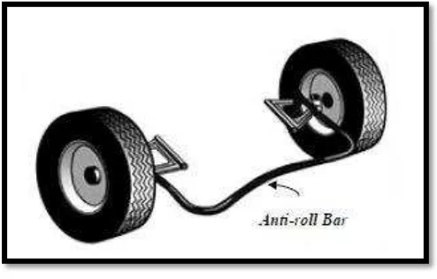
The anti-roll bar is a rod or tube that connects the right and left suspension
members. It can be used in front suspension, rear suspension or in both suspensions,
no matter the suspensions are rigid axle type or independent type. A typical anti-roll
bar is shown in Figure 2.1.
5
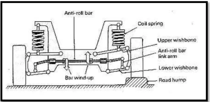
The ends of the anti-roll bar connect to the suspension links while the center
of the bar is connected to the frame of the car such that it is free to rotate. The ends
of the arms are attached to the suspension as close to the wheels as possible. If the
both ends of the bar move equally, the bar rotates in its bushing and provides no
torsion resistance. But it resists relative movement between the bar ends, such as
shown in Figure 2.2. The bar's torsion stiffness-or resistance to twist-determines its
ability to reduce such relative movement and it’s called as “roll stiffness”.
Figure 2.2 : An anti roll bar that attached to the suspension (The vehicle is crossing
over a road bump on one side). (www.reddit.com, 2005)
2.1.4 Anti Roll Bar Working Principles
The car begins to roll out of the corner when the car head into a corner. For
example, the car body rolls to the right when cornering to the left. The result,
anti-roll bar on the right side suspension are compressible. As the lower part of the
suspension moves upward relative to the car chassis, it transfers some of that
movement of the same component on the other side with a good anti-roll bar. In
effect, it tries to lift the left suspension component by the same amount. Because this
isn't physically possible, the left suspension effectively becomes a fixed point and the
anti-roll bar twists along its length because the other end is effectively anchored in
6
Nowadays, the expensive car is provided with active anti-roll technology.
These senses the roll of the car into a corner and deflate the relevant suspension leg
accordingly by pumping fluid in and out of the shock absorber. It is a high-tech,
super expensive version of the good old mechanical anti-roll bar. Body roll during
cornering can be reduced also by selection of the vertical suspension is more
difficult, but it will have a negative impact on the ride comfort. Stabilizer bars that
significantly contribute to an increase in motor vehicle comfort (Carlson, Catazarite,
and Clair, 2010).
2.1.5 Anti Roll Bar for Rollover Prevention
The main target of using anti-roll bar is to reduce the body roll. When a
vehicle deviates from straight-line motion, body roll occurs. The line connecting the
roll centers of front and rear suspensions forms the roll axis of a vehicle. Center of
gravity of a vehicle is normally above this roll axis. Thus, while cornering the
centrifugal force creates a roll moment about the roll axis, which is equal to the
product of centrifugal force with the distance between the roll axis and the center of
gravity. This moment causes the inner suspension to extend and the outer suspension
to compress, thus the body roll occurs as shown in Figure 2.3. Body roll also occurs
when a wheel crosses a bump on one side only, which was the case in Figure 2.2.
Figure 2.3 : A vehicle body roll during cornering (www.reddit.com, 2005)
Actually, body roll is an unwanted motion. The first reason for this is the fact
7
cornering. Therefore, the driver cannot drive the vehicle with confidence. The second
reason is its effect on the camber angle of the tires, which is the angle between the
central plane of symmetry of the wheel and the vertical plane at the center of the
contact patch. The purpose of camber angle is to align the wheel load with the point
of contact of the tire on the road surface. When the camber angle is changed due to
body roll, this alignment is lost and also the tire contact patch gets smaller. The
smaller the contact patch of the tire, the less traction exists against the road surface
(Comesky, J., 2002). Thus, body roll should be prevented.
The first way to prevent body roll is to eliminate its source, roll moment. By
increasing the roll center heights of the front and rear suspensions, this moment can
be reduced. But, this will cause considerable lateral wheel displacements during
bump and rebound with track variations during operation. Another negative effect is
the higher camber angle change. Another method for preventing excessive body roll
is to use stiffer suspension springs, thus making it harder for the suspensions to move
in opposite directions at the same time. This, however, reduces the ride comfort. A
compromise solution is to use softer suspension springs to provide ride comfort,
lower roll centers to avoid lateral wheel displacement and anti-roll bar to reduce
body roll.
Anti-roll bars serve two key functions. First, as explained above, they reduce
body roll, and second provide a way to redistribute cornering loads between the front
and rear wheels, which in turns, gives the capability of modifying handling
characteristics of the vehicle. By arranging the roll stiffnesses of the anti-roll bars at
the front and rear suspensions, it can be done. If a firmer anti-roll bar is installed at
the front, then the distribution of lateral load transmits increases toward the front
tires, since a firmer anti-roll bar allows less deflection, thus transfers lateral loads at a
faster rate. And the overall result is an additional understeer effect. Adversely,
increasing roll stiffness at the rear by using firmer anti-roll bar will create an
oversteer effect. Thus, anti-roll bars are also used to improve directional control and
stability.
One negative effect of anti-roll bars is that, too stiff bars can reduce the
adhesion on slick surfaces. This is especially true on snow and ice. They can also be