I/We admit that have read this report and in my opinion this report is enough in terms of scope and quality to bestowal
Bachelor of Mechanical Engineering (Automotive)
Signature : ………
Supervisor1 : ..………..
Date : ………
Signature : ………
Supervisor 2 : ..………..
i
THE DEVELOPMENT OF AN ACTIVE ROLL CONTROL FOR HEAVY VEHICLE
MOHD FIRDAUS BIN MOHD HUSSAIN
This thesis is submitted to the Faculty of Mechanical Engineering, in partial fulfillment of the partial requirement for the Bachelor of Mechanical Engineering (Automotive)
FACULTY OF MECHANICAL ENGINEERING UNIVERSITI TEKNIKAL MALAYSIA MELAKA
ii
“I declare that this report is my own work accept any summary or quotation that every single sources are explained”
Signature : ………...………
iii
To my beloved mother, father, brothers and sisters, All my sweet friends
All members of Bachelor of Mechanical Automotive (BMCA) My PSM supervisor, Mr. Mochamad Safarudin
iv
ACKNOWLEDGEMENT
First and foremost, I would to express my greatest gratitude and appreciation to my supervisor, Encik Mochamad Safarudin, who suggested and supervised this project. He also contributed lots of idea, experience, encouragement and energy as well. All the discussions that I have had with him have benefit to me for understanding lots about vehicle dynamics.
I also want to grateful to all my friends for their enthusiastically and generously sharing their knowledge and time for this project.
v
ABSTRACT
vi
ABSTRAK
viii
3.2.1 Roll dynamics system diagram 28 3.2.2 Lateral dynamics system diagram 29 3.2.3 Yaw dynamics system diagram 30 3.2.4 Tire normal force system diagram 31
3.2.5 Handling system diagram 32
ix
CHAPTER 4 RESULT AND DISCUSSION 37
4.1 Result and discussion 37
4.1.1 Roll angle graph 37
4.1.2 Body displacement graph 39
4.1.3 Actuator force 41
4.2 Validation 42
CHAPTER 5 CONCLUSION AND RECOMMENDATION 43
5.1 Conclusion 43
5.2 Recommendation 44
REFERENCE 45
x LIST OF TABLE
NO. TITLE PAGE
xi LIST OF FIGURES
NO TITLE PAGE
Figure 2.1 Equilibrium lateral acceleration in rollover of a rigid vehicle. 5
Figure 2.2 Roll response to a step input. 6
Figure 2.3 Model of the modified trailer suspension, showing the
location of the actuators and the anti roll bar 7 Figure 2.4 Force distribute by spring, damper and actuator 8
Figure 2.5 Layout of pneumatic drive 9
Figure 2.6 Layout of hydraulic drive 9
Figure 2.7 Block diagram of the local controller system. 11 Figure 2.8 Lateral and longitudinal force 12
Figure 2.9 Force analysis of a simple vehicle in cornering 14 Figure 2.10 Free body diagram of small medium heavy vehicle 15
Figure 2.11 MATLAB Simulink 22
Figure 3.1 Project flow chart 23
Figure 3.2 Simulink system full car model 26
Figure 3.3 Load and force distribution 27
Figure 3.4 Roll dynamic Simulink system 28
Figure 3.5 Lateral dynamic Simulink system 29
Figure 3.6 Yaw dynamic Simulink system 30
Figure 3.7 Tire normal force Simulink system 31
Figure 3.8 Vehicle handling Simulink system 32
Figure 3.9 Simulink library browser 34
xii
Figure 4.1 (a) Roll angle versus time without controller 38 Figure 4.1 (b) Roll angle versus time with controller 39 Figure 4.2 (a) Body displacement versus time without controller 40 Figure 4.2 (b) Body displacement versus time with controller 40 Figure 4.3 Comparison between the systems with controller and without
xiii
a distance of centre of gravity from front axle (m) b distance of centre of gravity from rear axle (m)
c/t track width (m)
h c.g. height (m)
hrcf front roll center distance below sprung mass centre of gravity (m) hrcr rear roll center distance below sprung mass centre of gravity (m)
Jx roll inertia (kg m2)
Jy pitch inertia (kg m2)
Jz yaw inertia (kg m2)
M vehicle sprung mass (kg)
u/v/w longitudinal/lateral/vertical velocities of centre of gravity in body-fixed coordinate (m/s)
θ pitch angle (rad)
φ roll angle (rad)
yaw angle (rad)
xiv Fxt/Fyt/Fzt tire longitudinal/lateral/vertical forces (N)
Fxg/Fyg/Fzg longitudinal/lateral/vertical forces at tire contact patch in coordinate frame (N)
Fxgs/Fygs/Fzgs longitudinal/lateral/vertical forces at tire contact patch (N) Fxs/Fys/Fzs longitudinal/lateral/vertical forces transferred to body (N) Jw rotational inertia of each wheel (kg m2)
mu unsprung mass (kg)
r tire radius (m)
s tire longitudinal slip
α tire lateral slip (rad)
angular velocity of wheel rotation (rad/s)
xv
LIST OF APPENDIX
APPENDIC PAGE
1
CHAPTER 1
INTRODUCTION
This chapter will provide the information about overview of the research conducted for this thesis. First, the overviews about active roll control system for heavy vehicle, then the equations and methods for active roll system will be presented.
Rollover for heavy vehicle
Heavy vehicles are commercially used to transport goods and are due to strong competition operated by very cost sensitive owners. Small medium heavy trucks are bought by customers with the purpose of being as profitable as possible, in other words to transport as large amount of goods as fast and cheap as possible. New technology is
2
forces arising from curb impacts, soft ground, or other obstructions that may “trip” the
vehicle.
The rollover of heavy vehicles is an important road safety problem in the worldwide. Several studies have been reported from US National Highway Traffic Safety Administration that the serious heavy vehicle accidents involve rollover. The review of heavy vehicle safety considers that while some rollover accidents to articulated vehicles were unnecessary given a complicated warning system and highly skilled driver, the majority could not only be avoided by the involvement of advanced active systems. It is very difficult for truck drivers to observe their proximity to rollover while driving.
3
1.2 Problem Statement
Three major causes of rollover have been identified. The first problem contributing factors of rollover is sudden course deviation which is combination between heavy braking and high initial speed. The other factors are excessive speed on speed and shifting load.
Therefore, this report will design and implement of an active roll control system for a heavy vehicle. A simple yaw roll model of small medium heavy vehicle is developed, validated and used for control design.
1.3 Objective
The objective of this project is design active roll control system to prevent roll over of heavy vehicle and also to provide the vehicle with an ability to resist overturning moments generated during cornering and speeding.
1.4 Scope
4
CHAPTER 2
LITERATURE REVIEW
In the development of active roll control systems, a vehicle model that can represent realistic roll behavior is essential to predict impending rollover as well as accurately applying the actuation force to avoid vehicle rollover.
2.1 Roll stability
Roll stability refers to the ability of a vehicle to resist overturning moments generated during cornering and speeding, that is, to avoid rollover. Roll stability is determined by the height of the center of mass, the track width and the kinematic and properties of suspension.
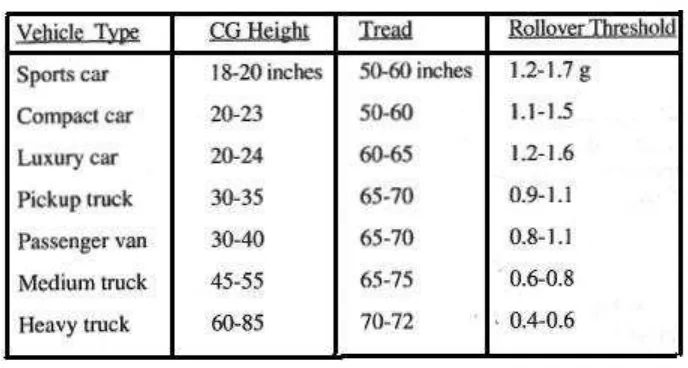
5 The rollover threshold differs particularly among the various types of vehicles on the road. As examples, typical values fall in the following ranges
Table 1: Rollover Threshold for Road Vehicle (Source: Thomas D. Gillespie, 1992)
The connection between lateral acceleration and roll angle can be derived by the overload lateral acceleration produces a roll acceleration that further increases the angle driving away from the equilibrium point. In order to be in equilibrium, the vehicle roll angle must be at the precise value on the above curve where the equilibrium lateral acceleration matches the actual as shown in chart below.
6
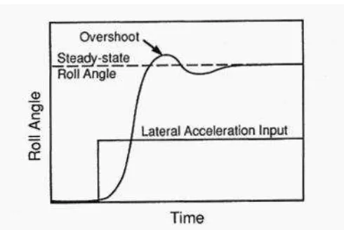
The roll angle can overshoot means that wheel lift-off may occur at lower levels of lateral acceleration input in transient maneuvers. A step steer maneuver that produces a lateral acceleration level just below the static threshold can result in rollover in the transient case because of the overshoot. Thus the roll angle versus time results should be like the graph below.
Figure 2.2: Roll response to a step input. (Source: Thomas D. Gillespie, 1992)
7
2.2 Anti roll bar
The active roll control system consists of a stiff U-shaped anti-roll bar, connected at each end to the trailing arms, and two hydraulic actuators located between the chassis and anti-roll bar (Figure 2.3). The actuators apply equal and opposite vertical loads to the bar, thereby twisting it, and applying a roll moment to the vehicle body. The result is a floating anti-roll bar whose position is determined by the wheel positions and the actuator positions. Use of a single hydraulic actuator would have been considerably simpler, but was not possible because the much larger stroke requirement exceeded the available space under the vehicle.
Figure 2.3: Model of the modified trailer suspension, showing the location of the
8
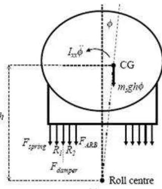
The worst case transient force is that required to drive the sprung mass sinusoidal at a given frequency with the maximum amplitude of roll angle. Figure 2.4 shows the forces acting on the body in the dynamic case. There are forces from the springs (Fspring), the dampers (Fdamper) and the actuators (FARB).