UNIVERSITI TEKNIKAL MALAYSIA MELAKA
EFFECT OF CUTTING PARAMETERS IN MILLING
TITANIUM ALLOY TI-6AL-4V USING PVD CARBIDE
INSERT
This report submitted in accordance with requirement of the Universiti Teknikal Malaysia Melaka (UTeM) for the Bachelor Degree of Manufacturing Engineering
(Manufacturing Process) (Hons.)
By
HADI AFIQ BIN MOHAMMAD TAHIR
B051210112
911201105587
UNIVERSITI TEKNIKAL MALAYSIA MELAKA
BORANG PENGESAHAN STATUS LAPORAN PROJEK SARJANA MUDA
TAJUK: EFFECT OF CUTTING PARAMETERS IN MILLING TITANIUM ALLOY TI-6AL-4V USING PVD CARBIDE INSERT
SESI PENGAJIAN: 2014/15 Semester 2
Saya HADI AFIQ BIN MOHAMMAD TAHIR
mengaku membenarkan Laporan PSM ini disimpan di Perpustakaan Universiti Teknikal Malaysia Melaka (UTeM) dengan syarat-syarat kegunaan seperti berikut:
1. Laporan PSM adalah hak milik Universiti Teknikal Malaysia Melaka dan penulis. 2. Perpustakaan Universiti Teknikal Malaysia Melaka dibenarkan membuat salinan
untuk tujuan pengajian sahaja dengan izin penulis.
DECLARATION
I hereby, declared this report entitled “Effect of Cutting Parameter in Milling Titanium Alloy Ti-6Al-4V Using PVD Carbide Insert” is the results of my own research except as cited in references.
Signature : ………....
Author’s Name : HADI AFIQ BIN MOHAMMAD TAHIR
APPROVAL
This report is submitted to the Faculty of Manufacturing Engineering of UTeM as a partial fulfillment of the requirements for the degree of Bachelor of Manufacturing Engineering (Manufacturing Process) (Hons.). The member of the supervisory is as follow:
……… (Dr. Mohd Sanusi bin Abdul Aziz)
i
ABSTRAK
ii
ABSTRACT
iii
DEDICATION
iv
v
2.7.7 Surface Roughness Measurement Instruments 16
CHAPTER 3: METHODOLOGY 17
3.1 Experimental Equipment 19
3.1.1 CNC Milling Machine 19
3.1.2 Workpiece 21
3.1.3 PVD Carbide Insert and Tool Holder 22
3.1.4 Stereo Microscope 23
3.1.5 Surface Roughness Tester 24
3.2 Planning of the Cutting Parameter 25
3.3 Conducted the Experiment 28
3.4 Experimental Procedure 30
CHAPTER 4: RESULT AND DISCUSSION 31
4.1 Tool Wear Progression 31
4.2 Surface Roughness Evaluation 39
4.3 Effect of Cutting Parameter on Tool Life and Surface Roughness 41 4.3.1 Effect of Cutting Speed on Wear Rate and Surface Roughness 41 4.3.2 Effect of Feed Rate on Wear Rate and Surface Roughness 44 4.3.3 Effect of Depth of Cut on Wear Rate and Surface Roughness 47
CHAPTER 5: CONCLUSION & FUTURE WORK 49
5.1 Conclusion 49
5.2 Recommendation 50
vi
LIST OF TABLES
3.1 The specification of the VARIAXIS 630-5X II T 20
3.2 The composition (wt%) of Ti-6Al-4V 21
3.3 Mechanical properties of Titanium 21
3.4 Dimensional geometry of the insert 22
3.5 Range of machining parameters 26
3.6 Effective diameter for each depth of cut 27 3.7 List of experiment based on research gap 27 3.8 List of experiment based on research gap 27
3.9 CNC Coding 29
4.1 Results of total no of run and machining time for each experiment 32 4.2 Result of tool wear by time with titanium alloy Ti-6Al-4V 33
4.3 Results of the Wear Rate 38
4.4 Minimum, maximum and average value of surface roughness for each experiment
39
4.5 The results of average surface roughness 40 4.6 List of experiments with different cutting speed, constant feed
rate and depth of cut
41
4.7 List of experiments with different feed rate, constant cutting speed and depth of cut
44
4.8 List of experiments with different depth of cut, constant cutting speed and feed rate
47
vii
LIST OF FIGURES
2.1 The schematic diagram of PVD process 10
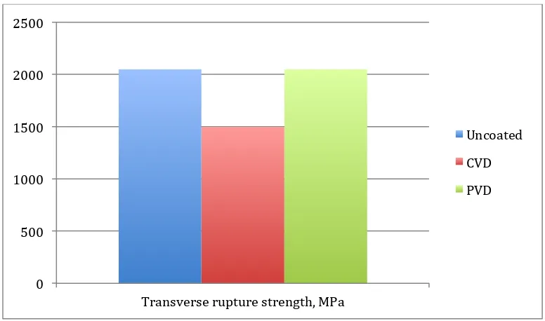
2.2 Comparison of the transverse rupture strength of uncoated and coated carbide tools. Measured by a three-point bend test on 5 x 5 x 19 mm specimens of 73WC-19C-8Co
11
3.1 Flow chart for the methodology 18
3.2 The Mazak VARIAXIS 630-5X II T 19
3.3 The carbide insert of cutting tool 22
3.4 The schematic of round insert cutting tool with tool holder 23
3.5 Tool holder Sumitomo WRC10020EM 201 23
3.6 Meiji Techno EMZ – 13TR Stereo Microscope 24 3.7 Portable Surface Roughness Tester Mitutoyo SJ 301 24 3.8 The relationship between the factors and responses 25
4.1 Overall views of tool wear progression 34 4.2 Wear pattern at beginning of machining 35
4.3 Wear pattern at middle of machining 35
4.4 Wear pattern at end of machining 36
4.5 View of tool progression until 74 min of machining 37
4.6 Wear Rate for each experiment 38
4.7 The minimum-maximum graph of surface roughness for every experiment
39
4.8 Average surface roughness for Exp 1 40
4.9 Effect of cutting speed on wear rate 42
4.10 Effect of cutting speed on surface roughness 43
4.11 Effect of feed rate on wear rate 45
4.12 Effect of feed rate on surface roughness 46
4.13 Effect of depth of cut on wear rate 47
1
1.1 Background
The development of new alloys and engineered material produces higher strength and stiffness properties. Technologies of machining have been enhanced in order to achieve better quality for machining high strength and toughness materials. These types of materials are commonly used in making automotive and aerospace components. Nowadays, the capabilities of machine and cutting tools allow the manufacturer to machining hardened steels. However, in order to gain the most optimized results, there are several of factors need to be considered such as types of cutting tools, type of machine and cutting parameters. Coated cutting tools are established for refining performance in machining and also to lesser the effort of machining hard materials. Coated cutting tools can increase tool life up to ten times longer than uncoated cutting tools, which allowing for high cutting speed (Kalpalkjian and Schmid, 2006). This will decrease machining time and also reduce production cost.
2
1.2 Problem Statement
One of the major concern in manufacturing environments is the tool life durations, which also affecting the economics of operations. Milling operation can be used for machining ferrous and non-ferrous materials.
The selection of good cutting tool is one of the most critical factors to be considered before machining operation. Appropriate cutting tool will contribute to longer tool life performance and better surface finish for the machined parts. However, good cutting tools that possess good mechanical properties are high cost. The need of good cutting tools is a must for machining hard materials. As an alternative, coated carbide insert can be used as it’s possess good mechanical properties and capable to do high speed machining. The cost of coated carbide inserts is lower than high end cutting tool materials. Coated carbide insert has been widely used due to its good mechanical properties and low cost.
In machining, cutting parameters must be considered as it is one of the most influenced factor that affecting the outcome of the machining. A good machining result depends on the types of materials, types of cutting tool and cutting parameters. This research was conducted to identify and compare the wear rate of the PVD coated carbide tool and the surface roughness of the machined titanium using CNC milling machined.
1.3 Objectives
The fundamental objectives of this research are:
i. To study the tool wear progression and surface roughness when machining titanium alloy Ti-6Al-4V using PVD Carbide Insert
3
1.4 Scope
The scopes of this research are:
i. This research will be focus on CNC milling operates under dry conditions ii. The carbide insert is coated by using physical vapor deposition (PVD) iii. The form of the selected carbide insert is round, which is 10mm diameter iv. The workpiece for this research is titanium alloy Ti-6Al-4V
v. The measurement of tool wear is measure using Stereo Microscope
vi. The measurement of surface roughness is measure using Portable Surface Roughness Tester
1.5 Outline of the Project
This research contains 5 chapters which containing PSM 1 and PSM 2. PSM 1 consists 3 chapters, which includes introduction, literature review and methodology. PSM 2 consists 2 chapters, which includes result and discussion of this experiment and conclusion. The chapter 1 is generally about the overview of the project, problem statement related to industry issues, objectives, scope of the project and the important of the study.
Chapter 2 is the literature review based on the references collected from journal papers, books and website. This chapter discussed about the information about this specific research area. It also discuss concisely about milling machine and operations, cutting tools and about previous and recent research that have significant relationships with this research.
4 Next, chapter 4 contains result and discussion, which the data that collected from the experiment is analyzed and discussed.
5 The literature review is a simple summary of the sources where the knowledge, information or ideas of the author in a particular subject area which is established and defined. The discussion on the problem issue, research objectives and the methodology used are supported by the established knowledge that reviewed from the books, journals and articles. This chapter provides detailed explanation on titanium, cutting parameters, coated cutting tools, machining performances and surface roughness.
2.1 Titanium
Titanium is a material that is strong and light metal. Titanium has the element symbol of Ti, originates from the Greek called Titans. Metallic titanium usually used to build structural parts for planes and their mechanisms. Atoms occurred in everything around you. Atoms contain tinier particles, which is protons, neutrons and electrons. Both of the neutrons and protons are found in the nucleus, which located at the center of each atom. The electrons rotate around the nucleus in a multiple of layers called electron shells. Titanium has 22 atomic numbers due to 22 positively charged protons in the nucleus. Neutrons are about the similar size as protons but have no electrical charge. So, the atomic mass of the titanium is 48. Then number of electron for titanium is similar to the number of proton, which makes the amount of electrons are 22.
6 makes it as an ideal material for the creation of high-speed airplane and astronomical vehicles. Titanium is very strong, lightweight and can resist tremendously high temperatures. Matthew (2000) stated that the density of titanium is approximately 60% of the steel or nickel-base super alloys. The tensile strength of titanium alloy can be compare with lower strength martensitic stainless and better than austenitic or ferritic stainless alloy. The marketable alloys of titanium are beneficial at temperatures approximately 538° to 595°C depends on composition. However, there are several alloy structures may have useful strengths exceeding this temperatures. Ballester (2000) stated that the price of titanium is approximately 4 times greater than stainless steel. Titanium has exceptional corrosion resistance, surpasses the resistance of stainless steel in most circumstances. Titanium also may be forged, cast able and processed by standard techniques. It can be processed by powder metallurgy. Moreover, Matthew (2000) also stated that titanium can be joined together by fusion welding, adhesives, brazing and fasteners.
2.2 Cutting parameters
7 2.2.1 Tool life and cutting speed
The cutting tools for machining titanium alloys are sensitive to changes in feed. The tool life is very short when at high cutting speed. However, as the cutting speeds reduce, tool life considerably increases.
2.2.2 Cutting Tool Materials
The characteristic of cutting tool that required to machining titanium is abrasion resistance and suitable hot hardness. Examples of materials that usually used for machining titanium are ceramics, coated carbide and polycrystalline diamonds. The cutting tools should be maintains sharp as wear tools causes poor surface finish and tearing.
2.2.3 Cutting Fluids
Coolant can extremely extend the cutting tool life. Coolant allows heats to transfer efficiently and decrease cutting forces among the tool and work piece. This cutting fluid doesn’t cause any degradation of the properties of the work piece. Cutting fluids help to transfer the heat and it also washes away chips and reduces cutting forces.
2.2.4 Machining Speeds and Feeds
8
2.3 Coated Cutting Tools
Metal cutting industry undergoes one of the most revolutionary changes over the last 30 years in with the development of thin-film hard coatings and thermal diffusion processes. These developments brought significant advantages to users or machining industry and also increasing applications. Nowadays, most of the cutting tool in which 50% of high speed steel (HSS), 85% of carbide and 40% of super-hard tools used in industry is coated. Titanium aluminum nitrate (TiAIN), titanium carbonitrade (TiCN), solid lubricant coatings and multilayer coatings are the most common coating for substrate such as carbides. Coating increases tool life productivity and performance in cutting tool. It makes high speed and high feed cutting in dry machining or when machining of difficulty to machine materials (Astakhovand and Davim, n.d.).
Functional properties of tools are determined by the stresses that occur in hard coatings deposited on the edge of the cutting tools. Almost all-vacuum metallic and non-metallic deposited coating undergoes stress. Stress on the coating are determined by critical factor of the coating material and base material, which are coating structure, the relationship between deposition temperature and melting point of the coated material, temperature in which this coating is exploited and method of deposition. Functional properties of coated cutting tools also depend on the thermal internal stresses that can leads to crucial stress. Substrate that has bigger thermal expansion coefficient than the material of the coating material causing compressive stress in the coating is more favorable. Compressive stresses in the coating prevent production of cracks. (Dobrzanski et al. 2009).
9 cutting and cutting with or without coolant can be performing using coated carbide tool. (Lughscheider, 2003).
2.4 Coated Carbide Tools
10
2.5 Physical Vapor Deposition (PVD)
Chemical vapor deposition (CVD) and physical vapor deposition (PVD) are the main processes used to add coating material to cutting tools where the substrates are high speed steel (HSS) cemented carbide, ceramic or a super hard material. (Destefani, 2002). Physical vapor deposition (PVD) was developed in the 1980 as a viable process for applying hard coatings to cemented carbides tools. The coating is deposited in a vacuum. Evaporation or sputtering produce metal species of the coating then react with a gaseous species such as nitrogen or ammonia in the chamber and deposited onto the substrate. Physical vapour deposition (PVD) is one of the hard coating processes that have the ability to reduce tool wear of high speed steel (HSS) and carbide metal cutting tools. The service lifetime of cemented carbide tools coated with titanium carbide (TiC) and titanium nitride (TiN) increase by a factor of ten compare to uncoated tools (Watmon et al. 2010). Mehrota and Quinto (1985) stated that composition, microstructure and mechanical properties of the coating material and substrate are important to increase performance of coated tools. Figure 1.1 shows the schematic diagram of PVD process.
Figure 2.1: The schematic diagram of PVD process
11
2.6 Comparison between PVD and CVD
The PVD coating process is executed at lower temperatures which approximately 500°C. The PVD coating process has a line-of-sight disadvantage. On the other hand, CVD coating required high deposition temperature which approximately 1000°C. These will lead the coating to degrade the strength of the cemented carbide substrate. Figure 1.2 shows comparison chart of the transverse rupture strength of uncoated and coated carbide tools.
Figure 2.2: Comparison of the transverse rupture strength of uncoated and coated carbide tools. Measured by a three-point bend test on 5 x 5 x 19 mm specimens of 73WC-19C-8Co (Joseph, 1995)
CVD layers provide excellent adhesion and wear resistance and the PVD layer offers a hard, fine-grain, crack-free, smooth surface capable with compressive residual stress. However, amorphous PVD Al2O3 coatings are unstable and are not as pleasant
as the crystalline Al2O3 attained in CVD. PVD TiAlN coatings are also chemically
12 2.6.1 Microstructure
PVD process possesses finer grain sizes and better compressive residual stress. Compressive residual stress grown during ion bombardment in definite PVD processes retards crack propagation and thus creates a fracture toughness benefits for PVD-coated tools.
2.6.2 Adhesion
Good performance of the coated tools depends on how superior the coating adhesions to the substrate are. Coating phase transformations can also induce stresses that may affect adhesion. Substrates surface impurities due to coating, especially in the PVD process, can have unfavorable effects on coating adhesion and should be reduced. Current PVD technology offers well-adhering coatings that are as efficient as CVD coatings in demanding applications.
2.6.3 Coating Thickness
The coating thickness needs to be optimized to achieve maximum metal cutting productivity. If the coating thickness is too thin, the effect persists for a negligibly short time during cutting. If the modified tool surface is too thick, the layer will act as a bulk material and the benefit of an engineered composite may be lost. Working tool coatings should be 2 to 20µm thick. Coatings deposited by CVD are normally 10µm thick, while PVD coatings are typically less than 5µm thick.
2.7 Machining Performances
13 the machinability of material, which are the properties of the work piece and the machining conditions.
The machining conditions that affect the machining performances are:
i. Tool life
ii. Surface roughness iii. Cutting force
iv. Material removal rate
The material properties that affect the machining performances are:
i. Shear strength
ii. Strain hardenability, the growth in strength and stiffness with increasing plastic deformation
iii. Hardness, the properties of material to prevent indentation
iv. Coefficient of friction, which leads to various reaction between the cutting tool and chips
v. Thermal conductivity
2.7.1 Tool Life