ISSN: 1693-6930
accredited by DGHE (DIKTI), Decree No: 51/Dikti/Kep/2010 445
Automated
Navigation System based on Weapon-Target
Assignment
Gayuh Titis Permana1, Maman Abdurohman1, Mohammad Khairudin2, Mohammad Lutfi1
1
Facultyof Informatics, Telkom Institute of Technology Jl. Telekominikasi no.1 – Dayeuhkolot – 40257 tlp/fax 022-7565931
e-mail: [email protected], [email protected]
Pengoperasian senapan pada tank masih digerakkan secara manual. Kondisi ini tidak ideal untuk operasi yang berbahaya. Diperlukan sistem pengendali otomatis untuk mengoperasikan senjata dengan tetap mempertahankan ketepatan target sasaran. Pada paper ini telah dirancang suatu sistem pengendalian senjata otomatis berbasis citra digital. Beberapa metode pengolahan citra digital digunakan untuk meningkatkan ketelitian arah senapan sehingga mendapatkan target yang dituju. Metode yang digunakan dalam pengolahan citra digital adalah penjejakan pergerakan Camshift. Metode ini dibandingkan dengan metode penjejakan pergerakan Lucas Canade. Perbandingan ini dilakukan untuk mendapatkan hasil yang lebih presisi diantara kedua metode tersebut. Hasil pengolahan citra digital ini digunakan untuk mengendalikan arah senapan sehingga menuju pada sasaran yang diinginkan. Hasil pengujian penelitian menunjukkan bahwa implementasi penjejakan pergerakan dengan metode Lucas Kanade pada alat simulasi tembak telah berhasil. Kinerja metode penjejakan pergerakan Lucas Canade lebih baik dibandingkan dengan metode Camshift. Penggunaan metode Lucas Canade untuk pengendalian senapan tank lebih baik dan telah memenuhi kebutuhan.
Kata kunci: Camshift, Lucas Canade, pengolahan citra, penjejakan pergerakan, senapan
Abstract
Operating of weapon on the tank is mostly by manually. It is not desired performance for a critical operation. An automatic control system is required to operate the weapon with the target while maintaining the accuracy. In this paper has designed an automatic weapon control system using object image proccessing. Various an image processing methods used to improve the weapon accuracy to obtain the intended target. The method used in digital image processing is the Camshift motion tracking method. This method is compared with the Lucas Canade motion tracking method. This comparison is conducted to found more precise results between the two methods. Results of object image processing are used to control the direction of the weapon that towards the desired goal. The results show that the implementation of the Lucas Canade motion tracking method using fire simulation tools have been successful. The performance of the Lucas Canade motion tracking methods is better than the CamShift method. Using Lucas Canade method for weapon controller is accordance with the purposes.
Keywords: Camshift, image processing, Lucas Canade, motion tracking, weapon
1. Introduction
the tank weapon was operated manually by humans. One of its advantage is the gun can be moved freely in accordance of the human and its disadvantage is operator saveless.
A previous research on modeling and algorithm of weapon target assignment (WTA) is conducted by Cai [1]. Several methods are used for solving WTA problem. Solving WTA problem by combining of ant colony optimization and the ability to cooperatively explore the search space and to avoid convergence have conducted by [2] and [3].
Wacholder [4] presented a neural network-based optimization algorithm for the static weapon-target assignment problem. A desired weapon profiles can be obtained by applying digital image proccessing for automaticity of the directed weapon. The camera can be used as sensors to identify objects that can replace the role of the humans sensing. The object that was captured by a camera sensor can be processed using image processing techniques [5], [6]. Motion tracking method such as Camshift and Lucas Kanade algorthms can be used for image processing.
Continuously Adaptive Mean Shift (Camshift) algorithm is an advance development of basic algorithm MeanShift performed repeatedly in order to search for a local probability density function (PDF) that approximates the empirical PDF [7]. While Lucas Kanade method is one of the Motion Tracking algorithms that perform searches based on color. The objectives of this paper are designing and implementing automatic rifle activator system in following a moving target using motion tracking with CamShift and Lucas Kanade method. Analyzing the performance of the system in capturing and following a moving target with a variety of objects, object size, speed and distance of objects moving objects on the camera and measure the response time since the determination of the target until the object is locked.
2. Research Method 2.1 Digital Image
Digital image is an image f (x, y) that has spatial coordinates, and the discrete levels of brightness. The image is light which is reflected from an object. The f (x, y) function can be viewed as a function with two elements. The first element is the power source of light that surrounds our view of the object (illumination). The second element is the amount of light reflected by objects into our eyes (reflectance components). Both were written as a function of i (x, y) and r (x, y) which are incorporated as a multiplication function to form the function f (x, y):
F(x,y) = i(x,y) * r(x,y) Where 0<i(x,y) <∞ and 0<r(x,y)<1 (1)
Digital image is a matrix consisting of rows and columns, where each row and column index pair claimed a point in the image. The value matrix is expressed brightness values that point. The points are referred to as image elements, or pixels (picture elements).
2.2 RGB and HSV color model
RGB color model is a color model based on the concept of a strong increase primary light is Red, Green and Blue. Model HSV shows the color space in the form of three main components, Hue, Saturation and Value. A hue is the angle from 0 to 360 degrees. Usually 0 is red, 60 degrees is yellow, green is 120 degrees, 180 degrees is cyan, 240 degrees is 300 degrees is blue and magenta. A hue indicates the color type (such as red, blue or yellow) or shades of color, where color was found in the color spectrum. Red, yellow and purple (purple) are words that indicate hue. Saturation of a color is a measure of how much the purity of color.
2.3 Lucas Kanade
Optical flow is defined as a visible movement due to the image brightness (dark light image). Suppose I (x, y, t) is the image brightness varies with time as an illustration of a sequence of several images (image sequences). There are two assumptions: Brightness I (x, y, t) depends on x, y coordinates contained in a larger part of the image and brightness of each point of an object moving object does not change with time.
potentially moving with a speed that is very different. As for the components of resilience or robustness is related to sensitivity of tracking to the respect of any change to the light, the size of the image movement, in particular, in order to handle large movements, the better we choose to use a large integration window. By using optical flow equation for a group of pixels and assume that the pixels have the same speed, it will facilitate the process of computing to solve a linear equation.
2.4 CamShift
Continuously Adaptive Mean Shift (ChamShift) is the advance of Mean Shift algorithm. MeanShift algorithm essentially operates with finding an average (mean) of the function of solid opportunities a distribution of the image in the domain of x, y [8], [9]. For example, we assume a distribution f, Euclidean contains distribution of stage algorithms Mean Shift in Euclidean distribution is as follows: (1). The size of the predefined search window. (2). Initial search window locations that have been determined. (3). Calculate the mean area in the search window. (4). Position the search window to the middle of the mean as calculated in step (3). (5). Repeat step (3) and (4) until convergence (or until a shift in the mean area is less than the threshold/limit specified).
CamShift algorithm is a development of the basic algorithm MeanShift performed repeatedly in order to detect movement of objects from video imagery. MeanShift operates based on the probability distribution of the image. To detect color images on a video, then the color image should be represented in the form of probability distribution image with the help of image histogram. Color distribution of the video is always changing every time, then the algorithm MeanShift must be developed to be used to track objects on every frame.
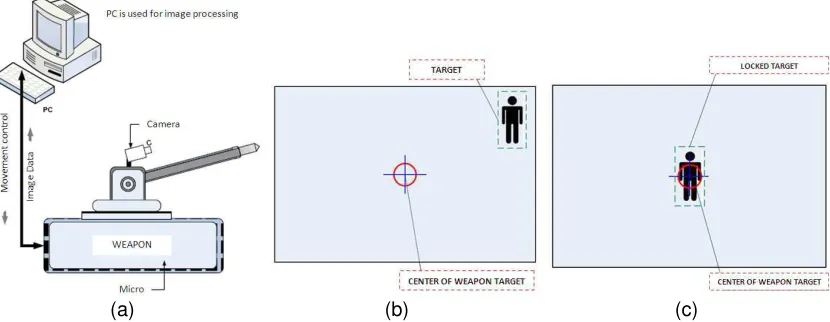
(a) (b) (c)
Figure 1. (a) Block Diagram System (b) initialisation of target (c) process to lock the target.
3. Result and Discussion 3.1 System analysis
System requirements consist of two parts, software and hardware. The hardware used to build this application consists of PC: Intel Core 2 Duo T5450, 1.66 GHz, HD 100 GB, 1.5 GB DDR RAM, VGA Card 256 MB, Keyboard and Mouse, Fusil: Logitech QuickCam S5500, Microcontroller ATMega 8535, Motor Driver, Motor DC 12 V. DB25 connector (male, female) data cable and Construction fusil (wooden boards, bearings, axles). Software is used to build application are Operating System Windows XP Home, Microsoft Visual Studio 2008, Intel open source Computer Vision Library.
center of the screen coordinates. From the information obtained from tracking the object, would produce a control that will move the rifle for tracking object is at the specified coordinates.
3.2 System Design
Overview of functionality and interaction between the user's systems with the system are modeled in a Use Case Diagram. Based on Use Case Diagram on Figure 2. The system has three main action namely: tracking target, setting camera and setting control.
Figure 2. System Using a Case Diagram
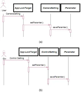
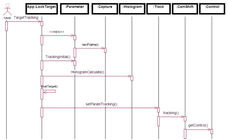
Sequence diagram shows how a process run in the system. Figures 3 and 4 show the sequence diagram of tracking target.
(a)
(b)
Figure 4. Sequence Diagram of tacking target
4. Implementation and System Testing
Implementation of the system carried out in two different environments, a PC and a microcontroller-based hardware in the form of fire simulation tool. Input video image is taken from a sensor, camera.
4.1 Experiment scenarios
Scenario I: testing the accuracy and speed of the system in a stationary track objects. Tests carried out repeated 10 times, with variations of objects, distance and location. Tests conducted by putting some paper that has a different color difference to be used as a target.
Scenario II test the accuracy and speed of the system in tracking a moving object (Rifle and objects are both moving). Tests carried out repeated 10 times, with different variations of the object color, speed and direction of movement of the target. By direction of the rotating target, move up, down, right, left and moved irregularly. The variation of speed is done by beginning the movement slowly and then fast and slows again.
Secenario III is used to determine the maximum speed of movement of the target can still be captured by the system. Testing is done by conditioning the camera sensor is at rest, then take the target of repeated with increasing speed. The speed that can’t be captured by the system that became the maximum capability in capturing the target system based on its speed.
Table 1. Testing result of Scenario 1 with Lucas Kanade
No Frame number
Target coordinat
Dist
(pxl) Time(s)
Speed (Frame /sec) Init X Init Y Curr X Curr Y
1 22 80 80 160 121 89.44 3.407 6.46 2 35 46 184 161 115 130.74 4.828 7.25 3 51 258 73 161 118 108.69 7.36 6.93 4 49 249 45 162 120 253.78 4.172 11.74 5 67 8 163 155 115 157.97 4.86 13.79 6 22 176 47 164 118 177.37 1.906 11.54 7 33 272 211 161 121 144.31 4.516 7.31 8 46 58 161 159 123 74.03 7.125 6.46 9 47 294 185 163 122 148.93 5.578 8.43 10 41 220 191 165 120 223.79 2.625 15.62
4.2. Analysis of Testing Result
The results and test analysis after several testing, the results of the testing system is divided in 3 (three) sekenario is as follows: Table 1 presents the result and test analysis secenario using the speed of motion I motor vertical and horizontal with the speed constant temperatures, i.e. with 5π rad/second.
First test shows the location of the target in pixel coordinates is at the point (80.80) with a distance of 89.44 pixels from the center point of the target. In the first test target can be locked in a time of 3.407 seconds by taking 22 frames.
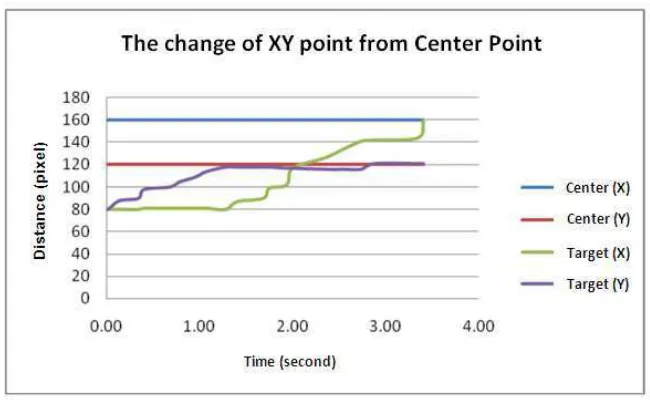
Otherwise the target end point is locked at the point (x, y pixels) (160.121). Figure 5 shows the target movement towards the center point.
The figure 5 shows the change in the center of the target per unit time. Where X and Y values will change with the movement fusil down then move to the left. Figure of fusil movement towards the target are presented in Figure 5.
Figure 5. Changes to the xy from center point per unit time.
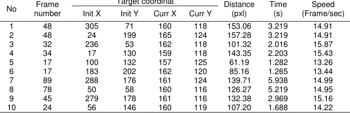
The testing results of the system in scenario I of stationary targets with movement controls the direction (right, left, up, down) get a better accuracy. Proven at every lock the target on a different location always finds the correct result (the final coordinates of the target is in the tolerance of the center point shot). Test results with two-way control can be shown in Table 2.
On the other hand, the test result the scenario I under control of the direction and control of two-way towards the target in a stationary condition is proven to lock the target well. Control two-way give a more subtle movement of the control using one-way. Change the value of dx (x target - x center) with value change(target y - y center) is not always walk in balance. If the value of dx> dy dy will be faster toward the central y value. This is because vertical movement fusil (y) and horizontal (x) has the same speed, so if dx and dy have different values will result in the achievement of targets against xy xy center requires a different time.
Table 2. Test results Scenario 1 Analysis and control of two-way Lucas Kanade
No Frame
Table 3. The results of second scenario with Lucas Kanade method
No Number Frame Target coordinat Time (s) Movement
Test Results and Analysis scenario scenario II Testing conducted on a dynamic target. From the results obtained on the testing there are several conditions at the time of locking the target. Fusil speed used was 5 cm/sec.
In the test scenario II - 1 test results indicate that there is a process lock as much as 18 times in 27.39 seconds, and 18 times in a state tracking. The condition was caused of the movement and speed of the target does not regular to allow the status of the target which is already in locked state and then add a speed that exceeds the velocity of fusil, giving rise to the distance between the center of the target which can change its state to a tracking. Table 3 shows the results of second scenario with lucas kanade method.
In test II - 6, the results are obtained from these tests that the initial velocity (below 5 cm/sec) target can be locked properly, after a speed is more than 5 cm/sec, the target changed to tracking the status of the target. This is due to the limited speed of motion of gunshot tool. Table 4 shows the results of second scenario with Camshift method.
On scenario II found ambiguity in detecting of the target system. It is found when the target has the same color as the color of objects that are on adjacent coordinates. From the data obtained during tracking a target that has a color (R = 182 | G = 169 | B = 180) moving through the objects that have the same color in RGB (R = 182 | G = 169 | B = 180). The system can still find the object that is considered a target by matching the color characteristics.
Table 4. Test results Scenario 2 with the method CamShift
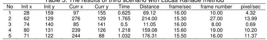
Table 5. The results of third scenario with Lucas Kanade method
No Init x Init y Curr x Curr y Time Distance frame/sec frame number pixel/sec
The objective of the third testing scenario is to get the maximum speed limit of moving objects that can still be tracked by the system. Based on the data obtained from the experiment a maximum speed of movement of the system is 11.37 pixels/sec.
5. Conclusion
Based on the anlysis of the result we conclude that Image-based motion tracking controller can be used as a rifle in the direction of motion do locking the target. The velocity gunshot effect the success of locking the target. Fusil velocity with the speed of image processing on the PC must be balanced. Response time specification using by Lucas Kanade method is faster than using CamShift, due to Lucas Kanade feature color take on a pixel so the search window becomes smaller. Locking colors using CamShift and Lucas Kanade algorithm has a weakness, namely when the target is in an environment that has the same color value.
There are many future works: the control system on fusil refined to obtain high precision motion and like using a conservative and intelligent control method and improved image processing capability per frame for the system to capture a more rapid movement.
References
[1] Cai H, Liu J, Chen Y, and Wang H. Survey of the research on dynamic weapon-target assignment problem. Journal of Systems Engineering and Electronics. 2006; 17(3): 559-565.
[2] Lee Z. J., Lee C. Y. and Su S. F. An immunity-based ant colony optimization algorithm for solving weapon–target assignment problem. Journal of Applied Soft Computing. 2002; 2: 39-47.
[3] Shang G. Solving Weapon-Target Assignment Problems by a New Ant Colony Algorithm. Proceeding
of International Symposium on Computational Intelligence and Design. 2008. 221-224.
[4] Wacholder E. A neural network-based optimization algorithm for the static weapon-target assignment
problem. ORSA Journal on Computing. 4(1989): 232-246.
[5] Alfiansyah A. A Unified Energy Approach for B-Spline Snake in Medical Image Segmentation.
TELKOMNIKA Indonesian Journal of Electrical Engineering. 2010; 8(2): 175-186.
[6] Firdausy K, Riyadi S, Sutikno T, Muchlas. Aplikasi Webcam untuk sistem pemantauan ruang berbasis Web. TELKOMNIKA Indonesian Journal of Electrical Engineering. 2008; 6(1): 39-48.
[7] Zhou H., Yuan Y. and Shi C. Object tracking using sift features and mean shift. Journal of Computer
Vision and Image Understanding. 113(2009); 345-352.
[8] SLiS. X., Chang H.C. and Zhu C. F. Adaptive pyramid mean shift for global real-time visual tracking.
Journal of Image and Vision Computing. 28(2010): 424-437.