Auto Depth Control for Underwater Remotely
Operated Vehicles using a Flexible Ballast Tank
System
M. S. M. Aras
1, S. S. Abdullah
2,
F.A.Azis
1, M.K.M Zambri
1, M.F. Basar
31Underwater Technology Research Group, CERIA, Faculty of Electrical Engineering,
Universiti Teknikal Malaysia Melaka, Malaysia.
2Department of Electric and Electronics, Malaysia-Japan International Institute of Technology,
Universiti Teknologi Malaysia, Malaysia.
3Department of Electrical Engineering, Faculty of Technology Engineering, Universiti Teknikal Malaysia Melaka, Malaysia.
Abstract—This paper describes the development of auto-depth control using a flexible ballast tank system for underwater Remote Operated Vehicle (ROV) that is commonly used in underwater application, such as monitoring, surveying and researching activities. Since the ROV design must be able to submerge and emerge, buoyancy control is needed. However, it is difficult to get the ROV to maintain at a constant depth for it to perform a desired task using the thruster system. This is because the power consumptions and saturated at certain depths depend closely on the design of thruster for the ROV. Thus, the ROV needs to have an auto depth control to maintain their depth so that all activities such as collecting data, monitoring and surveying at a constant specific depth can be carried out with minimum power consumption. This research attempts to design an auto depth control using a flexible ballast tank system for the ROV equipped with a pressure sensor as a depth sensor. The flexible ballast tank system is based on the principle of the pump that adopts the inlet or outlet water inside the tank by controlling the polarity of the pump regulated by a relay that acts like a switch. The switch is used to control the flow of current and activate the coil when it is triggered.The pressure sensor from a model MPX4250GP has been used and it functions as the depth sensors that send signal to PIC to execute the function of relay for controlling the pump’s polarity. In dealing with the controlling part, PIC is used as the microcontroller interface to program the relay function. There are two major phases in developing the auto depth system for the flexible ballast tanks: the hardware and software designs that consist of mechanical design and programming. The ROV will be tested in a laboratory pool to get the data that will be analyzed. This ROV is proven to be able to control the desired depth of 1 meter by controlling the flow of water inside the flexible ballast tank with minimized power consumptions.
Index Terms—Auto-Depth Control, Ballast Tank System, Flexible Ballast tank, Remotely Operated Vehicles.
I. INTRODUCTION
Underwater Remotely Operated Vehicles (ROV) are underwater robots used in underwater exploration, whether in industrial, marine study or work. The main purpose of the
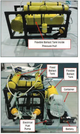
ROV is to perform underwater activities by replacing the function of a diver who needs to dive deeply into the water, in which he would face various risks such as pressure depth and danger at the bottom of the ocean. Tehrani, et. al 2010 [1] quoted that Remotely Operated Underwater Vehicle plays an important role in marine industries, especially in the construction of offshore oil and gas facilities. The ROV consists of a mechanical part, which considers the hardware and controlling part that covers the electronic components. The mechanical part of the basic ROV is classified into three categories, which are the ballast tank, thrusters and pressure hull [2]. Besides that, there are other additional components such as camera, manipulator or GPS systems for more functions. Figure 1 shows the complete prototype of UTeRG ROV that has been built by the Underwater Technology Research Group, Faculty of Electrical Engineering UTeM in 2012. The details and design specification of UTeRG ROV can be referred to [3 – 5].
previously known, the two concepts to depth control is using thruster, and another one is by a flexible ballast tank system.
Figure 1: Prototype of UTeRG ROV
One of the important components that helps in controlling the buoyancy of the ROV is the ballast tank system [9]. The ballast tank helps the ROV to move in vertical motion, in which it deals with upward and downward by controlling the volume of water inside the tank by removing water and inserting water into the tank in order to control the ROV’s buoyancy force. When the water is filled into the tank, it will help the ROV to add its weight and thus will make ROV move downward and vice versa. The research from NOAA (National Oceanic and Atmospheric Administration) stated that thrusters also could control the upward and downward motion of the ROV, but when reaching the saturated point in which the underwater depth pressure is high, the performance of the motor for the thrusters becomes worst and finally saturated. This will make the ROV no longer able to move downward [10]. The ballast tank can help to overcome this problem by
performing their function of adding the weight for the ROV through inserting the water. This function is able to help ROV moves deeper. Furthermore, this system can help in reducing the power consumption to make the ROV move in vertical motion with a more precise control. This research attempted to provide a new system in the development of underwater research in UTeM by developing a new system to improve the ROV functionality by applying an auto depth control system. This system can help the ROV to stay at a constant desire depth when exploring under water.
The previous project called “UTeRG-ROV” has already invented the ROV with ballast tank, but it is not auto depth controlled. It operated using the portable control that is a remote control. The ROV was not equiped with auto depth function in which the ROV cannot stay at constant depth for surveillance activities and taking data. It is difficult for humans to control the ROV to maintain constant at a certain depth. Besides that, UTeRG-ROV’s prototype is an open frame and a small-scale ROV.In addition, it needs a third tank function to remove water from the ballast tank, which can contribute to the increasing amount of weight, space and material used. Hence, a new system of ROV with a novel design equipped with auto depth control is proposed to improve the existing system by using a flexible ballast tank as the part which can control the ROV buoyancy to emerge and submerge at a constant specific depth. This ROV project attempts to build a flexible ballast tank that has been implemented by adding a pressure sensor to activate as a feedback for ballast tank system in controlling the flow of water in the tank itself to a certain control depth. This also helps the expert to retrieve the data and perform surveillance under water at a constant specific depth desired. However, the ROV testing is limited to only 1.5 meters of underwater depth because of the water tank depth.
II. A FLEXIBLE BALLAST TANK SYSTEM
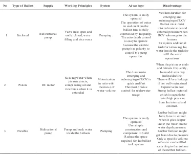
Table 1
Simple description of the three types of the ballast tank
No Type of Ballast Supply Working Principles System Advantage Disadvantage
1 Enclosed Bidirectional pump
Valve inlet open and water inside the tank for
refill the water There will be a leakage
if not well-maintained
3 Flexible Bidirectional pump Pump and suck water inside the balloon Pumping
The system is easily under the water due to
water depth pressure. Rubber balloon might get burst due to pressure
Only a specific volume of water can be filled according to the volume
of the rubber balloon.
The working principle of this type of pump is simple which is by controlling the polarity of the pump to generate its function. There are two sequences for the pump to operate, which are the clockwise (pump water inside/filling) and the counter-clockwise (suck water out/draining) flow sequence.
Figure 2 shows how the Prolux 1660 Electric Fuel pumps functions and can be referred in [13]. The most important thing to know is the valves that control the operation of filling and draining of the ballast tank. This needs an experiment to be conducted in order to know which valve that needs to be used, and the polarity connection to the relay used in this project.Figure 2 indicates that when the supply is given, the pump does the operation of filling the water. After the relay has been switched on, the operation also changes from filled to drained of water as shown in Figure 2.The ballast tank is an important component, for the ROV. Although a thruster can be used to control the ROV in vertical movement, it has saturated limit where the thruster can attend. Thus, with the help of a flexible ballast tank, ROV can travel deeper. Besides that, it brings a lot of advantages, such as reducing the power consumption that needs to move it down, increasing the stability of the ROV and allowing precise control reaction in vertical motion of the ROV.
.
Figure 2: Filling and Draining operation for Prolux 1660 electrical fuel pump
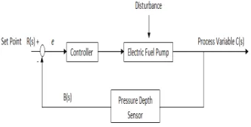
Figure 3: Block diagram of a closed loop system for ballast tank.
Firstly, the set point R(s) in voltage form is declared to where the desired depth for ROV to maintain. MPX 4250GP is designed to detect the pressure and convert it to voltage by referring to the rate of change of the depth. If the pressure increases, the voltage output will increase. The feedback voltage represents the actual change of depth of the ROV, and the signal is sent to the controller after being compared to the set point. The difference between set point R(s) and the pressure depth sensor output B(s) is represented by voltage error, ��������.
��������= �(�) − �(�) (1)
Where from Figure 3, a proportional controller for the system can be clarified by Equation 1:
���� = [�(�) − �(�)] ∗ �� (2)
Where;
Pout = Output of proportional controller Kp = Proportional gain
With reference to Equation 1, as the MPX4250GP goes deeper, the electric Prolux 1660 Electric Fuel Pump will pump the water until the controller receives zero voltage error at the desired set point depth. The controller will execute the function to switch the polarity of the electric fuel pump when the voltage output of pressure depth sensor exceeds the set point voltage. Equation 2 also shows the system is controlled by using the proportional controller. The controller output is proportional to the voltage error from the controller multiplied by the proportional gain in the system.
Figure 4: Simulation of ROV function through auto depth control of ballast tank
Figure 4 indicates the simulation in the auto depth control for unmanned underwater vehicle system using the ballast tank. The initial condition of the ballast tank is set to be in neutral buoyancy first, which is 90% submerged into the water and when force is given to the ROV, it will go down and the pump will function to pump in the water into the ballast tank instantly as the pressure sensor measures the pressure depth when traveling down until it reaches at the desired depth that has been set. The ROV will be in neutral buoyancy at the desired water level, and the ballast tank will be filled in with water. If the ROV is above the desired level, the pump will be draining water if the ROV goes down below the depth. This will make the ROV system capable to control and maintain its depth at a certain specified water level.
III. RESULTS
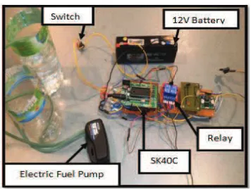
and further ease of modification of the electrical circuit later. Figure 6 shows the ROV tested on the lab tank test.
Figure 5: Complete assemble electrical circuit
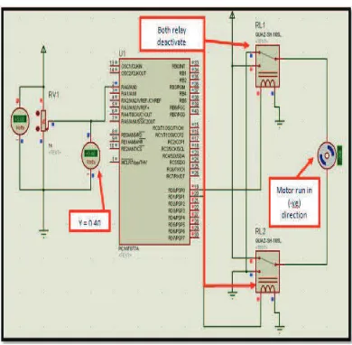
A. Software Development - Proteus Software
Before the real program is written and loaded into the PIC, a simulation project was made using the Proteus software. The pressure sensor MPX4250 and Prolux 1660 electric fuel pump were substituted with potentiometer and DC motor respectively, due to the Proteus software does not list those particular components. The components used are the voltmeter, potentiometer, PIC16F877A, two isolated relays and a DC motor. The function of the DC motor is regulated by the relay. The flow of the program is shown in Figure 7.
Figure 6: ROV Testing on Lab tank
Figure 7: Flow chart of simulation in Proteus
Figure 9: Simulation when Y > 0.39
Figure 8 and Figure 9 show the circuit simulation using Proteus software. Figure 8 shows that when the output sensor is below than 0.39V, the motor will be rotated in a positive direction, which means that water is filled inside the flexible ballast tank. Figure 9 shows that the motor will rotate in a negative direction, which means that water is drained out from the flexible ballast tank as output sensor is more than 0.39V.
B. Analysis of Filling and Draining Performance Analysis From the result obtained, the data is converted into a form of graph to get the comparison as shown in Figure 10.
Figure 10: Graph of Time Taken for Filling and Draining Operation of Ballast Tank in Atmospheric Pressure
From the result obtained, the time taken needed to fill the flexible ballast at the atmospheric pressure is around 80 seconds and for draining is 85 seconds. Hence, to study the relationship between that operation in atmospheric and underwater pressure, another experiment was conducted by placing the flexible ballast inside the ballast tank and the time taken for filling and draining process is fixed such as the atmospheric pressure tested in previous experiments to see the changes of rate of filling and draining under the water and at atmospheric surface. The results of the experiment are shown in Figure 11and Figure 12 where the graphs are compared between atmosphere and underwater pressure.
Figure 11: Percentage of Expanding Blood Medical Pocket against Time Taken
Figure 12: Percentage of Contraction Blood Medical Pocket against Time Taken
From both Figure 11 and 12, it shows the percentage of water filling the flexible ballast for two different pressures which atmospheric and underwater pressure. Based on the graph, it can be concluded that the pump performing filling operation is faster in atmospheric pressure compared to
No. of test
underwater pressure. However, the pump responds quickly underwater in the draining process. In the atmospheric pressure, the pump only needs ±80.6 seconds to complete filling, but when it goes underwater, 80.6 seconds is tested. However, the blood medical pocket has only achieved 80% expansion as the blood medical pocket can still be squeezed as compared to the previous experiment. It needs ±100.2 seconds to perform full filling process. On the other hand, for the draining operation, underwater react faster as it performs fully drain in only ±80.0 seconds compared in the atmospheric pressure, that is ±85.0 seconds. All of these situations are correlated with the surrounding pressure that acts to the system. In the draining process, the pressure exerted to the blood medical pocket helps in the process of removing water. The surrounding pressures have pressed the blood medical pocket to easily remove the water and make the operation to be quicker.
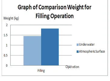
Figure 13: Graph Weight against Filling Operation for both levels
Figure 14: Graph Weight against Draining Operation for both levels
Next, Figure 13 and Figure 14 show the amount of weight of the blood medical pocket for filling and draining operation at both atmospheric pressure and underwater. The time being constant for each operation for this experiment where the filling is 83 seconds, and the draining is 90 seconds. The
profiles from both graphs show that the underwater reacted slower when inserting water for filling operation. However, it is quicker in the draining operation. This situation relates to the pressure issue as discussed previously. The results of this experiment strengthen the evidence to prove that the pressure gives a substantial impact towards both filling and draining operations for flexible ballast in the system.
IV. CONCLUSION
ACKNOWLEDGEMENT
Special appreciation and gratitude to the Universiti Teknikal Malaysia Melaka, (UTeM) and the Universiti Teknologi Malaysia, (UTM) and the Centre of Research and Innovation Management (CRIM) especially to the Faculty of Electrical Engineering for providing the financing, as well as moral support to complete this project successfully.
REFERENCES
[1] Nima Harsamizadeh Tehrani, Mahdi Heidari, Yadollah Zakeri and Jafar Ghaisari "Development, Depth Control and Stability Analysis of an Underwater Remote Operated Vehicle (ROV)", pp 814 - 819, June 2010.
[2] Manrique M.S, Nino M.S."Importance of a Methodology to Evaluate Technology of Remote Operated Vehicles (ROV'S) for Deep Waters". International Petroleum Conference and Exibition of Mexico, 1996. [3] Aras M. S. M., Azis, F.A, Othman, M.N., Abdullah, S.S. A Low Cost 4
DOF Remotely Operated Underwater Vehicle Integrated With IMU and Pressure Sensor. In: 4th International Conference on Underwater System Technology: Theory and Applications 2012 (USYS'12), pp 18-23, 2012.
[4] Aras, M.S.M, S.S. Abdullah, Rashid, M.Z.A, Rahman, A. Ab,Aziz, M.A.A, Development and Modeling of underwater Remotely Operated Vehicle using System Identification for depth control, Journal of Theoretical and Applied Information Technology, Vol. 56 No 1, pp 136-145, 2013.
[5] Aras, M.S.M, S.S. Abdullah, Rahman, A.A., Aziz, M.A.A., Thruster Modelling for Underwater Vehicle Using System Identification Method, International Journal of Advanced Robotic Systems, Vol. 10, No 252, pp 1 – 12, 2013.
[6] S. A. Woods, R. J. Bauer, M. L. Seto, and S. Member, “Autonomous Underwater Vehicles,” Automated Ballast Tank Control System for Autonomous Underwater Vehicles, pp. 1–13, 2012.
[7] Ali, F. A., Azis, F.A., Aras, M.S.M., Othman, M.N. and Abdullah, S.S. (2013) “Design A Magnetic Contactless Thruster of Unmanned Underwater Vehicle” International Review of Mechanical Engineering (I.RE.M.E.), 7 (7). pp. 1413-1420. ISSN 1970-8734.
[8] Ali, F. A., Aras, M.S.M., Azis, F.A., Sulaima, M. F. and Jaaffar I. (2013) “Design and Development of Auto Depth Control of Remotely Operated Vehicle (ROV) using Thruster System”. In: Malaysian Technical Universities International Conference on Engineering & Technology (MUCET), 3-4 December 2013, Kuantan, Pahang. [9] K. S. Wasscrman, L. Mathicu, M. I. Wolf, A. Hathi, and E. Fried,
“Dynamic Buoyancy Control of an ROV using a Variable Ballast Tank,” pp. 2888–2893.
[10] H. Bohm, Build your Underwater Robot. WestcoastWords, 1998 [11] M. Worall, A. J. Jamieson, A. Holford, and R. D. Neilson, “A variable
buoyancy system for deep ocean vehicles,” vol. 44, no. 0, 2007. [12] W. H. Wang, X. Q. Chen, a. Marburg, J. G. Chase, and C. E. Hann,
“Design of low-cost unmanned underwater vehicle for shallow waters,” International Journal of Advanced Mechatronic Systems, vol. 1, no. 3, p. 194, 2009.
[13] George R. Keller, P.E. Hydraulic System Analysis. Book 2, Chapter 15: Pumps, September 27, 2009
[14] Douglas R. Levin, Krista Trono and Christine Arraste "ROVs in a Bucket", Contagious, Experimental Learning by Building Inexpensive Underwater Robots, pp. 120 - 200, 2007
[15] Shanghai Fosun Medical, Shanghai Science & Technology I/E Co. ltd,` Single blood bag’. Internet: http://www.86surgical.com/Fosun -Medical-Blood-bags/, 2010 [accessed on 14/9/2013].