LOAD CAPACITY OF FLOATING RAFT-PILE
Abdul Hakam1), Novrial2) , Imam Faisal Pane3)
1)Staf Pengajar Jurusan Teknik Sipil Universitas Andalas 2) 3)Staf Pengajar Program Studi Magister Teknik Arsitektur USU
Abstrak. Penaksiran kapasitas total daya dukung sistem tiang-rakit mengapung (floating raft-pile system) yang
diperlakukan dengan pembebanan aksial diperkenalkan di sini. Analisa yang diusulkan didasarkan pada rumusan konvensional dan prototipe pondasi yang diuji di laboratorium. Kedua model tiang dan rakit dibuat dari dua material berbeda, beton dan kayu. Di laboratorium, tiap-tiap tiang dipancangkan ke dalam tanah liat yang lembut dan kemudian dibebani secara terpisah. Pemberian beban aksial dan penurunan vertikal model dicatat. Kapasitas batas untuk tiap-tiap tiang tunggal diperkirakan dari kurva beban-penurunan (load-displacement curve) yang dihasilkan dari uji tersebut. Uji beban aksial pada setiap pondasi rakit juga dilaksanakan. Kemudian kelompok tiang pancang ditekan untuk mendapatkan kurva beban-penurunan pondasi tersebut. Terakhir, pondasi tiang-rakit (raft pile foundation) diuji dengan cara yang sama. Perilaku pondasi tiang-rakit dalam kaitan dengan kurva beban-penurunan kemudian yang diselidiki. Di dalam tulisan ini, untuk menaksir kapasitas tiang aksial dan efisiensi kelompok tiang untuk tiang di dalam tanah liat yang ditinjau dianalisis dengan rumusan. Kalkulasi yang menggunakan rumusan tersebut dibandingkan dengan pengujian laboratorium. Kapasitas aksial pondasi tiang-rakit mengapung pada tanah liat dapat disimpulkan lebih tinggi dibandingkan dengan kapasitas kombinasi tiang dan rakit. Untuk aplikasi praktis, rumus kombinasi untuk menaksir total kapasitas beban pondasi mengapung di dalam tanah liat lembut dapat diusulkan.
Katakunci: sistem tiang-rakit, pondasi mengapung, kapasitas daya dukung
1. Introduction
Davis and Poulos (1972) proposed the method for analysing and designing the raft-pile system. Indeed, the scheme for solving the problem is based on the analysis of the group of the pile rather than the behaviour of the system. Moreover, the proposed formulas are inadequate to be adopted for describing the behaviour of the system.
When a group of piles is made up of several individual piles, the load capacity of the group cap may not be the same as the sum of the load capacity piles. The effect of grouping the piles arises the different amount of the group capacity and the sum of the individual contributing piles in term of efficiency of the pile group. Based on the studies done in the past, a number of references have suggested the formulas to estimate the pile group efficiency (ex. Das 1990, Bowles 1988).
However, the formulas do not include the effect of the cap which plays the important roles to group the piles. Even the pile cap commonly poured directly on the ground, the effect of the cap to transfer the load to the underneath soil was ignored. Except for piles in rock, Bowles (1988) suggested the use of the virtual block capacity based on the shear around the block plus the block bearing point instead of sum of the capacity of the piles. Then, Das (1990) recommended adopting the lower values between those two amounts as the ultimate load of the group.
can not be figured. However in the practice, the foundation is made of number of single piles which individually has a load capacity and a cap on the ground.
piles and the cap to the pile group bearing capacity are elaborated. The term of the group efficiency formula is nevertheless used to outline the load capacity of each element composed a raft-pile foundation. The suggestion procedures for estimating load capacity of the raft-pile system floating in soft clays are outlined.
2. Load Capacity
2.1. Load Capacity Of A Pile In Clay
In most cases, the load capacity of piles is combinations of the pile tip bearing and skin friction resistance along the piles. The calculation of the ultimate axial load capacity of individual pile can be carried out based on Terzaghi’s Like Formulas using the soil parameters.
For undrained saturated clays with zero internal friction angles, the ultimate point bearing capacity can be expressed as follows;
QP = AP Cu(p) Nc
where Cu(p) is undrained cohesion soil strength at the pile tip, AP is the cross section area of the pile tip and Nc is the bearing capacity factor. The value of Nc is vary depending on the method used for determining the load capacity, that is 9 for Meyerhof’s and 5,7 for Janbu’s one.
The skin friction resistance of pile in clay can be determined using one of several available methods. The methods assume that the skin resistance caused by passive lateral pressure at any depth of the pile and/or by between the pile and the soil. When the undrained cohesion of the soil, Cu, is used, the unit skin friction of every section of the pile length can be expressed by the equation (Vijayvergiya and Focht, 1972, after Das, 1990);
f = λ(σv’+2Cu)
where λ is an empirical factor ranges from 0.5 at surface then gradually decreases to 0.4 for 3 m depth of penetration, 0.3 for 7m, 0.2 for 16 m and 0.12 for 40 m and more.
The unit skin friction of every section of the pile length can also be expressed only in the terms of the adhesion factor by the following equation;
f = αCu
where α is an empirical adhesion factor. The value of α ranges from 1 for Cu < 50 kN/m2, then gradually decreases to 0.5 for Cu = 100 kN/m2 and 0.25 for Cu > 250 kN/m2.
Once the value of the unit skin resistance f has been obtained, the total frictional resistance of the pile can be calculated as the sum of the skin resistance each section of ΔL;
QS = Σ( fΘΔL)
Where Θ is the perimeter of the pile in the length section of ΔL. For practical purposes, the ultimate bearing capacity is divided by a safety factor, SF, of 1.5 to 4.0.
2.2. Ultimate Load Capacity Of Pile Groups
The ultimate axial load capacity of group piles in clay can be estimated using the general procedures as follow:
Firstly, determine the total load of the piles which includes the point capacity on the pile tip and skin friction resistances:
QT1 = Σ (QP + QS)
If the number of the pile in a square group in one direction is n1 and n2 in the other way, the by substituting the end capacity of pile and the skin friction formulas, the total load can be written as:
QT1 = n1n2 [ AP Cu(p) Nc+ Σ (αCuΘΔL)]
Secondly, determine the ultimate capacity of the group piles by assuming as solid block foundation. The dimension if the virtual block is Lg and Bg for horizontal direction and L (equal to the pile length average) for vertical one. Then by adopting the equation for individual pile capacity, the total load of the block is in terms of:
QT2 = AB Cu(p) Nc + Σ 2(Lg+Bg) Cu ΔL
Finally, the lower of the two values is referred to the ultimate load of the group QT(g).
Efficiency of pile groups
When several piles bonded by a cap in a group, the load capacity may be different from the sum of the several individual pile loads. If the total load at the cap is equal to sum of the individual pile loads, the efficiency of the group, Eg, is equal to 1. Then, the general definition of the pile group efficiency is;
capacity
For rectangular group of friction (floating) piles with the number of pile n in row and m in column, the Bridge Specifications of AASHTO suggests to estimate the efficiency of the pile groups as;
where θ= tan-1 D/s in degrees, D is the diameter of individual pile and s is the centre-to-centre spacing.
2.3. Load Capacity Of A Shallow Raft In Clay
When the shallow raft foundation is supported by a fairly soft soil, the failure surface in the soil will not extend to the ground surface. Such a failure type can be identified as the punch failure. Terzaghi has presented a comprehensive
theory for evaluation the load capacity of shallow foundation. Here, the formula is then employed to estimate the bearing capacity of a raft foundation.
The general expression of the ultimate load capacity is in the form;
Qu = Ab Ft Cu Nc*
where Cu is undrained cohesion soil strength at the foundation base, Ab is the cross section area of the foundation and Nc* is the bearing capacity factor. The value of Nc is vary depending on the internal friction angle of the soil. For undrained shear strength of saturated clays with zero internal friction angle, the factor is 5,14 ( After Das, 1990). Ft is the factor expresses the type of the shear failure type of the soil under the foundation. For the general shear failure of square footing is considered, the Ft is equal to 1,3 and for the local shear failure considered, then it is 0,867. Then, for strip foundation, the value is reduced by the factor of 0,77. If the punched shear failure is considered, the Ft value must be less than those values. In the last section of this paper, the value Ft for punch failure is discussed.
For practical purpose, the net allowable bearing capacity of raft foundations in undrained saturated clay can be expressed in the form;
Qall = Fd Ab Cu
where Fd is a factor depend on the depth-width ratio, it is 1 for foundation on ground surface and equal to 3 for the depth-width ratio of 3,0. The safety factor of about 3 is used to set up the above formula. However, the above formula is not recommended for foundations in soft clay.
3. Prototype Test
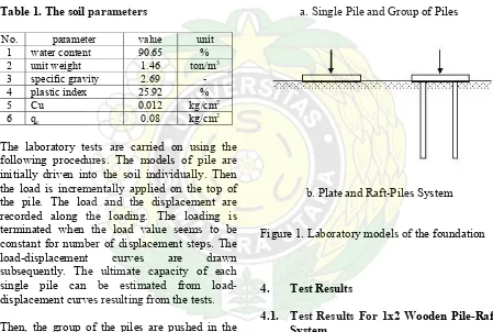
with the parameters as shown in the table 1. In this report, the piles and the plate are made of concrete. Since the clay is soft, the strength and the elasticity of the piles and the plate materials are assumed to be much stiffer than the soil. Then the behaviour of the soil-foundation system depends on the entire system than the material of the structures. The pile is 1.5 cm in the diameter and 30 cm of length. The centre to centre space of piles in group is 7.5 cm which is equal to 5 times the diameter of the piles. The wooden plate is 15 cm x 5 cm, the concrete plate is 15 cm x 15 cm of the area and 2 cm of the thicknesses.
Table 1. The soil parameters
No. parameter value unit 1 water content 90.65 % 2 unit weight 1.46 ton/m3 3 specific gravity 2.69 - 4 plastic index 25.92 % 5 Cu 0.012 kg/cm2
6 qc 0.08 kg/cm2
The laboratory tests are carried on using the following procedures. The models of pile are initially driven into the soil individually. Then the load is incrementally applied on the top of the pile. The load and the displacement are recorded along the loading. The loading is terminated when the load value seems to be constant for number of displacement steps. The load-displacement curves are drawn subsequently. The ultimate capacity of each single pile can be estimated from load-displacement curves resulting from the tests.
Then, the group of the piles are pushed in the same way in to the clay. The axial load the applied on the centre of the pile group to obtained the load-displacement curve of the foundation. The load-displacement curves of the pile group are also drawn subsequently. In the same way, the raft pile foundation and the separate plate on the clay are tested.
There are two types of raft-pile system tested in the laboratory, the first is 2x1 wooden raft-pile system sand the other one is 2x2 concrete raft-pile foundation. The procedures used in laboratory for the both foundations are the same.
a. Single Pile and Group of Piles
b. Plate and Raft-Piles System
Figure 1. Laboratory models of the foundation
4. Test Results
4.1. Test Results For 1x2 Wooden Pile-Raft System
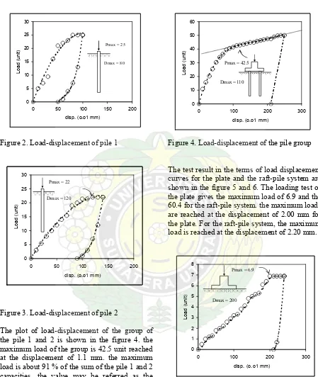
Figure 2. Load-displacement of pile 1
Figure 3. Load-displacement of pile 2
The plot of load-displacement of the group of the pile 1 and 2 is shown in the figure 4. the maximum load of the group is 42.5 unit reached at the displacement of 1.1 mm. the maximum load is about 91 % of the sum of the pile 1 and 2 capacities. the value may be referred as the efficiency of the group.
Figure 4. Load-displacement of the pile group
The test result in the terms of load displacement curves for the plate and the raft-pile system are shown in the figure 5 and 6. The loading test of the plate gives the maximum load of 6.9 and the 60.4 for the raft-pile system. the maximum loads are reached at the displacement of 2.00 mm for the plate. For the raft-pile system, the maximum load is reached at the displacement of 2.20 mm.
Figure 5. Load-displacement of the plate
0 5 10 15 20 25 30
0 50 100 150 200
disp. (o.o1 mm)
Load (unit)
Pmax = 25
Dmax = 80
0 1 2 3 4 5 6 7 8
0 100 200 300
disp. (o.o1 mm)
Load (
uni
t)
Pmax = 6.9
Dmax = 200
0 5 10 15 20 25 30
0 50 100 150 200
disp. (o.o1 mm)
Load (unit)
Pmax = 22
Dmax = 120
0 10 20 30 40 50 60
0 100 200 300
disp. (o.o1 mm)
Load (unit
)
Pmax = 42.5
Dmax = 110
0 1 2 3 4 5 6 7 8
0 100 200 300
disp. (o.o1 mm)
Load (unit)
Pmax = 6.9
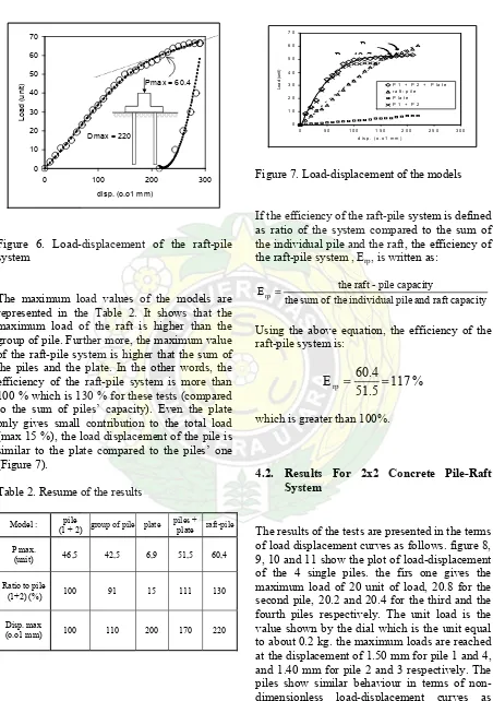
Figure 6. Load-displacement of the raft-pile system
The maximum load values of the models are represented in the Table 2. It shows that the maximum load of the raft is higher than the group of pile. Further more, the maximum value of the raft-pile system is higher that the sum of the piles and the plate. In the other words, the efficiency of the raft-pile system is more than 100 % which is 130 % for these tests (compared to the sum of piles’ capacity). Even the plate only gives small contribution to the total load (max 15 %), the load displacement of the pile is similar to the plate compared to the piles’ one (Figure 7).
Table 2. Resume of the results
Model : (1 + 2) pile group of pile plate piles + plate raft-pile
Figure 7. Load-displacement of the models
If the efficiency of the raft-pile system is defined as ratio of the system compared to the sum of the individual pile and the raft, the efficiency of the raft-pile system , Erp, is written as:
capacity
Using the above equation, the efficiency of the raft-pile system is:
%
117
51.5
60.4
E
rp=
=
which is greater than 100%.
4.2. Results For 2x2 Concrete Pile-Raft System
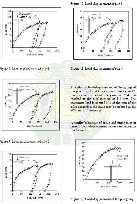
Figure 8. Load-displacement of pile 1
Figure 9. Load-displacement of pile 2
Figure 10. Load-displacement of pile 3
Figure 10. Load-displacement of pile 3
Figure 11. Load-displacement of pile 4
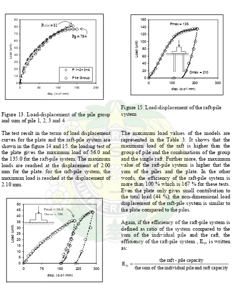
The plot of load-displacement of the group of the pile 1, 2, 3 and 4 is shown in the figure 12. the maximum load of the group is 76.4 unit reached at the displacement of 1.1 mm. The maximum load is about 94 % of the sum of the piles capacities. the value may be referred as the efficiency of the group.
A similar behaviour of group and single piles in terms of load-displacement curves can be seen in the figure 13.
Figure 12. Load-displacement of the pile group
Figure 13. Load-displacement of the pile group and sum of pile 1, 2, 3 and 4
The test result in the terms of load displacement curves for the plate and the raft-pile system are shown in the figure 14 and 15. the loading test of the plate gives the maximum load of 36.0 and the 135.0 for the raft-pile system. The maximum loads are reached at the displacement of 2.00 mm for the plate. for the raft-pile system, the maximum load is reached at the displacement of 2.10 mm.
Figure 14. Load-displacement of the plate
Figure 15. Load-displacement of the raft-pile system
The maximum load values of the models are represented in the Table 3. It shows that the maximum load of the raft is higher than the group of pile and the combinations of the group and the single raft. Further more, the maximum value of the raft-pile system is higher that the sum of the piles and the plate. In the other words, the efficiency of the raft-pile system is more than 100 % which is 167 % for these tests. Even the plate only gives small contribution to the total load (44 %), the non-dimensional load displacement of the raft-pile system is similar to the plate compared to the piles.
Again, if the efficiency of the raft-pile system is defined as ratio of the system compared to the sum of the individual pile and the raft, the efficiency of the raft-pile system , Erp, is written as:
Using the above equation, the efficiency of the raft-pile system is:
%
125
108.4
135
E
rp=
=
which is more than 100%.
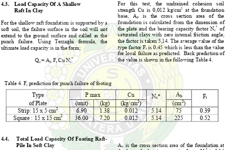
4.3. Load Capacity Of A Shallow Raft In Clay
For the shallow raft foundation is supported by a soft soil, the failure surface in the soil will not extend to the ground surface and called as the punch failure. Using Terzaghi formula, the ultimate load capacity is in the form;
Qu = Ab Ft Cu Nc*
For this test, the undrained cohesion soil strength Cu is 0,012 kg/cm2 at the foundation base, AP is the cross section area of the foundation is calculated from the dimension of the plate and the bearing capacity factor Nc* of saturated clays with zero internal friction angle, the factor is taken 5,14. The average value of the type factor Ft is 0.45 which is less than the value for local failure as predicted. Back prediction of the value is shown in the following Table 4.
4.4. Total Load Capacity Of Foating Raft-Pile In Soft Clay
For practical application of Raft-pile foundation floating in soft clay, the following procedure can be considered. The total load capacity of the system is proposed;
QT = QR + Σ (QP + QS)
Where QR is the load capacity of the Raft (in case of pile group is the cap), QP and QS are the bearing capacity of the pile at the tip and on skin respectively.
The resistance of square raft foundation is predicted using the ultimate load capacity in the form;
Qu = Ab Ft Cu Nc*
Ab is the cross section area of the foundation at the base, the bearing capacity factor Nc* is 5,14 and the value of the type factor Ft is 0.45 which represents the value for the punch failure. However, for strip foundation with length-width ratio equal greater than one and a half, the ultimate luad capacity Qu must reduced by the factor of 0,77.
The ultimate point bearing capacity of pile can be estimated using;
QP = AP Cu(p) Nc
where Cu(p) is undrained cohesion soil strength at the pile tip, AP is the cross section area of the pile tip and Nc is the bearing capacity factor, it is 9 for Meyerhof’s and 5,7 for Janbu’s one. However, since the piles are considered as Table 3. Resume of the results of 2x2 piles
Model : pile
(1+2+3+4) group of piles
plate (15cmx15cm)
piles + plate
raft-pile system P max. (unit) 81 76,4 36 117 135
Ratio to pile (1+2+3+4) % 100 94 44 144 167
Disp. max (o.o1 mm) 100 130 210 210 210
Table 4. Ft prediction for punch failure of footing
Type P
max
Cu
N
c*
A
bF
tof Plate
(unit)
(kg)
(kg/cm
2) (cm
2)
Strip: 15 x 5 cm
26.90 1.38 0.012 5.14 75 0.39
floating one, the tip resistance is not significant to contribute the pile capacity. Then, for the skin resistance;
QS = Σ (fΘ∆L) with
f = λ(σv' + 2Cu) or
f = αCu
5. Conclusions
The laboratory tests raft-pile foundations subjected to vertical axial loading presented in this paper give the behaviour of the models in the terms of load-displacement curves. The axial load capacity of the raft-piles foundations floating on clays can be concluded higher than the combination of the piles capacity. The piles give dominantly contribution to the raft-pile system in terms of load capacity compared to the plate. However, the behaviour of the raft-pile system appears to be the similar to the single plate one. The efficiency of the raft-pile system can be estimated as the ratio of the system capacity compared to the sum of the capacity of the contributing elements of the system. Since the efficiency of the raft-pile system is greater than the sum of pile and raft capacities, it is
suggested that for practical propose to use the sum value of the piles and the raft.
References
Valliappan, S., Tandjiria, V. and Khalili, N., 1999, ‘Design of Raft-pile Foundation Using Combined Optimization and Finite Element Approach’, Int. Journal for Numerical and Analytical Methods in Geomechanics, Vol. 23, pp 1043-1065.
Das, B. M., 1990, Principles of Foundation Engineering, PWS-KENT Publishing Company, Boston.
Bowles, J. E., 1988, Foundation Analysis and Design, McGraw-Hill Book Company, Singapore.