PARAMETRIC STUDIES FOR OBTAINING THE DIMENSION OF SOIL IMPROVED AREA
Budijanto Widjaja
Building E-2 Office : 604-1, Department of Construction Engineering National Taiwan University of Science and Technology
43 Keelung Road, Section 4, Taipei 106, Taiwan ROC Email : [email protected]
Department of Civil Engineering, Parahyangan Catholic University Jl. Ciumbuleuit 94, Bandung 40141, Indonesia
Email : [email protected]
ABSTRACT
In many cases, to improve weak soil (e.g. grouting method or other method), it must have the obvious understanding about the design of appropriate size of soil improved area, for example, road projects or deep excavation projects. The essential input parameters are a certain width, a depth, and also the improved area stiffness. The important question is why it is generally recommended to make deeper area than performing wider area. This question can be answered with parametric studies by using the Beam on Elastic Foundation Method which is proposed by Hetenyi (1946). Soil in this method is modeled as Winkler's spring. And also, the relevant information of the soil settlement related to the soil stiffness and that spring could be analyzed with this approach. In this paper, the design chart is developed with considering several of simple combinations among the contact load pressures, the appropriate sizes, and the stiffness of improved area (e.g. improved soil modulus). So, the deeper improved soil is simulated and shown that if the improved soil thickness is increased, the settlement will be reduced. But, for another case with particular loading condition and soil stiffness, there is no effect if the area of improved soil is wider and the behavior is similar and goes through the same one pattern only. In this paper, it is developed the design curve considering the load acting on the improved soil area, modulus of improved area parameters and soil modulus of subgrade reaction, the normalized curve for getting improved area thickness and width is generated. It is shown if the load is increased then the width of improved soil area has to be increased for a certain thickness. Because of linear elastic approach, it is shown that the variation of five parameters (soil modulus, of improved area, load, thickness and length of improved area, and modulus of subgrade reaction) gives the same curves for each combinations of certain value of k/su. Using this normalized design chart as a function of pressures, width of loading, a soil width and thickness, and soil stiffness, it can be used as the appropriate preliminary dimension of improved soil area.
Keywords : soil improved area, beam on elastic foundation method, design chart
INTRODUCTION
This paper has an aim to show the using of beam on elastic foundation proposed by Hetenyi (1946) to get parametric study for obtaining the geometry of an improved area zone. By this appropriate method, one can get any relevant information about deformation and moment and also shear stress. Due to its simplification, there are only three main parameters in this method which are modulus of subgrade reaction (ksoil), modulus
elasticity of ground improvement area (E), and its inertia (I). Soil is modeled by k as a Winkler’s spring (1867).
MODULUS OF SUBGRADE REACTION Definition of Modulus of Subgrade Reaction (k)
Parameter k is defined as ratio of stress and settlement. So, the dimension of k is in F/L3 which F
is force and L is length. This concept is a simplified mathematical equation of an elastic soil model.
Obtaining k
The modulus of subgrade reaction (k) can be obtained using two approaches. One approach is stability approach and another is deformation approach. California Bearing Test (CBR) can be used to find the value of k (Coduto, 2001). In the CBR test result, it obviously shows the relationship between stress and settlement. So, the value of k can be obtained by divided the stress and the settlement.
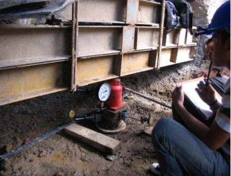
load cell (or manometer) is used. While finding out the settlement, the settlement dial gauge is used. In the base, a 30 cm or 60 cm in diameter steel plate (Figure 1) is usually used.
Figure 1. Obtaining Modulus Subgrade of Reaction using Plate Loading Test.
Because of the limitation of available data and the uncertainty of soil condition, it is proposed to use the empirical equation. Ou (2006) suggested the following empirical equations to estimate k value both in clay and sand. The equations are
Clay : k = 40– 50 su(t/m 3
) (1)
Sand : k = 70– 100 NSPT (t/m 3
) (2)
where su is an undrained shear strength (t/m 2
) and NSPTis a value of Standard Penetration Test.
APPLICATION OF MODULUS SUBGRADE REACTION
The implementations of this modulus in geotechnical engineering field are useful in raft design, pile raft design, and also the special case in soil improvement (i.e. grouting). In this paper, the author proposes the using of this method to find out the dimension in soil improved area.
THE BEAM ON ELASTIC FOUNDATION FORMULA
Assumptions
In this paper, the assumptions are limited as follows:
Soil type below improved area is homogenous (clay or sand)
The improved area is assumed as flexible beam
These are a plane strain and an elastic case
A cross section of improved area is same
Distributed loading is applied above improved area
So, the problem assumptions are presented in figure 2. The soil is modeled by value of k. The improved area has three parameters such as modulus of elasticity (E), inertia moment (I), and Poisson’s ratio (). This improved area has a dimension of thickness (z) and length (L). Above this improved area, there is a distributed loading (q) which has a certain width (B).
Solution
The basic equation of beam on elastic foundation method is:
q ky dxy d
EI 4
4
(3)
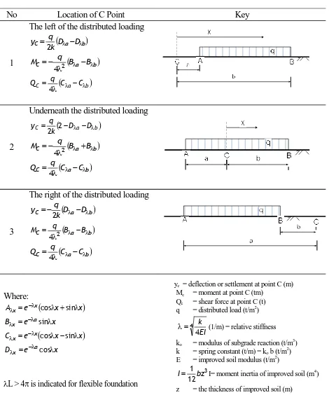
To get the solution of this problem, it is suggested to use the equations as tabulated in table 1.
Ou (2006) and Liao (2007) suggested modeling the composite soil bodies subjected to vertical loading and unloading using the principle of force equilibrium. The modulus of treated soil is higher, i.e. 100 times, than untreated soil. Hence, the improved area can be treated having inertia. This application is always used in engineering practice in Japan and Taiwan.
THE RESULTS FROM BEAM ON ELASTIC FOUNDATION
Wider Area versus Deeper Area
From parametric studies, it is shown that making a thicker area is better than making a wider area. Because in wider improved area, the reaction curve (i.e. deflection) follows the certain path and as a result providing one curve only and the range of a curve just depends on the width of improved area and or width or load.
Deflection Curve
-0.5
0
0.5
1
1.5
2
2.5
3
0 1 2 3 4 5 6 7 8 9 10
Distance (m)
S
et
tle
m
en
t (
cm
) z = 0.5 m
z= 1.0 m
z = 1.5 m z = 3.0 m
Table 1. Beam on Elastic Foundation Solution (After Hetenyi, 1946)
No Location of C Point Key
1
The left of the distributed loading a b
C qkD D y 2
a b
C q B B
M
42
a b
C qC C Q 4
2
Underneath the distributed loading
a b
C qk D D y 2 2
a b
C q B B
M
42
a b
C qC C Q 4
3
The right of the distributed loading a b
C qkD D y 2
a b
C q B B
M
42
a b
C qC C Q 4
Where:
x x
e
Ax x
cos sin x e Bx a
sin
x x
e
Cx x
cos sin x e Dx a
cos
L > 4 is indicated for flexible foundation
yc= deflection or settlement at point C (m)
Mc = moment at point C (tm)
Qc = shear force at point C (t)
q = distributed load (t/m2)
4
4kEI
(1/m) = relative stiffness
ko = modulus of subgrade reaction (t/m3)
k = spring constant (t/m) = ko b (t/m2)
E = improved soil modulus (t/m2)
3
12 1
bz
I I= moment inertia of improved soil (m4)
z = the thickness of improved soil (m)
In other, making a deeper improved area, it is shown the significant effect in reaction curves. Effect on thicker area is the settlement will be reduced. So, it is suggested to use deeper area than making a wider area.
Figure 3. Two Dimentional Modeling
For illustration as shown in figure 4, the values of c = 4.0 m, d = 3.0 m, l = 10.0 m, and z = 1.5 m is used. The distributed loading, q is 2 t/m2. For wider area, it is made by variety of d. For deeper area, it varies of z value. The result can be obviously shown in figure 4.
Figure 4. The Example for Calculation
In figure 6, it is clearly shown the effect of making improved soil deeper. If improved soil area is made thicker, then the settlement will be reduced, but moment and shear force is increased.
Design Chart
In development of design chart for getting a dimension of improved area using Beam on Elastic Foundation theory, it is assumed that improved area is a flexible material withL > 4 (refer to Table 1).
In this theory, the computation of settlement depends on the amount of distributed loading (q) above improved soil area. The stiffness of soil improved area (E) also influence the equation. The geometry of improved area is considered too. So, the calculation uses equations in Table 1.
In this parametric study, it is assumed that modulus of improved soil is 200 su (Duncan &
Buchignani, 1976) where su is undrained shear
strength. For modulus of subgrade reaction values, it is used a variety of k/su = 50 (Ou, 2006) and k/su
= 100. E/q is varied from 100 to 1000 with E is modulus of improved soil area and q is the distributed loading.
1.0 1.5 2.0 2.5 3.0 3.5 4.0 4.5
0.0 0.2 0.4 0.6 0.8 1.0 1.2 1.4 1.6 1.8 2.0
z/B
L
/B 100
k/su = 50
E/q100 200 500 1000
k/su = 50
E/q100 500 1000
k/su = 50
E/q 200 500 1000
1.0 1.5 2.0 2.5 3.0 3.5 4.0 4.5
0.0 0.2 0.4 0.6 0.8 1.0 1.2 1.4 1.6 1.8 2.0
z/B
L
/B
100
k/su = 100
E/q
500
1000 200
100
k/su = 100
E/q
500
1000 200
100
k/su = 100
E/q
500
1000 200
Figure 6. The Result for Thickness Variation of Improved Soil.
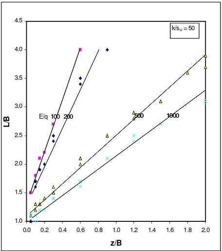
The normalized curve which has a relationship between z/B and L/B is presented in figure 6 and 7 for k/su = 50 and k/su = 100, respectively (z is
thickness of soil improved area, L is width of improved area, B is width of distributed loading, q is the working load).
In development of those charts, it is shown that the variation of five parameters (E, q, z/B, L/B, and k) gives the same curves for each combination of k/su. It is because this theory is based on linear elastic
approach.
It is shown that if the ratio of E/q is increased from 100 to 1000 (i.e. modulus of soil improved area is increased or load is reduced) then for a certain value of z/B, the value of L/B is reduced. The characteristic of this chart is, if modulus is increased then the width of area will be reduced. But, if the load is increased (or E/q is decreased) then the width will be increased.
For illustration, assumed the loading is q = 2 t/m2 in 4 m width, E = 1000 t/m2, and k/su = 50. For
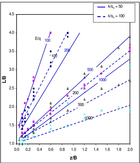
z/B is 0.5 and E/q = 500, from figure 7, the normalized length (L/B) is 1.7. It means the dimension of improved soil area is 2 m x 6.8 m. In figure 7, the minimum width of improved soil area is similar to the width of loading. It is shown on figure 7 and figure 8, the minimum value of L/B is 1.0. Figure 9 is a combination of figure 7 and figure 8. It is shown that for a certain number of z/B, for L/B value from k/su = 100 gives a shorter width if
compared to k/su = 50.
APPLICATION OF DESIGN CHARTS
The application of design chart is useful in deep excavation project for example to improve the soil in
excavation area. Another example project is for the road project. The type of ground improvement, for instance, can be the grouting method. Another appropriate method also can be used.
Figure 7. Design Chart for Obtaining Geometry of Soil Improved Area for k/su = 50
Figure 8. Design Chart for Obtaining Geometry of Soil Improved Area for k/su = 100 0
1 2 3
0 1 2 3 4
Soil Thickness z (m)
Settlement (cm)
Moment (tfm)
Shear Force (tf)
Se
ttl
em
en
t (
cm
)
M
om
en
t (
tfm
)
Sh
ea
r F
or
ce
(t
1.0 1.5 2.0 2.5 3.0 3.5 4.0 4.5
0.0 0.2 0.4 0.6 0.8 1.0 1.2 1.4 1.6 1.8 2.0
z/B
L
/B
100
1000 200
100 E/q
500
1000
200
500
k/su = 100 k/su = 50
Figure 9. Design Chart for Obtaining Geometry of Soil Improved Area
CONCLUSION
Using beam on elastic foundation method, several parametric studies are developed to find out the geometry of improved soil area.
There is no effect if the area of improved soil is wider. The response is similar and goes through the same one pattern only.
The deeper improved soil is simulated and shown that if the soil thickness is increased, the settlement will be reduced.
It is developed a design chart to determine the geometry of improved soil area. The chart refers to the ratio of soil improved area modulus and load, spring constant, normalized thickness and width of improved soil area.
Because of linear elastic approach, it is shown that the variation of five parameters (soil modulus, of improved area, load, thickness and length of improved area, and modulus of subgrade reaction) gives the same curves for each combination of certain value of k/su.
The characteristic of this design chart is, if the modulus is increased then the width of area will be reduced. But, if the load is increased (or normalized value of E/q is decreased) then the width will be increased.
Using this normalized design chart as a function of loading, width of loading, a improved soil width and thickness, and its stiffness, it can be
used for determining the appropriate preliminary dimension of improved soil area.
ACKNOWLEDGMENT
The author generously gives acknowledgment to Professor H.J. Liao in National Taiwan University of Science and Technology in Taipei, Taiwan. His support and appreciation to the author are valuable to purposely create this paper as a final project paper for his class.
REFERENCES
ASTM. 1994. Standard Test Methods for Bearing Capacity of Soil for Static Load and Spread Footing. ASTM D1194-94. West Conshohocken : ASTM.
Bruce, D.A. 1994. Permeation Grouting. Ground Control and Improvement. Xanthakos, P.P et al ed. New York : John Wiley & Sons, Inc. pp. 493– 579.
Charles, A. 2004. Ground Improvement : The Interaction of Engineering Science and Experienced-Based Technology. Ground and Soil Improvement. C.A. Raison ed. London : Institution of Civil Engineers, pp. 3– 8. Coduto, D.P. 2001. Foundation Design - Principles
and Practices. 2nd ed. New Jersey: Prentice Hall.
Duncan, J.M. and A.L. Buchignani. 1976, An Engineering Manual of Settlement Studies. Report. Department of Civil Engineering. Berkeley : University of California.
Das, B.M. 1984. Reinforced Earth Structures. Principles of Foundation Engineering. 3rd ed. Boston : PWS Publishing Company.
Hetenyi, M. 1946. Beams on Elastic Foundation : Theory with Applications in The Fields of Civil and Mechanical Engineering. Ann Arbor : University of Michigan.
Liao, H.J. 2007. Special Topics on Soil Improvement. Lecturer handout. Taiwan : National Taiwan University of Science and Technology.
Liong, G.T. 2004. Notes on The Application of The Spring Constant and Soil-Structure Interaction Problems. Plaxis Bulletin. Issue 16 October. pp 8– 11.
Ou, C.Y. 2006. Deep Excavation : Theory and Practice. London : Taylor & Francis.