ENGINEERING ANALYSIS ON SPREADER BEAM BY USING
MANUAL CALCULATION AND SOLIDWORKS SIMULATION
SOFTWARE
This report submitted in accordance with requirement of the Universiti Teknikal Malaysia Melaka (UTeM) for the Bachelor Degree of Manufacturing Engineering
(Manufacturing Process) (Hons.)
by
MOHD NOR EFFENDY BIN NEK MAN B 051010077
890628-08-5175
UNIVERSITI TEKNIKAL MALAYSIA MELAKA
BORANG PENGESAHAN STATUS LAPORAN PROJEK SARJANA MUDA
TAJUK: ENGINEERING ANALYSIS ON SPREADER BEAM BY USING MANUAL CALCULATION AND SOLIDWORKS SIMULATION SOFTWARE
SESI PENGAJIAN: 2012/13 Semester 2
Saya MOHD NOR EFFENDY BIN NEK MAN
mengaku membenarkan Laporan PSM ini disimpan di Perpustakaan Universiti Teknikal Malaysia Melaka (UTeM) dengan syarat-syarat kegunaan seperti berikut: 1. Laporan PSM adalah hak milik Universiti Teknikal Malaysia Melaka dan penulis. 2. Perpustakaan Universiti Teknikal Malaysia Melaka dibenarkan membuat salinan
untuk tujuan pengajian sahaja dengan izin penulis.
3. Perpustakaan dibenarkan membuat salinan laporan PSM ini sebagai bahan pertukaran antara institusi pengajian tinggi.
(Mengandungi maklumat TERHAD yang telah ditentukan oleh organisasi/badan di mana penyelidikan dijalankan)
Alamat Tetap:
FAKULTI KEJURUTERAAN PEMBUATAN
PENGKELASAN LAPORAN PSM SEBAGAI SULIT/TERHAD LAPORAN PROJEK SARJANA MUDA KEJURUTERAAN PEMBUATAN (MANUFACTURING PROCESS): MOHD NOR EFFENDY BIN NEK MAN
Sukacita dimaklumkan bahawa Laporan PSM yang tersebut di atas bertajuk
“Engineering analysis on spreader beam by using manual calculation and
SolidWorks simulation software” mohon dikelaskan sebagai *SULIT /
TERHAD untuk tempoh LIMA tahun dari tarikh surat ini.
2. Hal ini adalah kerana IANYA MERUPAKAN PROJEK YANG DITAJA OLEH SYARIKAT LUAR DAN HASIL KAJIANNYA ADALAH SULIT.
Sekian dimaklumkan. Terima kasih.
Yang benar,
________________
* Potong yang tidak berkenaan
NOTA: BORANG INI HANYA DIISI JIKA DIKLASIFIKASIKAN SEBAGAI SULIT DAN
TERHAD. JIKA LAPORAN DIKELASKAN SEBAGAI TIDAK TERHAD, MAKA BORANG INI TIDAK PERLU DISERTAKAN DALAM LAPORAN PSM.
UNIVERSITI TEKNIKAL MALAYSIA MELAKA
Karung Berkunci No.1752, Pejabat Pos Durian Tunggal, 76109 Durian Tunggal, Melaka
Tel : 06-331 6019/6429 Faks : 06-331 6411/6431
I hereby, declared this report entitled “ Engineering analysis on spreader beam by using manual calculation and SolidWorks simulation software” is the results of my
own research except as cited in references.
Signature : ……….
Author’s Name : MOHD NOR EFFENDY BIN NEK MAN
Date : 12 / 06 / 2013
APPROVAL
This report is submitted to the Faculty of Manufacturing Engineering of UTeM as a partial fulfillment of the requirements for the degree of Bachelor of Manufacturing Engineering (Process) (Hons.). The member of the supervisory is as follow:
………
i
ABSTRAK
Laporan ini berkaitan dengan projek industri yang menerangkan satu analisa kejuruteraan mengenai spreader beam yang digunakan di Syarikat M. Spreader beam adalah digunakan untuk mambantu proses mengangkat barangan khususnya untuk barangan yang panjang. Walau bagaimanapun, safe working load (SWL) bagi
spreader beam ini tidak ketahui. Analisis matematik dan Finite element analysis
(FEA) menggunakan SolidWorks 2011 perisian simulasi digunakan untuk mengenalpasti kebolehan untuk menahan beban berdasarkan reka bentuk spreader beam. Di dalam analisis ini, 1.5 Ton digunakan sebagai beban kerja. Beban ini adalah beban maksima bagi spreader beam yang telah dipilih. Berdasarkan pengiraan matematik tekanan maksima adalah 88.53 MPa manakala daripada FEA analisis tekanan maksima adalah 92.52 MPa. Terdapat 4.3% perbezaan antara kedua-dua keputusan ini. Had SWL adalah 95 MPa berdasarkan factor of safety lima. Kedua-dua keputusan ini tidak melebihi had SWL. Ini bermaksud, spreader beam ini selamat untuk mengangkat beban maksima yang digunakan oleh Syarikat M seberat 1.5 ton. Reka bentuk Lifting lug telah dicadangkan bagi meningkatkan prestasi
ii
ABSTRACT
iii
DEDICATION
iv
ACKNOWLEDGEMENT
First and foremost, I would like to express my appreciation to my final year project supervisor, Dr. Md Nizam Bin Abd Rahman and Production Manager Company M, Mr. Cheong Yew Leong for his guidance and support during completing this project.
Great appreciation also gives to my lectures and all staff in Faculty of Manufacturing Engineering especially to the technician that patient in helping during prepares the final product. Not forget, I am gratefully thanks to our colleague, Universiti Teknikal Malaysia Melaka (UTeM) for providing enough material and good facilities in the campus.
vi
2.5 SolidWorks 2012 Simulation software 18
2.5.1 Finite element analysis method using SolidWorks 2012 Simulation 18
2.6 Safe working load and factor of safety 21
CHAPTER 4: RESULT AND DISCUSSION 39
4.1 Information on the Spreader beam 39
4.2 Mathematical analysis 41
4.3 FEA analysis using SolidWorks 2011 49
4.3.1 Stresses and displacement study 50
4.4 Comparison between mathematical and FEA analysis 57
4.5 Safe working load 58
vii 4.6.1 Suggestion improvement spreader beam design 59
4.6.2 Mathematical analysis 61
4.6.3 FEA analysis using SolidWorks 2011 64
4.7 Comparison between before and after improvement design 66
4.8 Summary 68
CHAPTER 5: CONCLUSION AND RECOMMENDATION 69
5.1 Conclusion 69
5.2 Recommendation 70
REFERENCES
viii
LIST OF TABLES
3.1 Gantt chart 23
3.2 ASTM A36 Steel material properties 28
3.3 I-beam dimension and parameter 29
3.4 Formula for mathematical analysis 31
4.1 Material properties 40
4.2 Other properties 40
4.3 Mathematical analysis result 49
4.4 Model information 50
4.5 Material properties 51
4.6 Fixture 51
4.7 Load 52
4.8 Mesh information 53
4.9 Stress study result 54
4.10 Displacement study result 56
4.11 Comparison result 57
4.12 Result mathematical analysis 63
4.13 Stress study result 64
4.14 Displacement study result 66
ix
LIST OF FIGURES
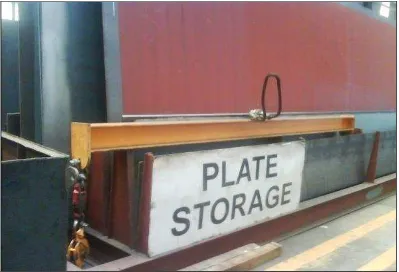
1.1 Spreader beam (Company M factory) 3
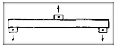
2.1 Basic spreader beam 6
2.2 Spreader beam with two upper lifting lugs 6
2.3 Shackles 6
2.4 Oblong, sling and hook 6
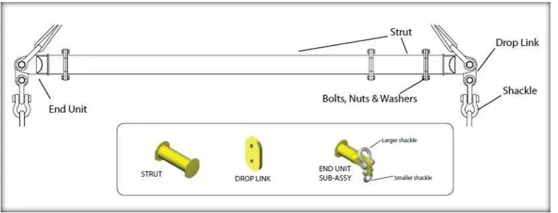
2.5 Modular spreader beam 7
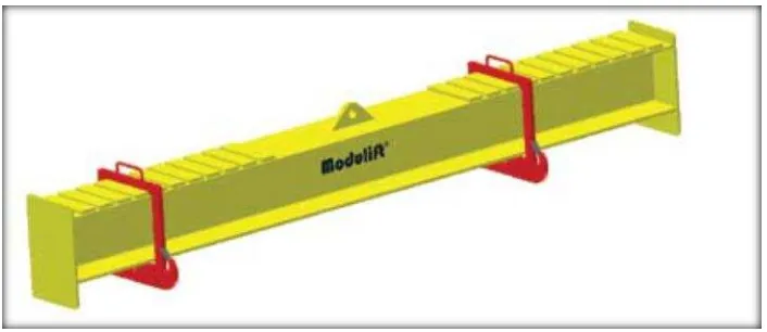
2.6 Fixed spreader beam 8
2.7 Castellated spreader beam 8
2.8 Telescopic spreader beam 9
2.9 H lifting frame 9
2.10 Spreader frame 10
2.11 Spreader beam 11
2.12 Sign conversion for shear and moment bending 13
2.13 Example of free body diagram, shear diagram and bending
moment diagram 13
2.14 Tension failure 16
2.15 Tearing tension fracture 17
2.16 Shear force 18
2.17 Mesh 20
2.18 Displacement plot 20
2.19 Stress plot 20
3.1 Methodology flow chart 24
3.2 Spreader beam dimension 27
3.3 Solid model of spreader beam 32
3.4 How to change a model material 33
3.5 Material window 33
x
3.7 Starting a new study 34
3.8 Fixture pane and Force/Torque pane 35
3.9 Mesh window and result folder 36
3.10 Mesh 36
3.11 Stress plot 37
3.12 Displacement plot 37
4.1 Free body diagram 42
4.2 Shear force diagram 42
4.3 Bending moment diagram 42
4.4 Fixture position 52
4.5 Load position 52
4.6 Von mises stress average 54
4.7 Center lifting lug stress analysis 55
4.8 Side lifting lug stress analysis 55
4.9 Existing spreader beam 59
4.10 Improvement design 59
4.11 Dimension for improvement design 60
4.12 Von Mises average 65
xi
LIST OF ABBREVIATIONS, SYMBOLS AND
NOMENCLATURE
A - Area I-beam ( )
AISC - American institute of steel construction
ASME - The American society of mechanical engineers ASTM - American Society for Testing and Materials
- Least plate width at side of holes (mm)
- Allowable ultimate tensile strength ( )
- Bending force ( )
Y - Perpendicular distance from neutral axis (mm)
σ
-
Stress1 This chapter explains the background of this research, company background, problem statement, objective, scope and introduction of spreader beam. This project has been carried out based on the industrial requirement from Company M.
1.1 Background
The background of this research is divided with two parts which is company background and project background.
1.1.1 Company background
Company M manufactures a comprehensive range of overhead travelling crane, hoist, warehouse truck and wide variety of industrial products such as gondolas, dock levellers, monorail systems and automated car parking system. Company M was established in 1972 and operates within a close knit regional network in Singapore (headquarters), Indonesia, Vietnam, Thailand and Taiwan. Company M is supported by eight facilities, over 35 companies, and sales offices.
2 1.1.2 Project background
The primary aim of all design is to ensure that the structure performs well during their function and design. The design of the structure must capable of carrying the loads safely. This require of the designer to make realistic estimates of the strength of the materials composing the structure and the loading to which it may be subject Simulation software to create drawing and simulation analysis according on company requirements.
1.2 Problem statement
3 Figure 1.1: Spreader beam (Company M factory)
1.3 Objectives
The objectives of this project are:
(a) To determine the capacity of an existing spreader beam of unknown potential using mathematical analysis and SolidWorks 2011 simulation software analysis.
4
1.4 Scope
5 This chapter explains in detail about literature related in this project. The subjects that are covered are introduced of the spreader beam, current design of spreader beam, spreader beam design, mathematical analysis, SolidWorks 2011 Simulation software, factor of safety and safe working load.
2.1 Introduction of spreader beam
Spreader beams is below-the-hook lifting device that lift loads with single or multiple attachment points. A spreader beam usually works with overhead crane used to assist in the hoisting process for the long or complex object. The basic spreader beam is shown in Figure 2.1. This arrangement provides two places of attachment to the object being lifted, thus avoiding the possibility of overstressing. This also allows for a straight pull on the object rather an oblique pull. This is sometimes important to minimize unwanted erection stresses or to prevent reversal of stress in certain portion of the lifted object. Spreader beam can also be used to provide multiple lifting points on a relatively flexible object. Figure 2.2 shows the spreader beam with two upper lifting lugs that prevent the objects from tilting. Another element commonly associated with spreader beams are hooks, shackles and slings. The shackle is used to connect the lines to the spreader beams that come in various pattern, size and load capacities that are shown in Figure 2.3. Figure 2.4 shows slings and oblong that used to suspend the spreader beams from the main hook (David, 2003).
6 Figure 2.1: Basic spreader beam (David, 2003)
Figure 2.2: Spreader beam with two upper lifting lugs (David, 2003)
Figure 2.3: Shackles (David, 2003)
7
2.2 Current design of spreader beam
The spreader beams offer the broadest range of Modular Spreader System component to give the material handling crane operator flexibility to meet lifting requirement according to the size, shape and weight of an object. Modulift products are designed following ASME B30.20 Standard that manufactured by Modulift. There are several types of the Modular Spreader System (Modulift, 2010).
2.2.1 Modular spreader beam
Modular spreader beam is shown in Figure 2.5 system provides the ultimate in flexibility. Modular spreader beam consists of three parts strut, drop link and end unit to assemble is is according the size object. (Modulift, 2010)
8 2.2.2 Fixed spreader beam
Fixed spreader beam is shown in Figure 2.6 is the basic design of spreader beam. This design of spreader beam cannot be adjusted (Modulift, 2010).
Figure 2.6: Fixed spreader beam (Modulift, 2010)
2.2.3 Castellated spreader beam
Castellated spreader beam is shown in Figure 2.7 is a fixed beam with variable lifting points, which can be easily adjust suitable with an object to be lifted (Modulift, 2010).