UNIVERSITI TEKNIKAL MALAYSIA MELAKA
DESIGN, ANALYSIS AND SIMULATION OF CASTING
DEFECT ON WATER PUMP HOUSING USING CASTING
SIMULATION SOFTWARE
This report submitted in accordance with requirement of the Universiti Teknikal Malaysia Melaka (UTeM) for the Bachelor Degree of Manufacturing Engineering
Technology (Product Design) with Honours
by
ADIBAH HANUN BT MOHD ARIF B071210296
911018-11-5226
UNIVERSITI TEKNIKAL MALAYSIA MELAKA
BORANG PENGESAHAN STATUS LAPORAN PROJEK SARJANA MUDA
TAJUK: Design, Analysis and Simulation of Casting Defect on Water Pump Housing Using Casting Simulation Software
SESI PENGAJIAN: 2015/16 Semester 1
Saya ADIBAH HANUN BT MOHD ARIF
mengaku membenarkan Laporan PSM ini disimpan di Perpustakaan Universiti Teknikal Malaysia Melaka (UTeM) dengan syarat-syarat kegunaan seperti berikut:
1. Laporan PSM adalah hak milik Universiti Teknikal Malaysia Melaka dan penulis. 2. Perpustakaan Universiti Teknikal Malaysia Melaka dibenarkan membuat salinan
untuk tujuan pengajian sahaja dengan izin penulis.
3. Perpustakaan dibenarkan membuat salinan laporan PSM ini sebagai bahan pertukaran antara institusi pengajian tinggi.
4. **Sila tandakan ( )
SULIT
TERHAD
TIDAK TERHAD
(Mengandungi maklumat yang berdarjah keselamatan atau kepentingan Malaysia sebagaimana yang termaktub dalam AKTA RAHSIA RASMI 1972)
(Mengandungi maklumat TERHAD yang telah ditentukan oleh organisasi/badan di mana penyelidikan dijalankan)
( )
** Jika Laporan PSM ini SULIT atau TERHAD, sila lampirkan surat daripada pihak berkuasa/organisasi berkenaan dengan
iv
DECLARATION
I hereby, declared this report entitled “Design, Analysis and Simulation of Casting Defect on Water Pump Housing Using Casting Simulation Software” is the results of
my own research except as cited in references.
Signature :………
Name : ADIBAH HANUN BT MOHD ARIF
v
APPROVAL
This report is submitted to the Faculty of Engineering Technology of UTeM as a partial fulfillment of the requirements for the degree of Bachelor of Manufacturing Engineering Technology (Product Design) with Honours. The member of the supervisory is as follow:
……….
vi
ABSTRACT
vii
ABSTRAK
viii
DEDICATIONS
To my beloved parents
En Mohd Arif Bin Muda and Pn Juliha Bt Ab Razak
My talented supervisor
En Mohamad Ridzuan Bin Mohamad Kamal
My supportive co-supervisor
Cik Nur Farah Bazilah Bt Wakhi Anuar
My beloved and caring
ix
ACKNOWLEDGMENTS
Alhamdulillah with deepest gratitude and appreciation, I would like to give thanks to the people who helped me in making my Final Year Project to get degree certificate.
To my super supervisor En. Mohamad Ridzuan Bin Mohamad Kamal and my good naturedly co-supervisor Cik Nur Farah Bazilah Binti Wakhi Anuar who shared and continuously sharing their knowledge with students like me from nothing to something. Thank you for both of you.
To my institution where I am studying and finishing my Bachelor of Engineering Technology (Product Design) Universiti Teknikal Malaysia Melaka, and to all staffs give the opportunity to be educated without spending too much.
To my parents, for their unending love and support, for providing all my needs financially and morally, for their patience and understanding during my tiring days during the final year projects. My heart for both of you ‘Mak’ and ‘Ayah’.
To all my friends and communities for helping and for being there to support me whenever I have difficulties during my thesis.
x
TABLE OF CONTENTS
DECLARATION ... iv
APPROVAL ... v
ABSTRACT ... vi
ABSTRAK ... vii
DEDICATIONS ... viii
ACKNOWLEDGMENTS ... ix
TABLE OF CONTENTS ... x
LIST OF FIGURES ... xiv
LIST OF TABLE ... xvii
CHAPTER 1 ... 1
1.0 Background ... 1
1.1 Problem Statement ... 2
1.2 Objective ... 2
1.3 Scope ... 2
CHAPTER 2 ... 3
2.0 Die Casting ... 3
2.0.1 Low Pressure Die Casting ... 3
2.0.2 High Pressure Die Casting ... 4
xi
2.6.2.2 Semi Circular Runner ... 18
2.6.2.3 Trapezioidal Runner ... 18
2.6.2.4 Modified Trapezoidal Runner ... 19
2.6.2.5 Hexagonal Runner ... 19
2.6.2.6 Square Runner ... 20
2.6.3 Overflow ... 20
2.6.4 Biscuit ... 21
2.7 Die Casting Defect ... 22
xii
2.7.1.1 Flash ... 23
2.7.1.2 Unfilled ... 23
2.7.1.3 Hot Tearing ... 24
2.7.2 Sub-surface Defects ... 24
2.7.2.1 Non-metallic Inclusion ... 24
2.7.2.2 Porosity and Shrinkage ... 25
2.7.3 Shape and Dimension Defetcs ... 27
2.7.4 Mismatch in Mould ... 27
2.8 AnyCasting Software ... 28
2.8.1 Function Division of AnyCasting Simulation ... 29
2.8.1.1 anyPRE ... 30
3.1 Part Selection and 3D Drawing ... 34
3.2 Implementing Casting Method by AnyCasting Software ... 36
3.3 AnyCAsting Simulation ... 37
3.3.1 anyPRE ... 37
xiii
3.3.3 anyPOST ... 41
CHAPTER 4 ... 42
4.0 Introduction ... 42
4.1 Simulation Results ... 42
4.1.1 Filling Time ... 42
4.1.2 Solidification Time... 45
4.1.3 Analysis of Micro Shrinkage on Probabilistic Defect Parameter ... 48
4.1.4 Analysis of Particle Tracing ... 50
4.1.5 Analysis of Retained Melt Volume ... 51
4.1.6 Heat Transfer Coefficients ... 53
4.1.7 Cooling Curve ... 54
CHAPTER 5 ... 56
5.0 Conclusion ... 56
5.1 Recommendation ... 56
REFERENCES ... 57
APPENDIX A ... 60
xiv
LIST OF FIGURES
Figure 2.1: Hot Chamber Die Casting Machine ... 4
Figure 2.2: Cold Chamber Die Casting Machine ... 5
Figure 2.3: Process Cycle Die Casting ... 6
Figure 2.4: Cold Chamber Injection System and Its Components ... 11
Figure 2.5: Shot Sleeve ... 12
Figure 2.6: Components in Standard Mould ... 13
Figure 2.7: Mould Structure Details... 14
Figure 2.8: Core Pins ... 14
Figure 2.9: Gating System... 15
Figure 2.10: Shape of Gate ... 16
Figure 2.11: Circular Runner ... 17
Figure 2.12: Semi Circular Runner ... 18
Figure 2.13: Trapezoidal Runner ... 18
Figure 2.14: Modified Trapezoidal Runner ... 19
Figure 2.15: Hexagonal Runner ... 19
Figure 2.16: Square Runner ... 20
Figure 2.17: Dimension of Overflow ... 21
Figure 2.18: Biscuit for a Cold Chamber HPDC ... 22
Figure 2.19: Flash Defect ... 23
Figure 2.20: Unfilled Section ... 23
Figure 2.21: Hot Tearing ... 24
Figure 2.22: Gas Defect (Blow holes)... 26
Figure 2.23: Pin Holes ... 26
Figure 2.24: Shrinkage Porosity ... 26
Figure 2.25: Mismatch in Parting Line ... 27
Figure 2.26: Sample of AnyCasting Simulation ... 28
Figure 2.27: Functional Division of AnyCasting ... 29
Figure 3.1: Analysis Methodology ... 33
Figure 3.2: Water Pump Housing ... 34
Figure 3.9: Message Window Simulation Completed ... 40
Figure 3.10: Simulation Completed ... 40
Figure 3.11: anyPOST Features ... 41
xv
Figure 4.2: Analysis of Filling Time for Design 1 ... 44
Figure 4.3: Analysis of Filling Time for Design 2 ... 45
Figure 4.4: Line Chart of Solidification Time ... 47
Figure 4.5: Analysis of Solidification Time for Design 1 ... 47
Figure 4.6: Analysis of Solidification Time for Design 2 ... 48
Figure 4.7: Defect Area for Design 1 ... 49
Figure 4.8: Defect Area for design 2 ... 49
Figure 4.9: Particle Tracing for Design 1... 51
Figure 4.10: Particle Tracing for Design 2... 51
Figure 4.11: Analysis of Retained Melt Volume for Design 1 ... 52
Figure 4.12: Analysis of Retained Melt Volume for Design 2 ... 52
Figure 4.13: Parameter in Heat Transfer Model ... 53
Figure 4.14: The Cooling Curve ... 54
xvi
LIST OF TABLE
Table 2.1: Machine Specification ... 6
Table 2.2: Material Properties ... 10
Table 2.3: Types of Materials Used for Shot Sleeves ... 12
Table 2.4: Dimension of Overflow ... 21
Table 2.5: Classification of Non-metallic Inclusion ... 25
Table 4.1: Filling Time Results of AnySolver for Design 1 and Design 2 ... 43
Table 4.2: Solidification Time Results of AnySolver for Design 1 and Design 2 ... 46
1
CHAPTER 1
INTRODUCTION
1.0 Background
The water pump housing is a simple centrifugal pump driven by a belt connected to the crankshaft of the engine. The pump circulates fluid whenever the engine is running (D.R. Dolas et al, 2014). This project used an ADC 12 aluminum alloy as a material for casting process on water pump housing. In fact, die casting properties with satisfactory heat, wear and corrosion resistance currently used automotives engine parts.
Casting is a one solution to mass production of aluminum alloy parts. It beginning with pouring metal into a mould with a cavity of the shape that wants to produce, and allowing it to solidify. The solidified object is called the as cast. Additionally, the standard moulds made from two clamp plates, two cavity plates, guiding elements between them, an optional back plate, an ejector retaining plate and an optional set of buffer plates. Castings have capabilities to create complex part of geometries complete internal and external shapes. It also can be used either for large or small parts. However, unfilled, porosity, turbulent flow and other casting defects give a limitation to the casting quality. With the same concept design, the defects can be reduce by adjust the runner and the overflow at the mold.
2
Using this software, the parameter of the aluminum casting product can simulate and obtain the results by analysis. The result produced by simulation is represent whole experiment data, but it not 100% same with an actual condition because setup parameters based on value given in manual book.
1.1 Problem Statement
Water pump housing usually made from aluminium casting process. Important to realize in order to reduce cost mostly industry implement several trial before go to a mass production. In other words, the trial can be physical or virtual. After finished the design, the simulation will be use and obtain the analysis data from the simulation. Therefore, this project was design, analysis and simulate of casting defect on water pump housing using casting simulation software.
1.2 Objective
The objectives of this project are:
1. To determine casting defect on water pump housing.
2. To design and analysis of die casting parameter using AnyCasting software. 3. To simulate the design using AnyCasting software.
1.3 Scope
The scopes of this project are:
1. Altering water pump housing part using Solid Work software.
3
CHAPTER 2
LITERATURE REVIEW
2.0 Die Casting
Die casting is a one of types in manufacturing process. Other than that, sand casting, investment casting also types of casting process. Pressure Die Casting (PDC) is a process to produce a part or component which is have a complex geometrically by molten metal is injected die casting machine under force using considerable pressure into steel mould or die to form products ( Irshad A, 2012).
In industry PDC usually proficiency in automotive, electronic, medical equipment, and telecommunication industry. However, the overall process is the same way only the difference is in the process of injecting metal into moulds. There are two types of die casting hot chamber and cold chamber. Cold chamber also known as High Pressure Die Casting (HPDC) and hot chamber known as Low Pressure Die Casting (LPDC). Both of types will solidifies immediately change to output product.
2.0.1 Low Pressure Die Casting (LPDC)
4
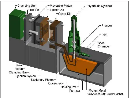
After that, the molten metal flow into plunger, inlet and shot chamber powered by hydraulic pressure. Next the molten metal has been injected into the die through a gooseneck section. By using plunger, functional for compress the molten metal through the shot section into the injected sleeve. While the casting solidifies, the plungers stay the position for holding the pressure. After solidification, clamping unit takes over and the part was ejected while the hydraulic systems retract the plunger. Figure 2.1 show the hot chamber die casting machine.
Figure 2.1: Hot Chamber Die Casting Machine
(Source: <http://www.custompartnet.com/wu/die-casting> 20/02/15)
2.0.2 High Pressure Die Casting
5
Compared with Low Pressure Die Casting (LPDC), HPDC are excellent accuracy in dimensional, have a good finishing and no need machining accept for removal the overflow and runner. Figure 2.2 show the cold chamber die casting machine. HPDC machine size has range between 400 to 4000 tones. Usually HPDC have a few benefits:
Excellent dimensional accuracy Mostly any metal can be cast Have a good finishing Suitable for complex part
Figure 2.2: Cold Chamber Die Casting Machine
6
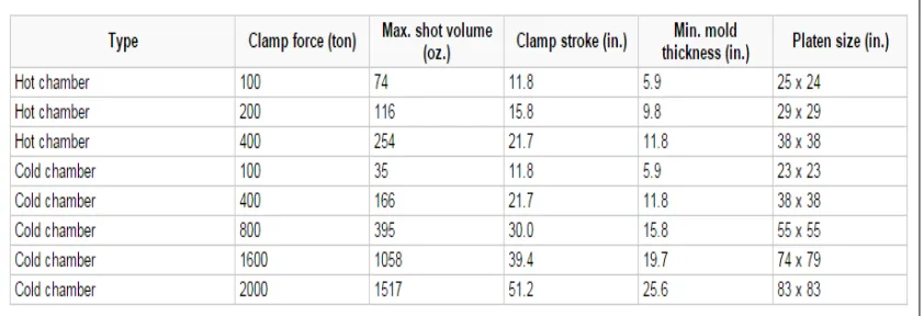
2.0.3 Machine Specification
Hot chamber and cold chamber machine categorized as tons of clamping force. The forces focus at injected area and die area. The bigger part will require more tonnage machines. The size of the part must also comply with other machine specifications, such as maximum shot volume, clamp stroke, minimum mould thickness, and platen size. Table 2.1 shows the machine specification for hot chamber and cold chamber.
Table 2.1: Machine Specification
2.1 Process Cycle
The process cycle for die casting consists of five main stages, which are explained as Figure 2.3.
Figure 2.3: Process Cycle Die Casting
7
2.1.1 Clamping
The first step is the preparation and clamping of the two halves of the die. Each die half is first cleaned from the previous injection and then lubricated to facilitate the ejection of the next part. The lubrication time increases with part size, as well as the number of cavities and side-cores. Also, lubrication may not be required after each cycle, but after 2 or 3 cycles, depending upon the material. After lubrication, the two die halves, which are attached inside the die casting machine, are closed and securely clamped together.
Sufficient force must be applied to the die to keep it securely closed while the metal is injected. The time required to close and clamp the die is dependent upon the machine - larger machines (those with greater clamping forces) will require more time. This time can be estimated from the dry cycle time of the machine.
2.1.2 Injection
8
The amount of metal that is injected into the die is referred to as the shot. The injection time is the time required for the molten metal to fill all of the channels and cavities in the die. This time is very short, typically less than 0.1 seconds, in order to prevent early solidification of any one part of the metal. The proper injection time can be determined by the thermodynamic properties of the material, as well as the wall thickness of the casting. A greater wall thickness will require a longer injection time. In the case where a cold chamber die casting machine is being used, the injection time must also include the time to manually ladle the molten metal into the shot chamber.
2.1.3 Cooling
The molten metal that is injected into the die will begin to cool and solidify once it enters the die cavity. When the entire cavity is filled and the molten metal solidifies, the final shape of the casting is formed. The die can not be opened until the cooling time has elapsed and the casting is solidified. The cooling time can be estimated from several thermodynamic properties of the metal, the maximum wall thickness of the casting, and the complexity of the die. A greater wall thickness will require a longer cooling time. The geometric complexity of the die also requires a longer cooling time because the additional resistance to the flow of heat.
2.1.4 Ejection
9
2.1.5 Trimming
During cooling, the material in the channels of the die will solidify attached to the casting. This excess material, along with any flash that has occurred, must be trimmed from the casting either manually via cutting or sawing, or using a trimming press. The time required to trim the excess material can be estimated from the size of the as cast envelope. The scrap material that results from this trimming is either discarded or can be reused in the die casting process. Recycled material may need to be reconditioned to the proper chemical composition before it can be combined with non-recycled metal and reused in the die casting process.
2.2 Die Design
In addition, die design have a many types of channel. Every single design issues must be considered in the design of the dies. The most important is the design of die must justify to allow the molten metal flow or through easily into all cavity. As known, die casting produce a complex geometry part so the design must be considered for any complex features on the part such as undercuts which will required additional die pieces.