Original Paper
A Methodology for Developing Manufacturing Process Ontologies
Suriati A
KMAL†1,†2and Rafael B
ATRES†1Abstract: The representation of knowledge of manufacturing processes plays a key role in the reuse and sharing of knowledge in areas such as product design and process planning. One common approach for knowledge representation is ontologies. Ontologies are formal models that use mathematical logic to disambiguate and define classes of things . The reasons behind this are twofold. First, ontologies have the ability to be integrated with automated reasoning applications. Second, ontologies are also useful for enabling knowledge sharing between different knowledge -based applications. However, in the absence of systematic methods for their design, most ontologies are developed in an ad-hoc manner. This paper presents a methodology for developing manufacturing process ontologies, which combines formal concept analysis with a set of criteria for characterizing classes of processes. The application of the proposed methodology is ill ustrated with a case study on the development of an ontology for machining processes.
Key words: Manufacturing process, Ontologies, Formal concept analysis, Semantic similarity
1 INTRODUCTION
A manufacturing process aims to fulfill given re-quirements by transforming materials into physical objects with specific shapes, structures and other properties [1]. Several kinds of processes are commonly utilized, includ-ing mass change, phase change, structure change, defor-mation and consolidation processes. A computer represen-tation of manufacturing processes presents a range of po-tential benefits in areas such as product design and process planning [2]-[5]. One approach to the computer represen-tation of processes is by means of ontologies, which cap-ture the semantics of things represented in a specific do-main [6]. Ontologies are useful for knowledge representa-tion and sharing, automated reasoning and human-machine interfaces [7], [8]. In general, a domain ontology is com-posed of classes, relations and axioms [9].A class repre-sents a set of things that share the same attributes. For ex-ample, all the members of the class “drilling” use a drill to remove material and create a hole. A relation is a tuple that indicates a relationship between two or more things. Examples of relations are “less than,”“connected to” and
“part of.” In particular, the subclass relation is defined for organizing classes in the form of a class hierarchy. Axi-oms are typically represented as logical constructions that serve as formal definitions of a given class.
Several ontologies have been developed for generic knowledge representation in the domains of product and manufacturing, including PRONTO [10], MASON [11] and ADACOR [12]. In addition, ontologies have been developed for specific manufacturing processes. For ex-ample, Grüninger and Delaval [13] developed a cutting process ontology that can be used in sheet-metal cutting design.
One of the difficulties in ontology development is the lack of systematic methods for the design of the class hier-archy. This is important because the class hierarchy is a key element in accurate and consistent ontologies [14]. At present, however, it is the current practice to develop class hierarchies in an ad-hoc manner. Another technical chal-lenge is how to define the axioms that constrain the mean-ing of the definitions in the ontology. To address both is-sues, we employ formal concept analysis (FCA) combined with an attribute-selection approach based on the common characteristics of processes. FCA is an analysis technique for knowledge processing that is based on applied lattice and order theory. FCA utilizes a collection of objects and the so-called formal attributes to identify hidden relation-ships. Recently, FCA has been suggested as a tool to de-velop ontologies and is now being used for this purpose in different areas including clinical [15], municipal utility [16], business [17] and product family [18] domains.
This paper is organized as follows. Section 2 reviews current process representations. Section 3 describes the methodology of FCA. Section 4 presents the criteria to select attributes for the FCA. Section 5 describes the
†1Toyohashi University of Technology
†2On leave from Universiti Teknikal Malaysia Melaka
Received: November 30, 2012 Accepted: June 12, 2013
methodology in detail. In section 6, the application of the proposed methodology is illustrated with a case study that describes the development of an ontology for machining processes. An evaluation on the correctness of the ontolo-gy obtained with the proposed methodoloontolo-gy is described in section 7. Finally, in section 8, we state some conclu-sions and directions for future research.
2 PROCESS REPRESENTATION
Several efforts have been made to find a reusable representation of processes. Sowa [19] describes a
process according to time points that mark the
begin-ning and ending of the process and the changes that take place in between. To Sowa, a process can be
caused by one or more agents over some time interval.
Here, an agent is an animate entity that is capable of doing something to fulfill a specific intention.
A process is defined in the SUMO ontology [20]
as “the class of things that happen and have temporal parts or stages.” A process may have participants
which are objects, such as the machine, circuit boards,
components and solder in a soldering process. In SU-MO, an object can denote a physical object or a geo-graphical region. Agent, instrument, resource and re-sult are objects that participate in the process. An
agent is defined as an active determinant (either
ani-mate or inaniani-mate) of the process, with or without voluntary intention. A resource is something that is present at the beginning of a process, is used by the
process, and as a consequence is changed by the
pro-cess. An instrument is used by an agent to perform a
process and is not affected by that process. A resource
differs from an instrument in that its internal or physi-cal properties are altered in some way by the process. A process in IDEFØ [21] is described in terms of
activity building blocks. An activity is characterized
by its inputs, outputs, constraints and mechanisms.
Input is the information, material or energy that is
converted to the output of an activity. An output is the information, material or energy produced by or result-ing from the activity. A constraint or control is the information, material or energy that constrains and regulates an activity. A mechanism represents the re-sources, such as people, equipment or software tools that perform an activity. Furthermore, an activity can be composed of other activities (mereology).
ISO 15926 defines activity as a possible individual
that has its life cycle bounded by beginning and end-ing events [9]. In addition, an activity brings about change by causing an event (an event occurs at an in-stant in time). A participation relation is used to ex-press that a possible individual is involved in an activ-ity. Since ISO 15926 uses a four-dimensional view of the world, an activity consists of temporal parts of those members of possible individuals that participate in the activity. For example, in creating a blind hole on a metal piece using a hand drill, the drilling activity shares the temporal parts of the worker and the hand drill that participates to change the shape of the piece. In this example, the drilling activity causes the hole to come into existence.
WPML is an ontology-based language designed to represent work processes [22]. WPML is based on OntoCAPE [23], which was originally developed as a comprehensive ontology for the chemical process
en-gineering domain. WPML defines an action as a
build-ing block that describes a step in a work process.
Ac-tions are characterized by their causal and temporal
aspects. On the other hand, the changing nature of the
action is described by means of the so-called
Opera-tionalFunction. Therefore, valve_opening, drilling,
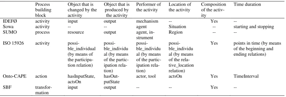
Table 1 Comparison of process representations
Process building block
Object that is changed by the activity
Object that is produced by the activity
Performer of the activity
Location of the activity
Composition of the activ-ity
Time duration
IDEFØ activity input output mechanism -- Yes --
Sowa activity -- -- agent Situation -- starting and stopping SUMO process resource output agent,
in-strument
Region -- --
ISO 15926 activity possi-ble_individual (by means of the participa-tion relaparticipa-tion)
possi-ble_individu al (by means of the partic-ipation rela-tion)
possi-ble_individu al (by means of the partic-ipation rela-tion)
possi-ble_individu al (by means of the rela-tive_location relation)
Yes points in time (by means of the beginning and ending relations)
Onto-CAPE action hasInputState, actsOn
hasOut-putState
actor, tool actsOn Yes TimeInterval
SBF transfor-mation
and material_charging can all be defined as subclasses
of OperationalFunction.
Gero and Kannenngieser [24] propose the use of the structure-behavior-function (SBF) world-view to characterize a process. The notion of a function of a process is related to the goal of providing a given pro-cess, which assumes that processes can be designed. Behavior attributes refer to those attributes of a pro-cess that allow comparison on a performance level. Examples of behavior attributes of processes are speed, rate of convergence, cost, amount of space required and accuracy. The structure of a process is described in terms of its inputs, outputs and subprocesses.
One common denominator in all these approaches is the existence of an elementary element to define the process that is used together with relations that associ-ate the process with other objects. The most common relations are those for identifying the objects that are transformed by the process (the input), those for repre-senting the objects that are produced by the process (the output), those for identifying the tools or the a c-tors that participate in the process, the relations for indicating the location of the process, part-whole rela-tions for describing the process structure, and time duration. Table 1 summarizes these common elements. The methodology proposed in this paper is that these common elements can be used to find similarities (or dif-ferences) among classes of processes. For example, in the process class “vaporization,” the object transformed by this kind of process (input) is a liquid material and the object produced by the process (output) is a vapor material. This characterization clearly differs from that of “ sublima-tion” in which the transformed object is a solid. However, since both classes of processes produce vapor, they are closer related than, for example, a cutting process in which the transformed object and the produced object are both solids. Thus, a list of classes with information of common elements can be used to design a process ontology. In this paper, FCA is used together with this information for the generation of class-hierarchies.
3 FCA
FCA is an analysis technique for knowledge processing based on applied lattice and order theory. FCA can also be used as a tool for the design and maintenance of ontologies, assuming that the ontology developer counts with a list of potential classes [26].
The first step in FCA is to define a set of formal objectsO, a set of formal attributes
A
, and a set ofbinary relations YOA containing all pairs
Y
a
o
,
such that the objecto
O
has the formalattributeaA. For our purposes, the objects represent
potential ontology classes.
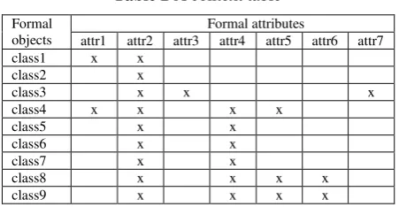
These three sets are typically represented as an incidence matrix referred to as a context table. An example of a context table is shown in Table 2. In a context table, the formal objects are listed in the rows of the first column and the formal attributes in the first row of the table. If a formal object always has an attribute, a checkmark is inserted in that cell, thus defining a binary relation between the object and that particular attribute.
A formal concept is defined as a pair Oi,Aisuch
that:
Oi
O, Ai
A; Every object in Oi has every attribute in Ai. Conversely,
Ai is the set of attributes shared by all the objects in Oi ;
For every object o
O that is not inO
i, thereis an at-tribute in Ai that o does not have; For every attribute in A that is not in Ai, there is an
object in Oi that does not have that attribute.
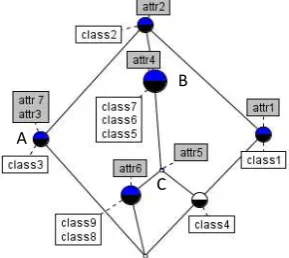
Formal concepts can be partially ordered into a lattice, such that a concept subsumes another concept. Graphically, this means that a node in the lattice represents a formal concept and an edge indicates that a given formal concept is a subconcept of another concept. Each node is labeled with names obtained from the formal objects and formal attributes which are shown in the graph slightly below and above the nodes, respectively.
Several algorithms for generating concept lattices are available some of which have been implemented in public-domain software. Figure 1 shows the concept lattice corresponding to Table 2. In ontology development, each node in the lattice corresponds to a class in the ontology. There are cases in which a
Fig. 1 Example of a concept lattice
A
B
formal concept represents a single class such as class1, class2, class3 and class4. However, this is not always the case. For example, class5, class6, and class7 are redundant and can be represented as a single class (class B) characterized by attributes attr4 and attr2 (inherited from its superclass). It can also be observed that C (class C) represents a class that is characterized by attribute attr5 and is a subclass of class B.
The original formal context is not guaranteed to be complete. Therefore, approaches are needed for improving the lattice. One such approaches is the
so-called object exploration. According to Stumme [26], object exploration is “structured brainstorming” that consists of suggesting implications to the lattice-designer and then evaluating the validity of each implication. If a given implication is found to be incorrect, the lattice-designer determines the attributes that are needed in order to distinguish the conflicting objects. This approach assumes that all objects of the context are given, but the set of attributes is incomplete.
4 CRITERIA FOR ATTRIBUTE SELECTION
Based on the process elements listed in section 2, we propose a set of criteria that can be used for the generation of the identification of formal attributes , which in turn can be used in FCA to generate the class hierarchies of processes.
This is similar to the idea of Gero and Kannenngieser [25] of using their FBS framework for characterizing a process. However, because our main objective is ontology development, we focus on the kinds of objects or constraints that characterize classes of processes rather than focusing on specific instances. In general, a process changes an object that exists before the execution of the process to produce another object. In a four-dimensional view, these objects correspond to the temporal parts of the object before
and after the process. In addition, among the objects that participate in a process, we can distinguish those entities that are not intended to be affected by the activity but that are used by the activity. Therefore, four types of objects that participate in a process can be identified: the objects that are transformed by the process (the inputs), the objects that are produced by the process (the outputs), the objects that are used for the execution of the process (the performers) and the objects that accommodate the process (the location of the process).
For example, a drilling process always transforms a solid object (the so-called blank or workpiece) and produces a solid object that has at least one hole. A
performer in this case is a cutting tool that is pressed against the solid object and rotated in a given way so as to produce the hole. In this example, the location of the process is the machine that holds the cutting tool that is also perpendicular to the workpiece. One can
argue that both the performer and the location may be
affected by the process (e.g., deteriorated) but they are not intended to be modified, which makes them
differ-ent from the other two types of objects. Performer
cor-responds to the concept of instrument in SUMO. It indi-cates an object that is used by the process but that is not intended to be changed by the process.
In addition, a process can be composed of other sub-processes. For example, a given hole-making process can include a cooling sub-process in order to reduce the wear of the cutting tool as a result of friction force.
In summary, we identify five characteristics required for describing a process:
1. Constraints on the class of objects that are always changed by the process
2. Constraints on the class of objects that are always produced by the process
3. Constraints on the class of performers that are always used by the process
4. Constraints on the class of locations that always accommodate the process
5. Constraints on the process composition (the parts of the process)
Based on these five characteristics, the formal attributes of a given class of process can be
identified.1For example, to characterize a fusion
welding process, the objects that are transformed by the activity are solid physical objects. The object
1
Although all activities have time duration, constraints on this element are found at the instance level (such as inscheduling or planning applications) rather than at the class level.
Table 2 A context table
Formal objects
Formal attributes
attr1 attr2 attr3 attr4 attr5 attr6 attr7 class1 x x
class2 x
class3 x x x
class4 x x x x
class5 x x
class6 x x
class7 x x
class8 x x x x
produced by any member of this class of activity is a physical object that is made of the welded parts. As heating is always involved in a fusion welding, it is a part of the activity. Therefore, the attributes of the
welding process become: “transforms solid physical objects,” “produces a physical object” and “composed
of heating.”
Each formal attribute in the FCA context table is seen as a constraint about the meaning of a particular class of process and it is not an attribute in the sense of a property of a specific instance.
5
METHODOLOGY
FOR
DEVELOPING
PROCESS ONTOLOGIES
The proposed methodology aims at facilitating the development of manufacturing-process ontologies in such a way that the ontology developer can justify the
rationale behind the involved decisions. The
methodology consists of the following nine steps:
Step 1 Identification of the purpose and scope of the project.
The purpose and scope are necessary to identify the domain of interest that the ontology will cover ; for example, developing an ontology for machining processes.
Step 2 Identification of the potential classes to be defined under the scope of the project.
This step refers to the identification of potential classes of processes. For example, if the scope was joining processes, the candidate classes would include classes such as soldering, fastening, welding, riveting and brazing. Once the list of classes has been prepared, the ontology developer creates a FCA context table and fills the formal-object column with the classes from the list.
Step 3 Identification of formal attributes.
Each potential class is characterized using the attribute identification criteria described in section 4.
Step 4 Addition of attribute and incidence information to the context table.
Attributes are added to the context table created in step 2. The attributes are listed in the first row of the context table. Subsequently, if a class of process always has a formal attribute, a checkmark is inserted in that cell, thus creating a binary relation between the process class and that particular formal attribute.
Step 5 Use the FCA to generate a concept lattice.
The concept lattice is generated from the context table of step 4. A concept lattice is created by identifying all the formal concepts and subconcepts.
Step 6 Analyze the lattice and resolve inconsistencies. Analysis of the lattice is performed using object exploration [26]. In object exploration, the ontology designer analyzes the consistency of formal objects by tracing all the paths in the lattice. The tracing starts from the root node, then goes to the next lower node and continues until it reaches the bottom node. If the relation between objects in a concept and objects in its subconcept is found to be inconsistent, then the ambiguity must be eliminated by removing or adding attributes.
If the context table is modified then a new concept lattice is generated. This procedure is repeated until all the valid implications between objects have been explored.
Step 7 Create a class hierarchy and convert it into a computer-processable form.
In this step, a class hierarchy is developed based on the lattice obtained in the previous step. The naming of each class is performed after the names of object and attributes that correspond to the concept on which the class is derived. An ontology editor can be used for carrying out this and the remaining steps.
Step 8 Integrate the class hierarchy with an upper ontology.
In this step, the class hierarchy obtained in step 7 is integrated with an upper ontology. Upper ontologies such as ISO 15926 or OntoCAPE can be used. The upper class in the class hierarchy of step 7 is made a subclass of the class that represents processes in the upper ontology. In ISO 15926 this class is activity. As a result, time-related relations such as beginning and ending, as well as mereological relations and participation relations are automatically inherited to the newly created classes of process.
Step 9 Formally define each class by adding axioms, additional classes and relationships.
are added to the ontology until the definitions are complete.
6 CASE STUDY
The purpose of this case study is to evaluate the effectiveness of the proposed methodology. In this case study, we focus on developing an ontology for machining processes.
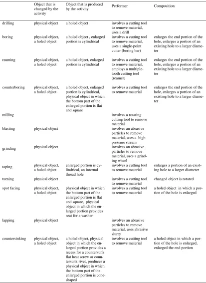
Machining processes are commonly used to remove material and to modify the surfaces of objects that have usually been produced by other means. Several kinds of machining processes exist, including mechanical, electrical, chemical, laser, thermal and hydrodynamic processes [27], [28]. For illustration purposes, the scope of this case study is limited to mechanical machining (i.e., those that use mechanical means to remove material). In order to develop the ontology, several common textbooks [29]-[31] and Internet sources were consulted. The potential classes are listed in the first column of Table 3.
For the preparation of the FCA, attributes were selected based on the flow diagram described in section 4. For example, drilling is a hole-making process that produces a holed physical object using a drill. The object that is transformed by a given instance of drilling is a solid physical object. The object that is produced is also a solid physical object but with a hole in it. Next, constraints on performers and location are identified. For example, a drill is always involved in drilling. Therefore, the formal attributes for drilling are: “changes a physical object,”
“produces a holed object,”“involves a cutting tool to remove material” and “uses a drill.”
Boring, reaming, taping, counterboring, spot facing and countersinking also change a solid physical object and generate a solid physical object with a hole (a holed object). However, these four machining processes differ from drilling in that the workpiece to be machined has already a hole. More differences can be found when we focus on the object that is produced by each of these processes: boring gives place to a physical object with a concentric axis; tapping produces a physical object with a threaded hole; counterboring, spot facing and countersinking produce a physical object in which only a portion of the hole is enlarged. However, in counterboring the enlarged portion is also a hole in which the bottom part is flat
and square. Therefore, the formal attributes of counterboring become: “consumes a physical object,”
“changes a holed object,” “produces a holed object in which a portion of the hole is enlarged,” “enlarges a portion of an existing hole to a larger diameter,”
“produces a holed object with an enlarged portion that
is cylindrical,” “enlarges the end portion of the hole,”
“produces a physical object in which the bottom part
of the enlarged portion is flat and square” and
“involves a cutting tool to remove material.”
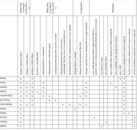
Table 3 summarizes the formal attributes for each potential class. For the location criterion, we could have referred to the machine where a given kind of
process takes place. However, in the mechanical
machining domain, there are different types of machines that range from manual lathes to computer numerical control machines. Since none of the machining processes always take place in a given machine, the corresponding formal attributes are absent (for the same reason the machines are not considered as performers either).
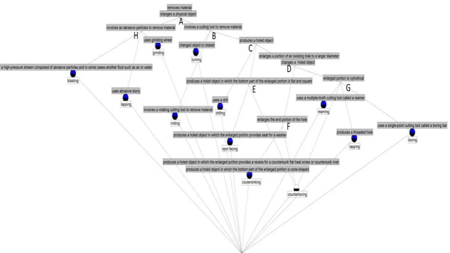
Based on the formal attributes of Table 3, a context table was created (Table 4). Subsequently, Concept
Explorer[32] was used to generate the concept lattice.
The resulting lattice is shown in Fig. 2.
After generating the lattice, object exploration was conducted to verify the completeness of the lattice.
Note there are eight unnamed nodes (A, B, C, D, E, F, G and H) in the lattice. These are considered as newly discovered classes that can be identified based on the individual formal attributes and the parent nodes.
These nodes were named “machining process,”
“machining that uses cutting tool,” “machining that produces a holed object,” “machining that changes a portion of an existing hole to a larger diameter,”
“machining that produces an enlarged portion that is
flat and square,” “machining that enlarges the end
portion of the hole,” “machining that produces an
enlarged portion that is cylindrical,” “machining that uses abrasive particles,” respectively.
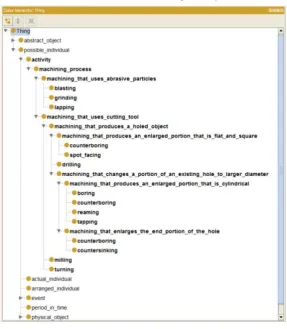
After analyzing and correcting the lattice, the resulting lattice and attribute information served as the basis to develop a computer-processable ontology using the Protégé ontology editor [33]. Protégé has a
graphical user interface that facilitates the
editing the ontology, the user can save the ontologies in the OWL language, which is useful for automatic reasoning and integration. The resulting classes in the ontology are shown in Fig. 3.
The top node of the class hierarchy
(machining_process) was made a subclass of activity in the upper ontology. This paper uses ISO 15926 but
other upper ontologies can also be used
.
Table 3 List of potential classes and formal attributes for machining processes
Object that is changed by the activity
Object that is produced
by the activity Performer Composition
drilling physical object a holed object involves a cutting tool to remove material, uses a drill boring physical object,
a holed object
a holed object , enlarged portion is cylindrical
involves a cutting tool to remove material, uses a single-point cutter (boring bar)
enlarges the end portion of the hole, enlarges a portion of an existing hole to a larger diame-ter
reaming physical object, a holed object
a holed object, enlarged portion is cylindrical
involves a cutting tool to remove material, employs a multiple-tooth cutting tool (reamer)
enlarges the end portion of the hole, enlarges a portion of an existing hole to a larger diame-ter
counterboring physical object, a holed object
a holed object, enlarged portion is cylindrical, physical object in which the bottom part of the enlarged portion is flat and square
involves a cutting tool to remove material
enlarges the end portion of the hole, enlarges a portion of an existing hole to a larger diame-ter
milling involves a rotating
cutting tool to remove material
blasting physical object involves an abrasive particles to remove material, uses a high-pressure stream grinding physical object involves an abrasive
particles to remove material, uses a grind-ing wheel
taping physical object, a holed object
enlarged portion is cy-lindrical, an internal thread hole
involves a cutting tool to remove material
enlarges a portion of an exist-ing hole to a larger diameter
turning physical object involves a cutting tool to remove material
changed object is rotated
spot facing physical object, a holed object
physical object in which the bottom part of the enlarged portion is flat and square, physical object in which the en-larged portion provides seat for a washer
involves a cutting tool to remove material
a holed object in which a por-tion of the hole is enlarged
lapping physical object involves an abrasive particles to remove material, uses abrasive slurry
countersinking physical object, a holed object
a holed object, physical object in which the en-larged portion provides a recess for a countersunk flat heat screw or coun-tersunk rivet, produces a physical object in which the bottom part of the enlarged portion is cone-shaped
involves a cutting tool to remove material
The addition of axioms completes the definition of each class. Depending on the content of the axiom, other classes and relationships may be added. In order to specify more detailed axioms, a geometric representation is needed which is out of the scope of this paper. For example, in counterboring, which
“enlarges a portion of an existing hole to a larger diameter” and “makes the surface at the bottom of the
larger diameter flat and square,” the concentricity of the holes, the relative position of the holes and the characteristics of the surface of the larger hole are some aspects which require a geometric representation.
For convenience, we defined a holed_object as a possible individual that has a hole. Therefore,
holed_object was added to the ontology.
A hole_making process always produces a
holed_object:
(1)
A drilling is a subclass of a hole_making that
involves the use of a drill.
(2)
Table 4 Context table of machining processes
O b je ct t h at is c h an g ed b y t h e ac ti v i-ty O b je ct t h at is p ro d u ce d b y t h e ac ti v i-ty C o m p o si ti o n P er fo rmer ch an g es a p h y si ca l o b je ct ch an g es a h o le d o b je ct p ro d u ce s a h o le d o b je ct p ro d u ce s a th re ad ed h o le en la rg ed p o rt io n i s cy li n d ri ca l en la rg ed p o rt io n i s f la t an d s q u ar e p e n la rg ed p o rt io n p ro v id es s ea t fo r a w ash er en la rg ed p o rt io n p ro v id es a re ce ss f o r a co u n te rs u n k f la t h ea t sc re w o r co u n te rsu n k r iv et th e b o tt o m p ar t o f th e en la rg ed p o rt io n i s c o n e-sh ap ed ch an g ed o b je ct i s ro ta te d en la rg es th e en d p o rt io n o f th e h o le en la rg es a p o rt io n o f an e x is ti n g h o le t o a l ar g er d ia me te r u se s a h ig h -p re ss u re st re am co mp o se d o f ab ra si v e p ar ti cl es a n d i n s o me c ases an o th er f lu id s u ch a s a ir o r w at er u ses a b ra si v e sl u rr y u ses g ri n d in g w h ee l u ses a s in g le -p o in t cu tt in g t o o l ca ll ed a b o ri n g b ar u ses a m u lt ip le -t o o th c u tt in g t o o l (r ea mer) u ses a d ri ll in v o lv es a cu tt in g t o o l to r emo v e ma te ri al in v o lv es a ro ta ti n g c u tt in g t o o l to r em o v e m at er ia l in v o lv es an a b ra si v e p ar ti cl es t o r em o v e mat er ia l
drilling x x x x
boring x x x x x
x
x
reaming x x x x x
x x
tapping x x x x x x
x
counterboring x x x x x x x
x
spot facing x x x x
x
coutersinking x x x x x x x
x
turning x x
x
milling x
x x
blasting x x
x
grinding x x
x
lapping x x
Here, tool_in is defined as a subclass of
participation_of_individual to indicate that something
is involved in an activity that has the role of a tool.
Hole enlarging processes (boring, reaming,
tapping, counterboring, countersinking and spot
facing) consume some possible individual with a hole
and enlarge a portion of that hole.
(3)
The relation part_of is defined as an equivalent
relation of composition_of_individual of ISO 15926.
As pointed by Batres et al. [9], Eq. (3) is a rather simplified axiom . In reality, physical objects and activities must not be defined with physical quantities as attributes. The mapping between a hole and its diameter can be defined as an instance of
class_of_indirect_property, which is defined in ISO
15926. In the OWL version of ISO 15926, the
class_of_indirect_property is implemented as a
subclass of owl:FunctionalProperty, whose domain is
given by members of class_of_individual and whose
range is given by members of property_space.
Therefore, we can define hole_diameter as a relation whose range refers to instances of length. As shown in the following OWL code, length is an instance of
property_space but it is also a class (something valid
in the full version of OWL).
<owl:Class rdf:ID="length">
<rdf:type rdf:resource="&ecm;property_space"/>
</owl:Class>
<owl:FunctionalProperty rdf:ID="hole_diameter">
<rdf:type rdf:resource="&ecm;class_of_indirect_property"/>
<rdfs:domain rdf:resource="#hole"/>
<rdfs:range rdf:resource="#length"/>
</owl:FunctionalProperty>
This has also the advantage that several units of measure can be used. The following is the OWL code for meter.
<owl:ObjectProperty rdf:ID="meter">
<rdf:type rdf:resource="#scale"/>
<rdfs:domain rdf:resource="#length"/>
<rdfs:range rdf:resource="#real"/>
</owl:ObjectProperty>
Fig. 2 Concept lattice of machining processes
A
B
C
D
E
F
For example, a 5 mm diameter can be represented by the following OWL code:
<meter>
<rdf:Description>
<real>
<content>
<xsd:float rdf:value="0.005"/>
</content>
</real>
</rdf:Description>
</meter>
Based on this argument, the axiom for hole enlarging processes becomes:
(4)
The expression
ensures that the comparison between the two holes is carried out with the same unit of measure.
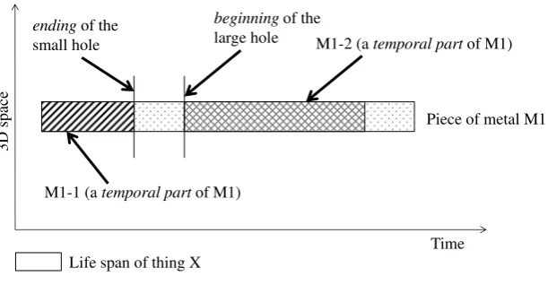
Due to the integration with ISO 15926, all the defined activities in the machining ontology assume a perdurantistic (4D) view of the world, in which activities and physical objects have temporal parts in time and space. For example, let us assume that a specific instance of boring is applied to a metal work -piece M1-1 and produces a machined part M1-2. In this case, M1-1 and M1-2 are temporal parts of a metallic object M1. Figure 4 shows the temporal parts of this boring activity. Here, boring is seen as an activity which ends the existence of M1-1 (the small hole disappears) and produces M1-2 (the larger hole is created). In this case, the ending of M1-1 coincides with the beginning of the boring activity. Similarly, the beginning of M1-2 coincides with the ending the boring activity.
Note that all the machining operations presented so far share one thing in common: the involvement of phenomena such as plastic deformation, frictional forces, thermo-mechanical coupling and chip-and-burr formation [34]. These phenomena are also processes which correspond to parts of each of the machining processes (composition). Should the scope of the project be extended to include advanced machining processes, information about the physico-chemical phenomena will be necessary to emphasize some important differences, such as between turning operation and chemical machining.
7
EVALUATION OF
THE MACHINING
ONTOLOGY AND COMPARISON WITH AN
EXISTING ONTOLOGY
The machining ontology was evaluated and
compared against the manufacturing’s semantics
ontology (MASON) [11]. The purpose of this evaluation was to determine the advantages of the proposed methodology.
Both ontologies distinguish between those
processes based on abrasion and those processes that use a cutting tool (cutting in MASON). These two classes are grouped together as machining_process in our ontology and as Shearing_Operation in MASON. In both ontologies, drilling, milling and turning were grouped under the same class. However, our ontology differentiates between drilling, milling and turning.
A numeric evaluation of the accuracy of each ontology was carried out using semantic similarity measures. For this purpose, in each ontology, we measure the similarity between two classes using the Wu-Palmer similarity measure [35]:
(5)
where N1 and N2 are the number of subclass edges
from C1 and C2 to their closest common ancestor. N3
is the number of subclass edges from the closest common ancestor to the root class in the class hierarchy.
Afterward, for each pair of classes, we compare the value of the Wu-Palmer similarity against the value of the NGD similarity (Eq. 6) which is based on the normalized Google distance [36].
( ) (6)
where f(t1), f(t2) and f(t1, t2) give the number of hits
for the terms t1, t2 and (t1, t2), respectively, each of
which is obtained with a Web search engine. In this evaluation, t1, t2 are terms that correspond to the
names of classes C1 and C2. M corresponds to the
amount of indexed documents in a given Web search engine. For the Web search, we use Google Scholar, for which we assume M=5.8x10⁸ based on an earlier estimate [37] and by assuming a growth rate of 2.7% based on the worldwide average annual increase of academic papers. In addition, search is carried out using double quotes for each keyword and adding "machining" to terms t1 and t2.
The evaluation was carried out by groups of n
classes each of which was compared against it and the remaining n-1 classes. Table 5 shows the result of the first group in the machining ontology, which
corresponds to the pair comparisons for
C1=counterboring. Since there are 12 target classes in
Fig. 4 The temporal part of possible individual for boring activity
endingof the
small hole
beginning of the
large hole M1-2 (a temporal part of M1)
Piece of metal M1
M1-1 (a temporal part of M1)
Time
3D spac
e
the machining ontology (n=12) and 17 target classes in
MASON (n=17), the total number of calculated
similarities were 122 and 172, respectively.
We assess and compare the ontologies by their performance against the NGD similarity, measured using the correlation coefficient (R), the root mean
squared error (RMSE), and the mean absolute
percentage error (MAPE) of each of the pairs (Ci, Cj)
.
Then, the average RMSE of each group was
calculated by summing the individual RMSE for each pair (Ci, Cj) and then dividing the total by n. Also
considered were the minimum and maximum values of
RMSE. Similar calculations were carried out for
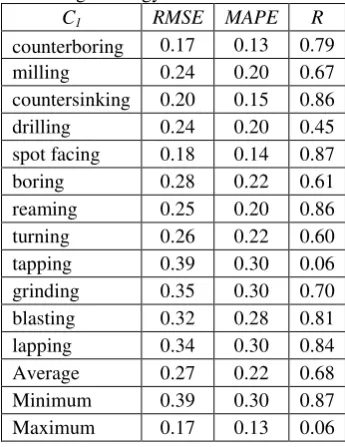
MAPE and R. Table 6 summarizes the results for each class in the machining ontology.
It was noticed that the group that corresponds to the class of tapping (C1=tapping) had a correlation
coefficient of 0.06 which is less than the 1/10 of the average correlation in all the groups. Using a sample of 30 search results obtained with Scholar, we verified that the result was not due to false positives. Therefore, the result suggests that the position of the class in the class hierarchy is inadequate and can be improved.
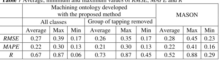
Table 7 shows the average, minimum and maximum values of all groups for both ontologies. The values obtained after removing the group of the class tapping are also included.
Small differences in RMSE and MAPE were found
between both ontologies. However, the correlation coefficient of the machining ontology presented an improvement of 29-40% with respect to that of MASON.
8 CONCLUSIONS
This paper presented a systematic methodology for the ontology development of manufacturing processes. The foundation of the proposed methodology is a combination of FCA and a set of criteria for the selection of formal attributes.
This paper illustrated the proposed approach with the development of an ontology for machining processes. The results showed the benefits of the proposed methodology both in terms of the correctness of the class hierarchy and the documentation of the design rationale of the ontology.
The pairwise comparison of semantic similarities and the NGD similarities served as a mechanism for two purposes: 1) identifying inconsistent classes in the ontology and 2) providing a global score of the accuracy of the ontology.
After the ontology has been developed, the resulting formal attribute information can also serve to document the design rationale of the ontology. In contrast, existing ontology development methods are based on ad-hoc choices which leave little or no explicit reasons behind the decisions made.
Table 5 Evaluation of C1=counterboring using the
class hierarchy of the machining ontology
C2
counterboring 1.00 1.00
milling 0.55 0.50
countersinking 0.86 0.83
drilling 0.61 0.67
spot facing 0.80 0.80
boring 0.69 0.83
reaming 0.77 0.83
turning 0.54 0.67
tapping 0.70 0.83
grinding 0.53 0.25
blasting 0.55 0.25
lapping 0.59 0.25
RMSE 0.17
MAPE 0.13
R 0.79
Table 6 Performance of each class in the machining ontology
C1 RMSE MAPE R
counterboring 0.17 0.13 0.79
milling 0.24 0.20 0.67
countersinking 0.20 0.15 0.86
drilling 0.24 0.20 0.45
spot facing 0.18 0.14 0.87
boring 0.28 0.22 0.61
reaming 0.25 0.20 0.86
turning 0.26 0.22 0.60
tapping 0.39 0.30 0.06
grinding 0.35 0.30 0.70
blasting 0.32 0.28 0.81
lapping 0.34 0.30 0.84
Average 0.27 0.22 0.68
Minimum 0.39 0.30 0.87
Future work is also needed to explore mechanisms for the automatic identification of potential classes and their characteristics. An interesting work in that direction is the approach by Poshyvanyk and Marcus [38] in which automatic formal context generation is part of a scheme to locate information in source code.
ACKNOWLEDGMENTS
We thank the reviewers and the editor for their time and effort, and for their comments that helped to improve the manuscript. The research presented in this paper is supported by Malaysian government scholarship.
REFERENCES
[
1] National Academy of Sciences: UnitManufactur-ing Processes: Issues and Opportunities in
Re-search. The National Academies Press,
http://www.nap.edu/catalog.php?record_id=4827 (1995)
[2] Baxter, D., Roy, R., Doultsinou, A., Gao, J. and
Kalta, M.: “A Knowledge Management Fram
e-work to Support Product-Service Systems,” Int. J.
of Comput. Integr. Manuf., Vol. 22, No. 12, pp.
1073–1088 (2009)
[3] de Sam Lazaro, A. and Engquist, D.T.: “An I ntel-ligent Design for Manufacturability System for Sheet-metal Parts,” Concurrent Eng. Res. Appl.,
Vol. 1, pp. 117–123 (1993)
[4] Soman, A., Padhye, S. and Matthew, I.: “Toward an Automated Approach to the Design of Sheet
Metal Components,” Artif. Intell. Eng. Des., Anal.
Manuf., Vol. 17, No. 3, pp. 187–204 (2003)
[5] Yang, H., Lu, W.F. and Lin, A.C.: “PROCASE: A
Case-based Process Planning System for Machin-ing of Rotational Parts,” J. Intell. Manuf., pp. 411–430 (1994)
[6] Noy, N.F., and McGuinness, D.L.: Ontology De-velopment 101: A Guide to Creating your First
Ontology, Stanford Knowledge Systems
Laborato-ry Technical Report, KSL-01-05 (2001)
[7] Djurić, D., Gaševic, D. and Devedžić, V.: “O
ntol-ogy Modeling and MDA,” J. Object Technol., Vol.
4, No. 1, pp. 109–128 (2005)
[8] Cimiano, P., Hotho, A., Stumme, G. and Tane, J.:
“Conceptual Knowledge Processing with Formal
Concept Analysis and Ontologies,” Proceedings of
the 2nd International Conference on Formal
Con-cept Analysis (ICFCA), pp. 189–207 (2004)
[9] Batres, R., West, M., Leal, D., Price, D., Katsube, M., Shimada, Y., Fuchino, T. and Naka, Y.: “An
Upper Ontology Based on ISO 15926,”Computers
and Chemical Engineering, pp. 519–534 (2007)
[10] Vegetti, M., Henning, G.P., and Leone, H.P.:
“Product Ontology. Definition of an Ontology for
the Complex Product Modeling Domain,” Pro-ceedings of the Mercosur Congress on Process
Systems Engineering (2005)
[11] Lemaignan, S., Siadat, A., Dantan, J.Y. and
Se-menko, A.: “MASON: A Proposal for an
Ontolo-gy of Manufacturing Domain,” IEEE Workshop on Distributed Intelligent Systems: Collective
In-telligence and Its Applications Proceedings, pp.
195–200 (2006)
[12] Borgo, S. and Leitao, P.: “The Role of Founda-tional Ontologies in Manufacturing Domain
Ap-plications,” Lect. Notes Comp. Sci., Vol. 3290,
2004, pp. 670–688 (2004)
[13] Grüninger, M. and Delaval, A.: “A First-order
Cutting Process Ontology for Sheet Metal Parts,”
Proceedings of the conference on Formal
Ontol-ogies Meet Industry, pp. 22–33 (2009)
[14] Haav, H.: “A Semi-automatic Method to
Ontolo-gy Design by using FCA,” Proceedings of the
conference on Concept Lattices and their
Appli-cations (CLA), pp. 13–24 (2006)
[15] Jiang, G., Ogasawara, K., Endoh, A. and Sakurai,
T., “Context-based Ontology Building Support in Clinical Domains using Formal Concept
Analy-sis,” Inter. J. Med. Inf., Vol. 71, No. 1, pp. 71–81 (2003)
[16] Fu, G. and Cohn, A.G.: “Utility Ontology D
evel-opment with Formal Concept Analysis,”
Proceed-ings of the 2008 conference on Formal Ontology
in Information Systems, pp. 297–310 (2006)
[17] Stumme, G.: “Using Ontologies and Formal
Con-cept Analysis for Organizing Business
Table 7 Average, minimum and maximum values of RMSE, MAPE and R
Machining ontology developed
with the proposed method MASON
All classes Group of tapping removed
Average Max Min Average Max Min Average Max Min
RMSE 0.27 0.39 0.17 0.26 0.35 0.17 0.28 0.45 0.23
MAPE 0.22 0.30 0.13 0.21 0.30 0.13 0.22 0.41 0.16
Knowledge,” Referenzmodellierung 2001 (in
print) (2002)
[18] Jyotirmaya, N., Timothy, S., Kumara, S. and
Shooter, S.: “A Methodology for Product Family
Ontology Development using Formal Concept
Analysis and Web Ontology Language,” J. of
Comput. Inf. Sci. Eng., Vol. 6, No. 2, pp. 103–
113 (2006)
[19] Sowa, J.F.: Knowledge Representation: Logical, Philosophical, and Computational Foundations, Brooks/Cole, CA, USA (2000)
[20] Pease, A., Niles, I. and Li, J.: “The Suggested Upper Merged Ontology: A Large Ontology for the Semantic Web and Its Applications,” Working Notes of the AAAI-2002 Workshop on Ontologies
and the Semantic Web (2002)
[21] NIST: Draft Federal Information Processing Standard Publication 183, Dec. 21, 1993, Stand-ard for Integration Definition for Function
Mod-eling (IDEF0).
http://www.itl.nist.gov/fipspubs/idef02.doc, (1993)
[22] Hai, R., Theissen, M. and Marquadt, W.: “An
Ontology Based Approach For Operational
Pro-cess Modeling,” J. Adv. Eng. Inf., pp. 748–759 (2011)
[23] Marquadt, W., Morbach, J., Wiesner, A. and Yang, A.: OntoCAPE: A Re-usable Ontology for Chemical Process Engineering, Springer-Verlag, Berlin (2010)
[25] Gero, J.S. and Kannengiesser, U.: “A Function–
Behavior–Structure Ontology of Processes,” AI
EDAM: Artif. Intell. Eng. Des. Anal. Manuf., Vol.
21, No. 4, pp. 379–391 (2007)
[25] Sowa, J.F.: Building, Sharing, and Merging On-tologies,
http://www.jfsowa.com/ontology/ontoshar.htm (2001)
[26] Stumme, G.: “Exploration Tools in Formal Co
n-cept Analysis,” Ordinal and Symbolic Data Anal-ysis. Studies in Classification, Data Analysis and
Knowledge Organization Proceedings, pp. 1–14
(1995)
[27] Schafrik, R.E.: Unit Manufacturing and Assembly Process (Modern Manufacturing Mechanical
En-gineering Handbook), CRC Press LLC, pp. 13.8–
13.34 (1999)
[28] Kalpakjian, S. and Schmid, S.R.: Manufacturing Engineering and Technology, Prentice-Hall, NJ, USA (2010)
[29] Nagendra Parashar, B.S. and Mittal, R.K.: Ele-ments of Manufacturing Processes, Prentice-Hall of India Private Limited (2007)
[30] Degarmo, E.P., Black, J.T., and Kohser, R.A.:
Materials and Processes in Manufacturing, John
Wiley & Sons, New York, USA (2010)
[31] M. C. Finishing, Blasting Technical Information, http://mcfinishing.com/resources/blastingtech.pdf [32] Yevtushenko, S.: Concept Explorer, Open source
java software,
http://sourceforge.net/projects/conexp, (2009)
[33] Protégé. The Protégé project,
http://protege.stanford.edu
[34] David, J.P., Maranhao, C., Faria, P., Abrao, A., Rubio, J.C. and Silvia, L.R.: “Precision Radial Turning of AISI D2 Steel,” Int. J. Adv. Manuf.
Technol., Vol. 42, pp. 842–849 (2009)
[35] Wu, Z. and Palmer, M.: “Verb Semantic and
Lexical Selection,” Proceedings of the. 32nd An-nual Meeting of the Associations for
Computa-tional Linguistics, Vol. 99, pp. 133–138 (1994)
[36] Cilibrasi, R.L., and Vitanyi, P.M.B.: “The Google
Similarity Distance,” IEEE Trans. Knowledge
Data Eng., Vol. 19, pp. 370–383 (2007)
[37] Giustini, D.: “How Big is Google Scholar? 500
Million Documents?,” http://blogs.ubc.ca/google
scholar/2006/04/how-big-is-google-scholar-500-million-documents/
[38] Poshyvanyk, D. and Marcus, A.: “Combining
Formal Concept Analysis with Information
Re-trieval for Concept Location in Source Code,”
Proceedings of the 15th IEEE International
Con-ference on Program Comprehension, pp. 37–48