Jurnal Teknologi Proses
Media Publikasi Karya Ilmiah Teknik Kimia
6(1) Januari 2007: 59 – 69 ISSN 1412-7814
Finite Element Method Applied on Metal Cutting:
from Chip Formation to Coating Delamination
by Tribo-Energetic Approach
Armansyah Ginting
Department of Mechanical Engineering Faculty of Engineering, University of Sumatera Utara [email protected]
Abstract
Research on finite element methods applied on metal cutting is reviewed. From manufacturing point of view, the implementation of finite element methods for modeling and simulating the process of metal cutting can potentially reduce the number of iterations and result in a substantial cost savings. A general view of machining process evolution from simple analytic models to sophisticated finite element models is depicted. The gist of current research as well as its strategy and the special feature in modeling the metal cutting process are outlined and the future research needs is discussed. In conclusion, the use of finite element methods on metal cutting is limited to modeling the orthogonal cutting, chip formation, distribution of stress, strain, strain-rate, temperature and residual stress with majority assumption that cutting tool is a rigid body.
Keywords: simple analytic models, sophisticated finite element models, orthogonal cutting, chip formation, cutting tool is a rigid body.
Introduction
The process of metal cutting is a series of stages in manufacturing to shape the new work surface by removing the excess stock of material, termed as chip. Although as the excess stock and to be removed; however, knowledge of the process of chip formation is required for understanding the condition of the new work surface [1]. Shortly, chip is the main agent in metal cutting process and its formation mechanism is the essential part that to be considered in studying the mechanics of machining process.
The mechanism of metal cutting process had been studied since the early of 1940s and several models with various degrees of
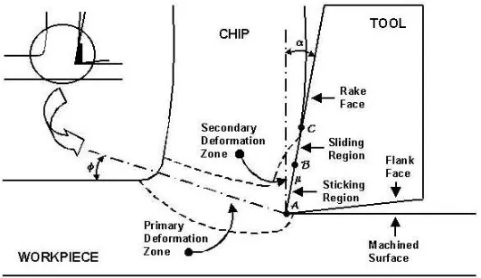
FIGURE 1: The illustration of orthogonal cutting
To account the variation in the flow stress during machining, Palmer and Oxley [6] extend the ideal theory of plasticity by including the effect of work hardening.
Useful contributions in mechanism of metal cutting process have been provided by the former investigations. However, those models are developed based on the over-simplistic assumption and some noteworthy features in metal cutting process, such as the frictional interactions at the tool-chip interface, strain hardening, strain rate sensitivity, and thermal are not yet considered. Recently, with the development of numerical analysis that is the finite element methods and the aid of the computer to provide reliable predictions, the models of metal cutting process have evolved from the simple analytic models to the sophisticated finite element models. The evolution, from manufacturing point of view, has a good impact in production since it can potentially reduce the number of iterations and result in a substantial cost savings.
The purpose of this effort is to review the models of metal cutting process, mainly with the aim of reviewing the model that is developed by utilizing the finite element methods. The current researches as well as the finite element model on metal cutting process are outlined and the future research needs is discussed.
Current Research
It was recorded that the finite element methods had been applied to modeling the machining process since 1970s [7]. In the paper of Okushima and Kakino [7], they make a theoretical analysis on the residual stress in metal cutting based on the mechanical effect of the ploughing force, which exists at the tool edge and the thermal effect of the temperature distribution produced in metal cutting process. They also compare the result of finite element computation with the result of measurement using X-ray diffraction technique and those show a good agreement.
From the recent review on machining process modeling authored by Ehmann et al. [8], generally, the gist of current research in modeling the mechanism of machining process are emphasized on chip formation investigation, distribution of stress, strain, strain-rate, temperature, and residual stress with majority assumption that cutting tool is a rigid body.
[11-13], built-up edge [14, 15] and serrated chip [16], are still limited or even just started.
In metal cutting, a plastically deformed layer is generated on and beneath the machined surface of the work material. Permanent deformations and residual stresses remain in this subsurface layer after machining. The residual stresses have a significant influence on the mechanical behaviours of the cut components. By these reasons, residual stresses become the important thing to be considered besides the investigations of stress, strain and strain rate distributions in the process of metal cutting. As mention previously, Okushima and Kakino [7] were the pioneers in studying this phenomenon by using the finite element methods. Afterwards, in the 1985, Strenkowski and Carroll [17] were studying this subject, followed extensively by Shih et al. [18], Yang et al. [19], Shih [20], and Obikawa et al. [13]. In the extensive study performed by Shih and his associates [18-20], they compared the result that computed by the finite element methods with the result of experiment measured by the X-ray diffraction. The results of comparison between models and experiment show that the distribution of residual stresses shows a good agreement in trend and a certain level of agreement in magnitudes.
In 1983, Stevenson et al. [21] conducted pioneering work in the thermal finite element analysis of metal cutting and followed by the other authors [11, 12, 16, 18-20, 22, 23]. Stevenson et al. [21] compare the direct metallurgical result with the finite element model for the identical tool and workpiece materials and close to the identical cutting condition in calculating temperature distribution in the chip and tool. In fact, the effect of thermal in metal cutting has been taken into consideration by almost of the authors who developing the model of metal cutting process except Zhang and Bagchi [24] but not all of them investigate the temperature distribution of machining in their work.
In metal cutting process, it is well known that tool material much harder than the work material to be machined. Therefore, in developing the machining process model, the tool usually is assumed as a rigid body and
sharp as its ground condition. The assumption is also supported by the mechanical behaviour of materials that the deformation of the tool material in elastic range is much smaller than the deformation in the work material and chip.
To achieve a new invention and to enrich the model of metal cutting process, some authors develop the models with the cutting tool in worn condition. In 1991, Komvopoulos and Erpenbeck [14] claimed that they were the pioneers in studying and developing the effect of the wear cutting tool and built-up edge formation on the model of metal cutting process. In their research, however, the cutting tool was still modeled as a perfectly rigid body. The built-up edge on the tip of cutting tool was assumed as a stationery deposit of a highly work-hardening material and, for simplicity, it was considered as an integral part of the tool. They were also modeling the crater wear on the rake face and it was accomplished by modifying the geometry of the tool according to optical measurement of the crater's dimensions obtained from worn ceramic tools with a zero rake angle. At a later time, Yang and his associates [19] were also modeled the worn tool in their research. In addition, Strenkowski and Athavale [23] develop their model, which can be used to modeling the effect of groove as a chip breaker. They equip their model to simulate metal cutting process by using flat, obstruction and groove cutting tools.
Finite Element Model on Metal Cutting
There are two types of finite element formulations have been utilized by the researchers to model the metal cutting process: namely, Lagrangian and Eulerian formulations. The updated Lagrangian, which develop based on the Lagrangian formulation, is more widely used in modeling of metal cutting. This formulation requires a parting line mechanism and material failure criterion to allow the chip to separate from the workpiece. In a Lagrangian formulation, the finite element mesh is attached to the work material, whereas in an Eulerian formulation, the work material is assumed to flow through a meshed control volume. The Lagrangian formulation is well suited to simulate the entry and exit phases of chip formation as well as intermittent and discontinuous chip formation but those cannot be realized by Eulerian formulation. However, Eulerian formulation eliminates the need for a chip parting criteria or node splitting, avoids mesh distortion, and less expensive in computation by which those occur as the disadvantages of Lagrangian formulation. Lagrangian formulation was used by most of the researchers, except Strenkowski and Moon [22] and Strenkowski and Athavale [23] that prefer to use the Eulerian formulation.
Various chip separation criteria that formulated by parting line mechanism or material failure criterion have been proposed for the finite element methods simulation of metal cutting. In general, these criteria can be divided into two categories: geometrical and physical. Table 1 lists some chip separation criteria, which have been developed in modeling the metal cutting process.
Strenkowski and Carroll [17] were the pioneers on a technique of element separation in front of the cutting tool in order to modeling the chip formation and also the technique of element separation based on the magnitude of the plastic strain. The other techniques of element separation have been proposed by Komvopoulos and Erpenbeck [14], Shih et al. [18], Yang et al. [19], Shih [20], and Zhang and Bagchi [24]. The strategy of parting criteria that established by Zhang and Bagchi [24] was the recent technique in element separation and they claimed that this criterion was equivalent to micro-fracture mechanics. This technique was developed based on the conditional link element between the chip and the workpiece along the predefined separation path. Chip separation from the workpiece is handled with conditional link elements. These 2-node link elements are placed between the chip and the workpiece along a predefined separation path. They make the chip and the workpiece behave as one body before separation occurs (see Fig.2). This separation path is specified along a line parallel to the surface of the workpiece and passing through the tool tip A as shown in Fig.1. The link element consists of two nodes. Since the original length d of the link element is zero, the original coordinates of the two nodes are the same. These link elements have two modes, rigid link and separation, which depend on distance D. Whenever the distance D between the cutting tool edge and the tip of the separation path is equal to or smaller than the predefined value, the conditional link element will be broken and two bodies will be separated at that point. As the cutting tool continuously moves along the workpiece surface, the chip is formed gradually.
TABLE 1: Chip separation criteria
Type of Chip Separation Criteria Researcher(s)
Geometrical Distance
Obikawa et al. [13], Komvopoulos and Erpenbeck [14], Obikawa and Usui [16], Shih et al. [18], Yang et al. [19], Shih
[20], Zhang and Bagchi [24] Stress Iwata et al. [25] Effective Plastic Strain Strenkowski and Caroll [17]
Strenkowski and Moon [22] Physical
Crack Propagation
Marusich and Ortiz [11,12],
FIGURE 2: Illustration of conditional link elements in the finite element model of machining (after Zhang and Bagchi [24])
Instead of using the parting line where the line unzipped when the tool tip is sufficiently close, or when a certain level of plastic strain is attained, Marusich and Ortiz [11,12] and Lei et al. [26] are establishing a new strategy in chip formation process that is fracture model. This model allows the arbitrary crack initiation and propagation in the regime of shear localized chips. The model correctly exhibits the observed transition from continuous to segmented chips with increasing the cutting speed. In the similar objective in modeling the segmented or discontinuous chip, Obikawa et al. [13] and Obikawa and Usui [16] are developed node separation technique. There are two kinds of node separations have been considered to produce discontinuous chips in this technique. One is a node separation at the tool tip because of tool advance and the other is due to crack nucleation and growth during the segmentation of discontinuous chips.
Besides assuming the cutting tool as a perfectly rigid body, the behaviours of workpiece material have been modeled by the researchers as an elastic-plastic model [13, 14, 16-19], a viscoplastic model [22, 23], an elastic-viscoplastic model [19, 20], and a rigid-plastic model [25, 27]. Komvopoulos and Erpenbeck [14] were adding the isotropic strain hardening and strain sensitivity to their model
and Marusich and Ortiz [11, 12] were using a standard formulation of finite deformation plasticity based on multiplicative kinematics, while the true stress-strain curves for 0-3 strain range was chosen by Zhang and Bagchi [24]. In the recent study of modeling the orthogonal machining process, Lei et al. [26] treat the workpiece material as elastic-viscoplastic with isotropic strain hardening, and the numerical solution accounts for coupling between plastic deformation and the temperature field, including treatment of temperature-dependent material properties.
Temperature effect has also been considered in some of the models with the development of the thermo-mechanically coupled algorithm [17-20, 26], such as adopting a staggered procedure where temperature during mechanical step and heat generation during thermal step are assumed constant [11, 12].
continuous remeshing, which has been established by Marusich and Ortiz [11, 12].
Based on the experimental observations, the frictional behaviour along the tool-chip interface leads to the development of sticking and sliding regions [1]. This result has been implemented by some authors [13, 16, 18, 20, 24] in developing the model of metal cutting process with some modifications, such as in the length of sticking and sliding regions, and the selection of friction coefficient whether constant or various.
Future Needs
Many aspects in modeling metal cutting process have been touched. For example, tool has been modeled as a perfectly rigid body whether sharp as its ground condition or worn on its flank face and or rake face. However, it looks like the investigations just in one way direction that is down stream to the central issue in metal cutting process that is chip formation. In contrast, research to the opposite direction, up stream to modeling the tool condition by utilizing the finite element methods, e.g. prediction of tool life during machining process, is still untouched.
Most of the authors use the parting line technique in separating chip from the machined surface. In this case, Zhang and Bagchi [24] are noted as the developer of the latest parting line technique. Unlike that technique, Marusich and Ortiz [11,12], Obikawa et al. [13], Obikawa and Usui [16], and Lei et al. [26] develop the other techniques based on the fracture criterion in both separating chip from the machined surface and the modeling of the segmentation of discontinuous chip. This technique is still a new invention and since 1995, only few researchers [11-13,16,26] utilizing it in modeling the metal cutting process. Due to these facts, only two main techniques have been developed since the first implementation of the finite element
methods on metal cutting in 1970. Thus, new techniques are needed to overcome the leak of both techniques and to achieve the higher acceptable level of simulation results.
From the workpiece material to be cut point of view, Obikawa and Usui [16] develop the model of difficult-to-machine material process that is titanium alloy (Ti-6Al-4V). This work is much different to the other works that usually devote to modeling of machining steel. This work is promising since the machining of titanium alloy is still a problem [28]. By developing the model of cutting this material, the production cost as well as the wide phenomena in titanium machining can be solved. Moreover, this technique can be extended to modeling the other difficult-to-machine materials, such as nickel-based alloy, stainless steel, and graphite.
FIGURE 3: The simulation of serrated chip formation for titanium alloy Ti-6242S produced under dry end milling using coated carbide tool [29]
Research on machining titanium alloy, especially utilizing finite element method to support the research, which is done by Ginting and partners [29-33] in LAMEFIP ENSAM Bordeaux, France is developed into the study on coating delamination. In this study, finite element is utilized in order to simulate the tribo-energetic properties of coated carbide cutting tool when used in dry cutting titanium alloy Ti-64. Shown in Fig. 5 is the result of finite element calculation on conductivity value at the tool nose where coating delamination takes place. Note that in this research, study is no longer focused on chip formation (mostly done by previous researchers) but upstream to the condition of cutting tool (tool wear either on rake and flank faces). The tribo-energetic is a novel method to describe tool wear phenomena in metal cutting. This method is still improved more and more by research collaboration among Ginting in University of Sumatera
Utara, Nouari in ENSAM Bordeaux, El-Mansori in ENSAM Chalons-en-Champagne and Hisham in University of Wisconsin (34-35).
Continuous chip is a significant problem in high-speed automated machinery and in untended machining cells operations using computer numerically controlled machines. This type of chip tends to become entangled and interfere with cutting operations and can become a safety hazard. For this purpose, the cutting tool industry has developed a large variety of cutting insert geometry as well as chip breakers in order to control the chip formation in such a fashion that they can break easily. In this field of study, the attempts have been made to model the groove type chip breaker tools using numerical methods [23,37]; however, the investigation is still limited and further consideration on it is needed.
Finally, the high speed machining should be taken into account. From those papers reviewed, only one paper that is authored by Marusich and Ortiz [12] covers this subject. They develop a model based on the finite element methods to simulate the machining of AISI 4340 steel at velocity of 30 m/s and feed rate of 250µm/rev, with a cutting tool material of tungsten carbide (Fig.3). The fundamental research issues, such as chip formation, cutting temperature, and so on that related to mechanics of machining at high cutting speeds create tremendous challenges to researchers in modeling the metal cutting process.
Conclusion
The following conclusions could be arranged with regard to the review of researches on finite element methods applied on metal cutting.
1. Machining process models have evolved
from the traditional simple analytic models to sophisticated finite element models.
2. Updated Lagrangian and Eulerian
formulations are usually used in developing the model to simulate the metal cutting process.
3. The advantages of finite element methods to study machining process can be seen from the following aspects: (a) material properties can be handled as functions of strain, strain rate and temperature; (b) the interaction between chip and tool can be modeled as sticking and sliding; (c) nonlinear geometric boundaries such as the free surface of the chip can be represented and used; (d) the global variables such as cutting force, feed force, chip geometry, the local stress and temperature distributions can also be obtained.
4. The implementation of finite element
method in modeling the process of metal cutting is limited to orthogonal cutting, chip formation, distribution of stress, strain, strain-rate, temperature and residual stress with majority assumption that cutting tool is a rigid body.
5. Workpiece material generally is treated as elastic-plastic, viscoplastic, elasticviscoplastic, and rigid-plastic finite element model.
6. Parting line for element separation and crack propagation approaches have been established to simulate the chip formation whether for continuous, discontinuous, built-up edge, and serrated chip types.
7. To account the effect of temperature during machining process, a certain procedure called thermo-mechanically coupled algorithm has been developed.
8. The attempts to overcome mesh distortion problems in machining process model have been done, such as by the implementation of mesh rezoning technique and continuous remeshing.
9. The frictional behaviour along the tool-chip interface leads to the development of sticking and sliding regions with some modifications, such as in the length of sticking and sliding regions, and the selection of friction coefficient whether constant or various.
10. There are five main recommendations
counted for future study: (a) utilizing the finite element methods to establish the model for predicting of tool life during metal cutting process; (b) developing the other techniques of chip-workpiece separation besides parting line and crack propagation; (c) developing machining process model for difficult-to-machine materials; (d) modeling of chip breaker as well as insert with groove to overcome a safety hazard in untended machining cells operations using computer numerically controlled machines; (e) developing model of high-speed machining.
References
[1] Trent, E.M. Metal Cutting, Butterworth - Heinemann, Oxford, 1991.
[2] Ernst, H., and Merchant, M.E., “Chip Formation, Friction and High Quality Machined Surface”, Surface Treatment of Metals. Vol.29, pp.229, 1941.
[3] Merchant, M.E., “Basic Mechanics of the Metal Cutting Process”, ASME, J. of App. Mech. Vol.11, pp.A168-A175, 1944.
[5] Lee, E.H., and Schaffer, B.W., “The Theory of Plasticity Applied to a Problem of Machining”,
ASME J. of App. Mech. Vol.18, No.4, pp.405, 1951.
[6] Palmer, W.B., and Oxley P.L.B., “Mechanics of Orthogonal Machining”, Proc. Instn. Mech. Engrs. Vol.173, pp.623-638, 1959.
[7] Okushima, K., and Kakino, Y., “The Residual Stress Produced by Metal Cutting”, Annals of the CIRP. Vol.20, No.1, pp.13-14, 1971. [8] Ehmann, K.F., Kapoor, S.G., DeVor R.E., and
Lazoglu, I., “Machining Process Modeling: A Review”. ASME, J. of Manuf. Sci. and Engg.
Vol. 119, pp.655-663, 1997.
[9] Boothroyd, G., and Knight, W.A.,
Fundamentals of Machining and Machine Tools, 2nd ed., Marcel-Dekker, USA, 1989. [10] Kalpakjian, S. Manufacturing Engineering and
Technology, 3rd ed., Addison-Wesley, USA, 1995.
[11] Marusich, T.D., and Ortiz, M., “Finite Element Simulation of High-Speed Machining”, Simul. of Mat. Process.: Theory, Methods and Appl., Shen and Dawson (eds), Balkema, Rotterdam, pp.101-108. 1995.
[12] Marusich, T.D., and Ortiz, M., “Modelling and Simulation of High-Speed Machining”, Int. J. for Num. Meth. in Engg. Vol.38, pp.3675-3694, 1995.
[13] Obikawa, T., Sasahara, H., Shirakashi, T., and Usui, E., “Application of Computational Machining Method to Discontinuous Chip Formation”, ASME, J. of Manuf. Sci. and Engg. Vol.119, pp.667-674, 1997.
[14] Komvopoulos, K., and Erpenbeck, S.A., “Finite Element Modeling of Orthogonal Metal Cutting”, ASME, J. of Engg. for Ind. Vol.113, pp.253-267, 1991.
[15] Tyan, T., and Yang, W.H., ”Analysis of Orthogonal Metal Cutting Process”, Int. J. for Num. Meth. in Engg. Vol.34, pp.365-389, 1992. [16] Obikawa, T., and Usui, E., “Computational
Machining of Titanium Alloy - Finite Element Modeling and a Few Results”, ASME, J. of Manuf. Sci. and Engg. Vol.118, pp.208-215, 1996.
[17] Strenkowski, J.S., and Carroll, J.T., “A Finite Element Model of Orthogonal Metal Cutting.
ASME, J. of Engg. for Ind. Vol.107, pp.349-354, 1985.
[18] Shih, A.J.M., Chandrasekar, S., and Yang, H.T.Y., “Finite Element Simulation of Metal Cutting Process with Strain-Rate and Temperature Effects”, Proc. Fundamental Issues in Machining, ASME Winter Ann. Meeting, Dallas, TX, Nov. pp.11-24, 1990.
[19] Yang, H.T.Y., Heinstein, M., and Shih, J.M., “Adaptive 2D Finite Element Simulation of Metal Forming Processes”, Int. J. for Num. Meth. in Engg. Vol.36, pp.1487-1507, 1993. [20] Shih, A.J., “Finite Element Simulation of
Orthogonal Metal Cutting”, ASME, J. of Engg. for Ind. Vol.117, pp.84-93, 1995.
[21] Stevenson, M.G., Wright, P.K., and Chow, J.G., “Further Developments in Applying the Finite Element Method to the Calculation of Temperature Distributions in Machining and Comparisons With Experiment”, ASME, J. of Engg. for Ind. Vol.105, pp.149-154, 1983. [22] Strenkowski, J.S., and Moon, K.J., “Finite
Element Prediction of Chip Geometry and Tool/Work-piece Temperature Distributions in Orthogonal Metal Cutting”, ASME, J. of Engg. for Ind. Vol.112, pp.313-318, 1990.
[23] Strenkowski, J.S., & Athavale, S.M. 1997. A Partially Constrained Eulerian Orthogonal Cutting Model for Chip Control Tools. ASME, J. of Manuf. Sci. and Engg. Vol.119, pp.681-688, 1997.
[24] Zhang, B., and Bagchi, A., “Finite Element Simulation of Chip Formation and Comparison with Machining Experiment”, ASME, J. of Engg. for Ind. Vol.116, pp.289-297, 1994. [25] Iwata, K., Osakada, K., and Terasaka, Y.,
“Process Modeling of Orthogonal Cutting by the Rigid-Plastic Finite Element Method”, J. of Engg. Mater. And Technol. Vol.106, pp.132-138, 1984.
[26] Lei, S., Shin, Y.C., and Incropera, F.P., “Thermo-Mechanical Modeling of Orthogonal Machining Process by Finite Element Analysis”, J. of Mach. Tools & Manuf. Vol.39, pp.731-750, 1999.
[27] Mori, K., hand-out of subject on Advanced Materials Processing, Toyohashi University of Technology, Japan, 1998 (in Japanese).
[28] Ginting, A., and Che Haron, C.H., “Pemesinan Bahan Angkasa Lepas – Aloi Titanium: Satu Ulasan”, Proc. of. the 1st Colloquium of Dept. Mechanical & Materials Engg, National Univ. of Malaysia, Muhamad, N., Abdullah, S., Muchtar, A., and Arifin, A. (eds.), pp.182-187, 1999 (in Malaysian).
[29] Ginting, A. and Nouari, M. 2006. Experimental and numerical studies on the performance of alloyed carbide tool in dry milling of aerospace material. International Journal of Machine Tools & Manufacture 46 (7-8): 758 – 768 [30] Nouari, M. and Ginting A., 2006. Wear
[31] Calamaz, M., Noauri, M. and Ginting, A. 2005. Mecanisme d’usure des outils de coupe en usinage a sec de l’alliage aeronautique TA6V.
Proceeding of the 17eme Congres Francais de Mecanique, Troyes, France, Septembre 2005 [32] Calamaz, M., Nouari, M. and Ginting, A. 2006.
Feasibility of the dry machining process on the aeronautic titanium alloys. Proceeding of the 5th Int. Conference of High Speed Machining,
Metz, France, 14-16 March 2006
[33] Nouari, M., Ginting, A. and Calamaz, M. 2005. Catastrophic failure of straight tungsten carbide when orthogonally dry machining titanium alloy Ti-64. Proceeding of the 15th International Conference on Wear of Materials, San Diego, US
[34] Nouari, M., Abdeel-Aal, H.M., El-Mansori, M. and Ginting, A. 2006. Study on machining characteristic of aeronautical material under orthogonal dry cutting. Accepted in International Journal of Machine Tools & Manufacture
[35] Abdeel-Aal, H.M., Nouari, M., El-Mansori, M. and Ginting, A. 2006. Conceptual tribo-energetic analysis of cutting tool protective coating delamination in dry cutting of hard-to-cut engine alloys. Submitted to Int. J. Adv. Manuf. Technol
[36] Nouari, M., Ginting, A. and Abdeel-Aal, H.A. 2006. On tribo-energetic perspective to study the effect of tool-chip adhesion in the failure mode of carbide tool when orthogonally dry cutting aeronautical material. Submitted in J. of Wear.
[37] Athavale, S.M., and Strenkowski, J.S., “Material Damage-Based Model for Predicting Chip-Breakability”, ASME, J. of Manuf. Sci. and Engg. Vol.119, pp.675-680, 1997.
![FIGURE 2: Illustration of conditional link elements in the finite element model of machining (after Zhang and Bagchi [24])](https://thumb-ap.123doks.com/thumbv2/123dok/371079.34823/5.595.164.419.90.291/figure-illustration-conditional-elements-finite-element-machining-bagchi.webp)
![FIGURE 3: The simulation of serrated chip formation for titanium alloy Ti-6242S produced under dry end milling using coated carbide tool [29]](https://thumb-ap.123doks.com/thumbv2/123dok/371079.34823/7.595.180.423.468.728/figure-simulation-serrated-formation-titanium-produced-milling-carbide.webp)
![FIGURE 5: The continuous chip formation (after Marusich and Ortiz [12]).](https://thumb-ap.123doks.com/thumbv2/123dok/371079.34823/8.595.199.394.371.711/figure-continuous-chip-formation-marusich-ortiz.webp)
