UNIVERSITI TEKNIKAL MALAYSIA MELAKA
CO
2Laser Etch Drilling of Mild Steel
Thesis submitted in accordance with the requirements of the Universiti Teknikal Malaysia Melaka for the Degree of Bachelor of Engineering
(Honours) Manufacturing (Design)
By
Mohamad Nabil Fikri B Abdul Rahim
UTeM Library (Pind.1/2005) UTeM Library (Pind.1/2005)
UNIVERSITI TEKNIKAL MALAYSIA MELAKA (UTeM)
BORANG PENGESAHAN STATUS TESIS*
JUDUL: CO2 LASER ETCH DRILLING OF MILD STEEL
SESI PENGAJIAN: 2007/2008
Saya MOHAMAD NABIL FIKRI B ABDUL RAHIM
mengaku membenarkan tesis (PSM/Sarjana/Doktor Falsafah) ini disimpan di Perpustakaan Universiti Teknikal Malaysia Melaka (UTeM) dengan syarat-syarat kegunaan seperti berikut:
1. Tesis adalah hak milik Universiti Teknikal Malaysia Melaka.
2. Perpustakaan Universiti Teknikal Malaysia Melaka dibenarkan membuat salinan untuk tujuan pengajian sahaja.
3. Perpustakaan dibenarkan membuat salinan tesis ini sebagai bahan pertukaran antara institusi pengajian tinggi. atau kepentingan Malaysia yang termaktub di dalam AKTA RAHSIA RASMI 1972)
(Mengandungi maklumat TERHAD yang telah ditentukan oleh organisasi/badan di mana penyelidikan dijalankan)
(TANDATANGAN PENULIS) Alamat Tetap:
No 328, Lot 4986, Taman Matang, Jaya, Jln Matang, 93050, Kuching, Sarawak
DECLARATION
I hereby, declare this thesis entitled “CO2 Laser Etch Drilling of Mild Steel” is the
result of my own research except as cited in the references.
Signature : ...
Author’s Name : MOHAMAD NABIL FIKRI B. ABDUL RAHIM
APPROVAL
This thesis to the senate of UTem and has been accepted as partial fulfillment of the requirements for the degree of Bachelor of Manufacturing Engineering (Design
Manufacturing). The members of the supervisory committee are as follow
Dr.Bagas Wardono
ABSTRACT
This paper presented an investigation on width line based on the etching process on CO2
ABSTRAK
Tesis ini mendedahkan kajian ke atas ukuran lebar berdasarkan kepada proses goresan dengan mengunakan CO2 mesin laser. Parameter yang digunakan dalam kajian ini adalah
DEDICATION
For my beloved Father and Mother who always encourage me and give all the supports
iv
ACKNOWLEDGEMENTS
I wish to acknowledge and express my gratitude and appreciation to (i) my supervisor, Dr. Bagas Wardono for his supervision, encouragement, suggestion and assistance through the research; (ii) my parents, Mr. Abdul Rahim B. Abdul Karim and Madam Saadiah @ Sa’diah Bt. Bujang; (iii) my beloved brother, Muhammad Izzul Na’imullah B. Abdul Rahim; (iv) my beloved one’s, Siti Najihah Bt. Hj Bohari for their constant encouragement, faith and confidence besides continuously moral support.
TABLE OF CONTENT
List of Abbreviations, Symbols and Specialized Nomenclature ...xiv
1. INTRODUCTION ...1
2.1 Fundamental Principal of Laser...4
2.6.1 Cutting Speed...18
2.8.1 Pulsed Laser Materials Processing, ND-YAG versus CO2, Lasers……....22
3. METHODOLOGY ...27
3.9 Engraving Process on Laser Machine HELIUS 2513...33
3.10 Analysis on Cutting Tool and Work Material...34
4. RESULT AND DISCUSSION...37
4.1 Width and Depth of Cut Based on Microscope Axioscope Figure...37
4.2 Qualitative Analysis...37
4.2.1 Images of Width...37
4.2.2 Design of Experiment (DOE) ...40
4.3 Significant Parameter Evaluation...41
4.3.1 Pareto Chart of Standardized Effect...41
4.3.2 Normal Probability Plot of the Standardized Effect...42
4.3.4 Interaction Plot (data means)...44
4.3.5 Contour Plot...46
4.3.6 Surface Plot...49
4.4 Interpretation of Main Effect Plot for Width...50
5. CONCLUSION AND RECOMMENDATION...52
5.1 Conclusion...52
5.2 Recommendation...53
REFERENCES ...54
APPENDICES
A Visual and metallographic observation
LIST OF FIGURES
2.1 Energy states of Laser Active Medium...4
2.2 CO2 laser Machine...8
2.3 Atoms transition efficiently from their broad absorption bands...9
2.4 Apparatus for Nd: YAG Laser...10
2.5 Universal Beam………...15
2.6 Laser Etching on Camshaft Gear...16
2.7 CO2 laser Beam Cutting...18
2.8 Focusing Lens...19
2.9 Different setup of Focusing Lens...19
2.10 Parameter Concerning Gas Pressure...20
2.11 Diagram of Width...21
2.12 SEM-photo of laser drilled hole in ceramic shaft...25
3.1 Engraving on the workpiece...34
3.2 Flow Chart...35
4.9 Pareto Chart of Standardized Effect for Width...41
4.10 Normal Probability Plot of the Standardized Effect for Width...42
4.11 Residual Plots for Width...43
4.13 Laser cutting assisted with gas pressure...45
4.14 Contour Plot of Width vs. Speed, Power...46
4.15 Contour Plot of Width vs. Gas Pressure, Power...47
4.16 Contour Plot of Width vs. Gas Pressure, Speed...48
4.17 Surface Plot of Width vs. Gas Pressure, Speed...49
4.18 Surface Plot of Width vs. Gas Pressure, Power...49
4.19 Surface Plot of Width vs. Speed, Power...50
LIST OF TABLES
2.1 Properties of Nd: YAG...12
2.2 Mechanical data for Carbon Steels 43A...17
2.3 Composition Data for Carbon Steels 43A ………...17
2.4 Physical Data for Carbon Steels 43A...17
3.1 Control Factor...30
3.2 Gantt chart...36
4.1 Fixed Variables and Dynamic Variables...40
LIST OF ABBREVIATIONS, SYMBOLS, SPECIALIZED
NOMENCLATURE
CO2 - Carbon Dioxide
Nd: YAG - Neodymium-Doped Yttrium Aluminium Garnet
KW - Kilowatts
Ra - Roughness Average @ Arithmetic Average
In - Inch
Cu - Cubic
CW - Continuous Mode
Ms - Millisecond
SEM - Scanning Electron Microscope
(Ra) - Average Surface Roughness
(Xs) - Factor
(Y) - Output
1
CHAPTER 1
INTRODUCTION
1.1 Background
The micro-machining manufacturing for use in the electronic and mechanical devices is a well-established industry. Early process of technology relied on the production of micro-components from semiconductors and thin metal films through the use of large batch production techniques that were originally developed especially for the use in the micro-electronics industry purposes. Nowadays, laser micromachining had rapidly become a routine method in fabricating mass produced parts, as well as manufacturing intricately designed components for specialized applications.
Laser micromachining is now a commonplace in the component of manufacturing sector, for instance supplying industries that demand on high precision dimension such as aerospace, automotive, biomedical, and electronics industries. Laser micro-machining is used to produce a very small parts or very small features in parts. It is more or less similar to cutting and drilling method, but on a very small scale. Components which are small as a few microns can be manufactured by using a very high peak power short pulses and low average power. The resolution of the features produced is proportional to the wavelength used and the beam quality.
2
used as components for micro-systems. Two process methods commonly used for the fabrication of high aspect-ratio micro-structures are based on direct micro-machining with a frequency CO2 (carbon dioxide) laser and Nd: YAG (neodymium-doped yttrium
aluminium garnet) laser using nanosecond pulse widths. CO2 lasers are an excellent
alternative to the traditional methods of engraving or marking metal process. CO2 laser
marking has substantial advantages against Nd: YAG laser marking in terms of speed, and the cost of maintenance. Etching or marking metal with CO2 lasers provides many
advantages over etching, engraving, and marking with contact implements like scribers or manual laser laden process like electro chemical etching [1].
1.2 Problem Statements
This research will focus on a study about micromachining using CO2 laser machine in
order to analyze the width of etching using different setup of parameters. In particular, the study will evaluate the influencing machining parameters such as cutting speed, power and gas pressure to the surface finish.
1.3 Objectives of the Research
There are several objectives that will be achieved in this study. Those include: a) To conduct a literature study on CO2 micro machining process.
b) To assess the parameters affecting the CO2 micro machining process.
c) To analyze the mechanism, behavior and characteristic of CO2 laser machine.
d) To design an experiment in order to determine the significant of the parameters. e) To analyze the outcome of laser applications on the surface material Grade 43A of
3
1.4 Scope
The focus of the study is on the CO2 laser characteristic and properties. The study will be
4
CHAPTER 2
LITERATURE REVIEW
2.1 Fundamental Principle of Laser
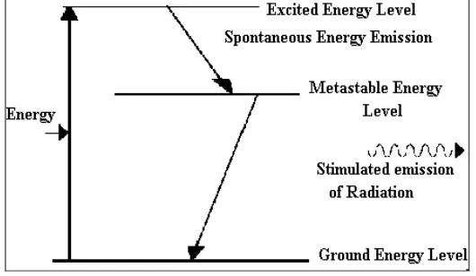
Figure 2.1: Energy states of Laser Active Medium
The term laser is an acronym for Light Amplification by Stimulated Emission of Radiation which is a device that emits light through a specific mechanism [2]. A typical
laser emits light in a narrow, low-divergence beam and with a well-defined wavelength corresponding to a particular color if the laser is operating in the visible spectrum [3].
5
such that light bounces back and forth, each time passing through the gain medium. One of the two mirrors, the output coupler, is partially transparent. The output laser beam is emitted through this mirror. The gain medium transfers external energy into the laser beam. The gain medium is energized, or pumped, by an external energy source.
The pump energy is absorbed by the laser medium, placing some of its particles into high-energy quantum states. When energy is applied to a laser active medium (Fig. 2.1) electrons are raised to an unstable energy level then spontaneously decay to a lower relatively long-lived metastable state. Electrons in this state will not spontaneously return to their ground energy level; therefore it is possible to pump large amounts of energy into the material thus obtaining a population inversion in which most of the atoms are in a metastable state. If the phenomenon can be multiplied, we arrive to the fact that the percentage of atoms with high energy levels will be superior to the percentage of atoms in normal state [4]. This phenomenon is known as population inversion. Devices where light from an external source is amplified are normally called optical amplifiers [5].
After this population inversion has been achieved, lasing action is initiated by an electron which spontaneously returns to its ground state producing a photon. If the photon released is of exactly the right wavelength it will stimulate an atom in a metastable state to emit a photon of the same wavelength (Stimulated Emission).
6
When the beam strikes the totally reflecting mirror in the optical cavity the beam is reversed and continues to stimulate emissions of photons which increase in intensity until the beam reaches the partially reflecting surface of the optical cavity. A small portion of the coherent light is released while the rest is reflected back through the lasing medium to continue the process of stimulating photons. Laser radiation will continue to be produced as long as energy is applied to the lasing medium.
2.2 CO2 (Carbon Dioxide) Laser
Nowadays, laser has revolutionized to modern, easy handling, automatic and can be used for various applications. Laser also widely used in many diverse micro-system technology sectors such as automotive, manufacturing, medicine and others. The requirement and demand of products has led the development and refinement in the laser system and laser applications [6].
There are many types of lasers in the manufacturing process. It depends on the materials that will be used in the manufacturing process in selecting a suitable type of laser machine. CO2 laser have long been used in manufacturing and medical applications. The
CO2 laser was one of the earliest gas lasers to be developed. It was invented by Kumar
Patel of Bell Labs in 1964, and is still one of the most useful. CO2 lasers are the
highest-power continuous wave lasers that are currently available. They are also quite efficient in terms of the ratio of output power to pump power, which can be as large as 20%. Most of the CO2 lasers are rated in Watts or Kilowatts. A huge CO2 laser machine which is used
in the metalworking manufacturing has output power up to 30kW. The CO2 can emit a
beam of infrared light with principal wavelength centering around 9.4 and 10.6 micrometers. In industry, the CO2 laser is used in many forms of welding, cutting
7
environment, it is used to analyze the chemical composition of the upper atmosphere, which aids in weather prediction [7].
The most common used of CO2 laser is in material processing. Low power CO2 laser can
serve to cut, mark or drill through plastic, rubber, ceramic and glass. They can also be
CO2 lasers are very useful for engraving metal, etching, laser marking, Laser etching of
metals with CO2 lasers can be accomplished several different ways:
1. CO2 laser marking and laser etchings of metal with lower powered CO2 laser and
additives.
2. CO2 laser marking and laser etching of metal at with higher powered CO2 without
additives.
3. CO2 laser marking and laser etching of metal that is painted, coated or anodized.
Current research in CO2 laser cutting involves the use of very high beam quality lasers
(capable of being focused to small spots of high power density) for high speed cutting of thin metals (over 140m/min for 0.25mm thick material). On the other hand, research is developing techniques to increase the thickness of material that can be cut. In this respect steel up to 60mm thick has been cut with moderate (< 5kW) laser power. Commercial development of CO2 laser cutting systems involves the use of special focusing lenses,
8
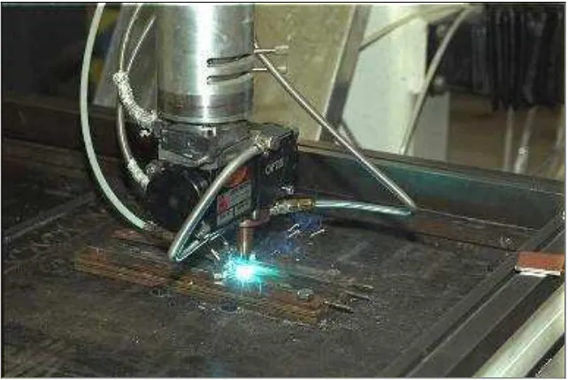
Figure 2.2: CO2 laser Machine
CO2 laser is generally used for contour cutting and deep penetration welding. The long
wavelength of CO2 light, 10.6um, is absorbed by most solids. This allows CO2 lasers to
process a wide variety of materials. There are several advantages using CO2 Laser Beam
Cutting:
Low heat input to the work piece, hence low distortion or warping of the cut components
Very thin (as thin as 0.025mm / .001") and flexible materials can be cut without distortion
Cut edges are relatively smooth and approximately perpendicular to the surface and frequently need no further shaping or cleaning prior to further fabrication
Because of narrow kerf width and heat-affected zones, patterns can be closely nested, resulting in material savings The process is easily automated and can be interfaced other automatic equipment
There is no tool wear as in cutting with a saw milling tool or punch press
Difficult-to-cut materials, including very soft material, such as foam rubber, and very hard material, such as ceramics, can be cut
Composites can be cut without tearing of edges