SUPERVISORS’S DECLARATION
"I hereby declare that I have read this thesis and this work is sufficient in terms of concept and quality for the award of a Bachelor of Mechanical Engineering
(Thermal-Fluid)"
Signature : ...
i
COMPARISON ON THE MICROSTRUCTURE AND HARDNESS OF SMA WELDING AND GMA WELDING OF DUAL PHASE STEEL
LINUS MICHAEL S/O STEPHEN MIRANDO
This report is submitted as
fulfillment of the requirements for the award Bachelor of Mechanical Engineering (Thermal-Fluid)
Faculty of Mechanical Engineering Technical University of Malaysia Melaka
ii
STUDENT DECLARATION
"I declare that this report is the result of my own work except for the summary and every passage I only have a clear source and references "
Signature : ...
iii
ACKNOWLEDGEMENT
iv
ABSTRACT
v
ABSTRAK
vi
TABLE OF CONTENT
CHAPTER SUBJECT PAGE
TITLE i
DECLARATION ii
ACKNOWLEDGEMENTS iii
ABSTRACT iv
ABSTRAK v
TABLE OF CONTENT vi
LIST OF TABLES x
LIST OF FIGURES xi
CHAPTER 1 INTRODUCTION 1
1.1 Background Of Study 1
1.2 Objective 2
1.3 Scope 3
1.4 Problem Statement 4
1.5 Method Used To Achieve Objective 4
CHAPTER 2 LITERATURE REVIEW 6
2.1 Introduction 6
2.2 Steel Definition 9
vii
2.2.2 Types Of Carbon Steels 13
2.3 Mild Steel 14
2.4 Dual Phase Steel 15
2.5 Application 19
2.6 Welding 20
2.6.1 ARC (SMAW) Welding 24 2.6.2 MIG (GMAW) Welding 26 2.6.3 MIG Welding Equipment 28 2.6.3.1 Welding Gun And Supply Unit 28 2.6.3.2 Welding Gun Types 29 2.6.3.3 Power Supply 30
2.6.3.4 Electrode 30
2.6.3.5 Shielding Gas 31 2.7 Microstructure Analysis 34 2.8 Mechanical Testing 36 2.8.1 Rockwell Hardness Test 36 2.8.2 Tensile Testing 39
CHAPTER 3 METHODOLOGY 43
3.1 Introduction 43
3.2 Sample Specification 44
3.2.1 Cutting 44
3.2.2 Squaring 45
3.2.3 Beveling 46
3.2.4 Heat Treatment 46
3.2.5 Welding Process 48
3.2.6 Mounting 49
3.2.7 Grinding 50
viii
3.4 Microstructure Analysis 52 3.5 Mechanical Testing 53
CHAPTER 4 RESULTS AND DISCUSSION 55
4.1 Introduction 55
4.2 Experimental Results 55 4.2.1 Hardness Test 55
4.2.1.1 GMA Welding 56 4.2.1.2 SMA Welding 58 4.2.2 Microstructure Analysis 59 4.2.2.1 Base Metal (Dual Phase Steel) 59 4.2.2.2 GMA Welding 60 4.2.2.2.1 Welding Zone 60 4.2.2.2.2 Heat Affected Zone 60 4.2.2.3 SMA Welding 61 4.2.2.3.1 Welding Zone 61 4.2.2.3.2 Heat Affected Zone 61
4.3 Discussion 62
4.3.1 Hardness Test Result Analysis 62 4.3.2 Microstructure Result Analysis 63
CHAPTER 5 CONCLUSION AND RECOMMENDATION 66
5.1 Conclusion 66
ix
x
LIST OF TABLES
NO. TITLE PAGE
2.1 The Most Common Arc Welding Processes 26 2.2 Rockwell scale with different type of indenter and loads 37 2.3 Rockwell hardness scale with different type of application 38
3.1 Welding parameters 47
4.1 Hardness Test Scale For GMA welding 55
4.2 Hardness Test Scale For SMA welding 56
xi
LIST OF FIGURES
NO. TITLE PAGE
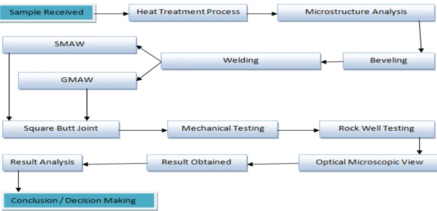
1.1 Project Development Flow Chart 3
2.1 Iron Carbon Phase Diagram 12
2.2 Production Of Dual Phase Steel By Annealing 17
2.3 Auto Body Structure Steel Grade Distribution 20
2.4 Basic Welding Circuit Of Smaw 25
2.5 Basic Mig Welding Process 34
2.6 Optical Microscopy View 35
2.7 Rockwell Hardness Test Principle 37
2.8 Standard Tensile Test Specimen 39
2.9 Stress-Strain Diagram For Mild Steel 40
2.10 Tensile Test Equipment 41
3.1 Specimen For Microstructure View 43
3.2 Milling Machine 44
3.3 V Groove Beveling 45
3.4 Heat Treatment Oven 46
3.5 Automatic Mounting Press 48
3.6 Sand Paper Grade 400 49
3.7 Sand Paper Grade 600 49
3.8 Sand Paper Grade 1000 49
3.9 Sand Paper Grade 1200 49
3.10 Polishing Machine 50
3.11 Specimen Polishing 50
xii
3.13 Optical Microscope 51
3.14 Rockwell Tester 52
3.15 120° Spherical Diamond Cone Indenter 52
4.1 Hardness Test Surface 55
4.2 Gmaw Rockwell Scale Graph Vs Distance 56
4.3 Smaw Rockwell Scale Graph Vs Distance 56
4.4 100x Magnification(Dps) 57
4.5 200x Magnification(Dps) 57
4.6 500x Magnification(Dps) 57
4.7 1000x Magnification(Dps) 57
4.8 50x Magnification(Gmaw) 58
4.9 100x Magnification(Gmaw) 58
4.10 200x Magnification(Gmaw) 58
4.11 200x Magnification(Smaw) 59
4.12 50x Magnification(Smaw) 59
4.13 500x Magnification(Smaw) 59
4.14 Gmaw And Smaw Rockwell Scale Graph Vs Distance 60
4.15 Dual phase steel microstructure 63
4.16 GMA welding overall microstructure view 63
4.17 SMA welding overall microstructure view 64
4.18 GMAW 65
1
CHAPTER ONE
INTRODUCTION
1.1 BACKGROUND OF STUDY
The reason of this research is to make comparisons between MIG and ARC welding on microstructure characterization and hardness using dual phase steel between MIG (GMAW) welding and ARC (SMAW) welding. As mentioned, material used in this research is dual phase steel. Dual phase steel is a high strength steel that has a ferrite and martensitic microstructure. DPA starts as low or medium carbon steel quenched from a temperature above 700°C but below 750°C on an uninterrupted cooling alteration diagram.
2
There are three steps of heat treatment which were annealing, quenching, and tempering. Investigation has to be performed to examine reaction and manners under GMA welding and SMA welding of the materials. This investigation emphasizes the significance of evaluation with welding joining technique. About the GMAW weld it can also be classify as subtypes metal inert gas (MIG) welding or metal active gas (MAG) welding, is a semi automatic or automatic arc welding process in which a uninterrupted and fragile wire electrode and a shielding gas are supplied through a welding gun.
A steady voltage, direct current power source is usually used with GMAW, but direct current systems, as well as alternating current, can be used. There are four main methods of metal move in GMAW, called globular, short-circuiting, spray, and pulsed-spray whereby each of them has different belongings and equivalent pros and restraints. [1] For the ARC (SMAW) weld it can be described as type of welding that utilizes a welding power to provide an electric arc between an electrode and the base material to melt the metals at the welding position.
They can either choose direct (DC) or alternating (AC) current, and consumable or non-consumable electrodes. The welding section is mostly shielded by some type of shielding gas, vapors, and slag.[2] Finally about the heat treatment process, it can be assume as heat treatment where a material is altered, causing changes in its properties such as strength and hardness. It is a process that produces conditions by heating to above the recrystallization temperature, maintaining a suitable temperature, and then cooling.[6]
1.2 OBJECTIVE OF STUDY
3
mechanical properties and microstructure of a weld joint using GMAW and SMAW. Finally is to investigate the effect of welding types on the microstructures of GMA and SMA welding.
1.3 SCOPE OF STUDY
[image:16.612.119.560.374.587.2]This research begins with literature survey and conducts laboratory work on the microstructure characterization and hardness of GMA and SMA welding. Other than that research begins with literature review on heat treatment to produce dual phase steel. Welding analysis involves the optical microscope to obtain various views of the microstructure observation of dual phase steel. Lastly would be mechanical test which relates conducting hardness test to evaluate the mechanical properties result and to analyze. The project development process is shown below in Figure 1.1.
4
1.4 PROBLEM STATEMENT
Recently, welding is the most popular joint in engineering application due to the low operation cost. Improper welding technique and parameter errors may cause a failure on welding joints. From previous study, a lot of researchers study on the failure analysis of spot welding and stir welding. Least of research’s done on the failure analysis or the optimum parameters for the MIG and ARC welding joint. The welding joint is the weakest point in a component because most of the component failures occur on the welding joints.[7]
These problems might be due to the weld porosity, excessive heating, lack of fusion and inclusion during the welding process. Therefore, failure analysis on MIG and ARC welding will be done in this study to understand the behavior of the joining on dual phase steel. The optimum parameter for the welding joints will also be identified.[8] The results of welding joint to be study are hot cracking, microstructure differences, and mechanical.
1.5 METHOD USED TO ACHIEVE OBJECTIVES
This research presents an experimental study on precipitation hardening of MIG(GMAW) weld and ARC(SMAW) weld to determine the effect of artificial ageing on the effect of strength (brittle or ductile). The precipitation hardening usually undergoes a thermal treatment, which consist of solution heat treatment (732 °c for 40 minutes), quenching in water, at room temperature and artificial ageing. The material then will be beveled using the lathe machine at 30°. After undergoing the bevel process, the next proceeding step would be the weld process where the material will be weld accordingly to MIG (GMAW) and ARC (SMAW) weld.
5
6
CHAPTER 2
LITERATURE REVIEW
2.1 INTRODUCTION
This chapter intended to review the literature of the most two high productivity welding which were ARC(SMAW) and MIG(GMAW) welding in terms of microstructure view and mechanical testing which was hardness test on dual phase steel forms one of the main reasons for this study. In the previous study, research or journalism due to dual phase steel characterized by good cold-forming properties and suitable as pressed and welding parts.[9] Supremely, in this study dual phase steel is the stuff where the welding will labor on.
This is due to its small yield ratio for a very soaring tensile strength. The steel is characterized by fine cold forming property and appropriate for welded parts, particularly for ARC and MIG welding. Special advantages of this steel are the so called work-hardening and bake-hardening properties. Work hardening is enhancing in strength caused by the forming process. As a result of bake hardening, the strength also increases during heat treatment. These method leads to elevated strength and excellent fatigue strength in the finished component.[10]
7
with precise processing conditions. Additionally, a low carbon matter concentration is required to coincide with the two phase austenite-ferrite region of the Fe-C phase diagram. At higher temperature, the steel is compiled of ferrite and austenite, but upon cooling, the austenite convert to martensite and the dual phase ferrite martensite microstructure is achieved.
This transformation causes high dislocation density in ferrite near martensite ferrite interfaces and high residual stresses.[11] Because of the difficult microstructures and mechanisms involved, dual phase steels are the best to have continuous elastic behavior (i.e., no defined yield point), high hardening rate, low yield force, and high ultimate tensile strength.[12] Dual-phase steels also advantage from their composite microstructure in that that martensite imparts strength while ferrite imparts elasticity.[13]
The mechanical goods of dual phase steels and their microelements are also reliant on iron phase chemistry, thermal progression, mass, internal stresses, and impulsive content.[12] The mechanical goods of dual-phase steels may be refrained by regulating the volume portions of the micro constituents. Many instigators have studied the result of increasing of martensite element on the mechanical character and have found that strength increases linearly with developing martensite volume fraction accurate with the rule of mixtures.[10,14]
By predictable composite strengthening, as the portion of the harder phase, in this case, the martensite is raised, the strength of the composite also risen. Somewhat conflicting results have been noted in which the strength of the composite rise linearly up to a martensite volume portion after which the strength gradually declined.[15] This characterization was obtained to a decline in power of the martensite effecting from lower carbon concentration in martensite at higher martensite volume fraction.
8
martensite continuity have also been seen to manipulate the power of the steel, and thus period fraction is not the micro structural determinant for mechanical manners.[15,16,17] The method of thermal treating is often done to adjust the mechanical manners of ferrite and/or martensitic steels. Basically, martensite includes steels, strength generally declined while elasticity increases with growing thermal contact caused by tempering martensite.
During this process, carbon diffuses out of the martensite and the tetragonal distortion of the phase is reduced, resulting in decreased residual stresses and strength of the steel composite.[18,19,20] In thermal contact firstly, the steel is heated to a high temperature such that dispersion of the alloying elements occurs and a supersaturated solution is formed. Second, the steel is quenched and then heated to suitable temperatures at which the supersaturated solution decomposes and precipitates are formed that may impede dislocation motion and strengthen the material.[21]
A balance of strength and ductility may thus be achieved through precipitation hardening and tempering of martensite, respectively. One of the challenges in quantifies the composite behavior of dual phase steels is the of examining the properties of the solo martensite and ferrite micro constituents in dual-phase steels. Earlier studies have used Nano indentation to survey the mechanical properties of the steels’ micro constituents to better understand the composite behavior. This technique is particularly precious in dual-phase steels because of the capability of indenting individual segments.
9
dual phase steel and the effects of thermal aging and precipitation hardening on the evolution of mechanical properties will be observe.
2.2 STEEL DEFINITION
Steel is an alloy that has mostly of iron and carbon contents between 0.2% and 2.1% by weight, rely on the grade. Carbon is the most ordinary alloying matter for iron, but diverse to the alloying elements used, such as manganese, chromium, vanadium, and tungsten. Carbon and other elements work as a hardening element, avoiding dislocations in the iron atom crystal lattice from moving past one another.
Varying the quantity of alloying elements and the form of their occurrence in the steel (solute components, precipitated segments) directs behaviors such as the hardness, ductility, and tensile strength of the resulting steel. Steel with boosted carbon content can be ready harder and stronger than iron, but such steel is also less ductile than iron. Alloys with a higher than 2.1% carbon elements are known as cast iron because of their minor melting point and good cast capability.[27]
Steel is also noticeable from wrought iron, which can contain a few amount of carbon, but it is integrated in the form of slag inclusions. Two distinguishing factors are steel's raised rust confrontation and better weld ability. Though steel had been formed by various ineffective methods long before the Renaissance, its use became wider after more-efficient creation methods were developed in the 17th century. With the creation of the Bessemer process in the mid-19th century, steel became cheap mass-produced material.
10
appliances, and weapons. Modern steel is generally known by various ranks defined by assorted standards personnel’s.
2.2.1 Steel Material Properties
Iron is initiated in the Earth's layer only in the shape of an ore, i.e., united with other elements such as oxygen or sulphur.[28] Usually iron-containing minerals consist of Fe2O3 the shape of iron oxide found as the mineral hematite, and FeS2 pyrite (fool's gold).[29] Iron is removed from ore by removing oxygen and merging the ore with a preferred chemical partner such as carbon. This process, known as smelting, was first concerned to metals with lower melting degrees, such as tin, which melts at 250 °C and copper, which melts at approximately 1,100 °C. In difference, cast iron melts at 1,375 °C.
All of these temperatures could be achieved with ancient techniques that have been exploited since the Bronze Age. Since the oxidation tempo itself increases swiftly beyond 800 °C, it is significant that smelting take place in low-oxygen surroundings. Unlike copper and tin, liquid iron liquefies carbon quite readily. Smelting results in an alloy (pig iron) having too much carbon to be called steel.[30] Other materials are often included to the iron/carbon mixture to fabricate steel with desired belongings. Nickel and manganese in steel include to its tensile strength and make austenite more chemically even, chromium increases hardness and melting temperature, and vanadium also increases hardness while the effects of metal fatigue is losing.
11
processing.[31] The density of steel differs based on the alloying elements but normally ranges between 7,750 and 8,050 kg/m3), or 7.75 and 8.05 g/cm3.[32]
Even in the small range of focus which make up steel, combinations of carbon and iron can shape a number of dissimilar structures, with very different belongings. Recognizing such properties is vital to making quality steel. At room temperature, the most even form of iron is the body centered cubic (BCC) constitution α-ferrite. It is a ideally soft metallic material that can break up only a small concentration of carbon, not more than 0.021 wt% at 723 °C, and only 0.005% at 0 °C.
If steel have more than 0.021% carbon at steel producing temperatures then it converts into a face-centered cubic (FCC) builds, called austenite or γ-iron. It is also soft and metallic but can melt considerably more carbon, as much as 2.1% carbon at 1,148 °C, which reveals the upper carbon content of steel.[33,34] Martensite has a lower density than austenite does, so that conversion between them, findings in a change of volume. In this case, extension occurs. Internal stresses from this extension generally take the form of solidity on the crystals of martensite and tension on the remaining ferrite, with a correct amount of shear on both elements.