SUPERVISOR’S DECLARATION
I have read this thesis and in my opinion this thesis coincides with the scope and the quality to be awarded Bachelors Degree in Mechanical Engineering (Automotive).
Signature : ……….
Supervisor‘s Name : Cik Nor Liana Binti Salleh
i
THE INVESTIGATION OF THE INFLUENCE OF FILLER WELDING MATERIALS ON THE MICROSTRUCTURE AND HARDNESS OF GTA
WELDING IN DUAL PHASE STEEL
AJAY NAIR A/L RAVINDRAN NAIR
This report was submitted in accordance with the partial requirements for honor of Bachelor of Mechanical Engineering (Automotive)
Faculty of Mechanical Engineering Universiti Teknikal Malaysia Melaka
ii
DECLARATION
“I hereby declare that the work in this report is my own except for summaries and quotations which have been duly acknowledged.”
Signature: ...
iv
ACKNOWLEDGEMENTS
In name of GOD I would like to express my first and foremost gratitude for giving me the optimum health, courage and strength along the period of completing this project.
It gives me the greatest pleasure to express my sincere and heartfelt thanks to my supervisor, Cik Nor Liana Binti Salleh of which we had an excellent working relationship, and who offered tremendous help and encouragement throughout the course of my graduate studies and completion of this project.
My sincere thanks also to my friends, all technicians and staffs in Faculty of Mechanical, UTeM; thank you for the co-operations, helps, and patience.
Thanks also to Universiti Teknikal Malaysia Melaka for giving me the opportunity to complete my degree program successfully.
I would also like to take this opportunity to thank my family members who inspired and supported me throughout the completion of my project.
v
ABSTRACT
vi
ABSTRAK
vii
TABLE OF CONTENT
CHAPTER SUBJECT PAGE
TITLE i
DECLARATION ii
ABSTRACT v
TABLE OF CONTENT vii
LIST OF TABLE xi
LIST OF FIGURES xii
CHAPTER 1 INTRODUCTION 1
1.1 Introduction 1
1.2 Problem Statement 2
1.3 Objective 3
1.4 Scope 4
CHAPTER 2 LITERATURE REVIEW 5
2.1 Introduction 5
viii
2.2.1.1 Limitations of plain carbon steel ` 7 2.2.2 Dual phase steel 7
2.3 Welding Process 9
2.3.1 GTA welding 11
2.3.2 Filler material 13 2.4 Mechanical Testing 14
2.4.1 Hardness Test 14
2.5 Microstructure Analysis 16 2.5.1 Optical Microscopy 17
CHAPTER 3 METHODOLOGY 18
3.1 Introduction 18
3.2 Methodology 18
3.3 Sample Specification 20
3.3.1 Sample Dimension 20 3.3.2 Type of material 21 3.3.3 Material Composition 21
3.4 Sample Preparation 22
3.4.1 Cutting 22
3.4.2 Squaring 23
3.4.3 Beveling 24
3.4.4 Heat Treatment 24
3.4.5 Welding Process 24
3.4.6 Grinding 25
3.4.7 Mounting 25
3.4.8 Polishing 26
3.5 Microstructure Analysis 28
ix
3.6.1 Hardness Test 29
3.6.1.1 Rockwell Hardness Test 30 CHAPTER 4 RESULTS AND DISCUSSION 32
4.1 Introduction 32
4.2 Experimental Results
4.2.1 Hardness testing 32 4.2.1.1 Filler Material Type SS7018 33 4.2.1.2 Filler Material Type SS6013 34 4.2.1.3 Filler Material Type SS308L 35 4.2.2 Microstructure Analysis 36
4.2.2.1 Filler Material Type SS7018 36 4.2.2.1.1 Dual Phase Steel 36 4.2.2.1.2 Welding Zone 37 4.2.2.1.3 Heat Affected Zone 37 4.2.2.2 Filler Material Type SS6013 38 4.2.2.2.1 Dual Phase Steel 38 4.2.2.2.2 Welding Zone 39 4.2.2.2.3 Heat Affected Zone 39 4.2.2.3 Filler Material Type SS308L 40 4.2.2.3.1 Dual Phase Steel 40 4.2.2.3.2 Welding Zone 41 4.2.2.3.3 Heat Affected Zone 41
4.3 Discussion 42
CHAPTER 5 CONCLUSION AND RECOMMENDATION 44
x
5.2 Recommendation 46
REFERENCES 47
APPENDIX 50
xi
LIST OF TABLES
NO. TITLE PAGE
3.1 Chemical composition of base metal 0.19 wt %C 21
3.2 Properties of 1018 Mild Steel 21
3.3 Welding Filler Materials and parameters 24
4.1 Table of hardness results for Filler SS 7018 33
4.2 Table of hardness results for Filler SS 6013 34
xii
LIST OF FIGURES
NO. TITLE PAGE
2.1 Iron-iron Carbide Phase Diagram 8
2.2 Master Chart for welding and allied processes 11
2.3 Optical Microscope 17
3.1 Sample dimension 20
3.2 Sample after cutting 22
3.3 Milling Machine used for Squaring 23
3.4 Mounting Machine 26
3.5 Sandpaper Hand Grinder 27
3.6 Rotating Grinder 27
3.7 Optical Microscope 28
3.8 Hardness Testing Machine 30
4.1 Front view of the welding region and the points of
indentation for hardness test 33 4.2 Graph of Hardness against distance for Filler 7018 33 4.3 Graph of Hardness against distance for Filler 6013 34 4.4 Graph of Hardness against distance for Filler 308L 35
4.5 Magnification at 50x 36
4.6 Magnification at 100x 36
4.7 Magnification at 200x 36
4.8 Magnification at 500x 36
xiii
4.10 Magnification at 100x 37
4.11 Magnification at 200x 37
4.12 Magnification at 500x 37
4.13 Magnification at 50x 37
4.14 Magnification at 100x 37
4.15 Magnification at 50x 38
4.16 Magnification at 100x 38
4.17 Magnification at 200x 38
4.18 Magnification at 500x 38
4.19 Magnification at 50x 39
4.20 Magnification at 100x 39
4.21 Magnification at 200x 39
4.22 Magnification at 500x 39
4.23 Magnification at 50x 39
4.24 Magnification at 100x 39
4.25 Magnification at 50x 40
4.26 Magnification at 100x 40
4.27 Magnification at 200x 40
4.28 Magnification at 500x 40
4.29 Magnification at 50x 41
4.30 Magnification at 100x 41
4.31 Magnification at 200x 41
4.32 Magnification at 500x 41
4.33 Magnification at 50x 41
4.34 Magnification at 100x 41
4.35 Graph of comparison between filler rods
SS6013, SS 7018 and SS 308L 42
4.36 HAZ of SS 7018 43
4.37 HAZ of SS 6013 43
1
CHAPTER 1
INTRODUCTION
1.1 Background of Study
This chapter describes the background study of how the filler welding materials influence the microstructure and hardness of TIG welding in dual phase steel. Tungsten inert gas (TIG) or more commonly known as Gas Tungsten Arc Welding (GTAW) according to ASME standards was originally known as Heliarc welding. It was invented by Russell Meredith who was an engineer working for Northrup Aircraft during World War II. The first paper on the process appeared in the Welding Journal in 1941. Meredith was awarded three patents on the process, the first of which was Patent No. 413,711, issued on February 24, 1942. The objective had been to develop a process to weld magnesium without the use of flux. On June 15, 1942, Meredith was presented with the prestigious Award of Merit by Frank Knox, Secretary of the Navy [1].
2
In this study, dual phase steel is used as the base metal. Dual phase steel is one of the more common advanced steels and is widely used in industries. This material is mainly used to create complicated and strong metal parts. The composition of the dual phase steel is mainly branched into two phases that is ferrite and martensite. Dual phase steel can be categorized by the advantages of each phase and how it complements each other. Starting with ferrite, ferrite has a chromium content of 16-20% with a corrosion resistance better than martensitic steel but inferior to austenitic steel. Ferrite steel is highly ductile but are subjected to brittle failure at low temperatures. They have moderate strength and limited weldability and are hardenable but heat treatment. Due to the low carbon content, it is very suitable for forming without cracking. Besides that, ferrite steel are magnetic and have low coefficients of thermal expansions. Martensite has a chromium content which is 12-18% and a nickel content which is 1-3%. These types of steel are the least corrosion resistant of all. They are unsuitable for welding or cold forming. They have moderate machineability and are used where high resistance to tempering at high temperature is important. Nevertheless, they can be heat treated to improve their properties and can be produced with a wide range of properties [3].
3
austenite region. Further increasing the volume fraction of martensite increases the strength of the dual phase material. Unfortunately, increasing the martensite content might reduce ductility and toughness [5].
Based on a study done by Aendraa Azhar Abdul Aziz, it is concluded that different filler materials used will affect the tensile stress and the tensile elongation of the material. By studying the hardness and microstructure of the welded joints of the dual phase steel, the influence of filler welding material can be investigated [6].
1.2 Problem Statement
GTA welding is suitable for both manual and mechanized welding. However, the hardness of the weld is questionable based on the filler material used. Different filler material causes various defects in the weldment. This is due to the mechanical properties of the filler metal itself. By using dissimilar filler metals, we can determine the influence of filler metals on the weldment and contemplate the best filler that should be used for GTA welding by studying the mechanical properties (hardness) and microstructure of the welded joints [7].
1.3 Objective
The investigation of the influence of filler welding materials on the microstructure and hardness of GTA welding in dual phase steel.
1. To study the microstructure characterization and hardness of GTA welding with dissimilar filler welding material.
2. To identify the influence of various filler materials and its defects in a weldment.
4
1.4 Scope
Following statements are the scopes of project:
1. The study involves butt joints as the welding type and dual phase steel as the base metal.
2. To investigate the influence of filler welding materials on the hardness of the weld.
3. Vickers Hardness Test is used to determine the hardness of the welded joints based on the dissimilar filler material used.
5
Chapter 2
LITERATURE REVIEW
2.1 INTRODUCTION
In this chapter, the review of pass journals is done. When doing a literature review, you systematically examine all sources and describe and justify what you have done. This enables someone else to reproduce your methods and to determine objectively whether to accept the results of the review. For this research, Ferrite-Austenite Dual-Phase steel is used. This type of DP steel relates to a high strength, low-alloy, having an improved combination of formability and high product steel. This is the reason this steel is chosen for research [8].
2.2 STEEL
6
interstices between iron atoms and the carbon goes into solid solution of iron. As carbon dissolves in the interstices, it distorts the original crystal lattice of iron. This mechanical distortion of crystal lattice interferes with the external applied strain to the crystal lattice, by mechanically blocking the dislocation of the crystal lattices. In other words, they provide mechanical strength. Obviously adding more and more carbon to iron (up to solubility of iron) results in more and more distortion of the crystal lattices and hence provides increased mechanical strength. However, solubility of more carbon influences negatively with another important property of iron called the ‘ductility’ (ability of iron to undergo large plastic deformation). The a-iron or ferrite is very soft and it flows plastically. Hence we see that when more carbon is added, enhanced mechanical strength is obtained, but ductility is reduced. Increase in carbon content is not the only way, and certainly not the desirable way to get increased strength of steels. More amount of carbon causes problems during the welding process [10].
2.2.1 Mild Steel
7
i. Low carbon steel or mild steel, containing carbon up to 0.25%. It responds to heat treatment as improvement in the ductility is concerned but has no effect in respect of its strength properties.
ii. Medium carbon steels, having carbon content ranging from 0.25 to 0.70% improves in the machinability by heat treatment. It must also be noted that this steel is especially adaptable for machining or forging and where surface hardness is desirable.
2.2.1.1 Limitations of plain carbon steel.
Like everything, the plain carbon steels do have some appreciable properties but also consists of some limitations. These are:
i. There cannot be strengthening beyond about 100000 psi without significant loss in toughness (impact resistance) and ductility.
ii. Large sections cannot be made with a martensite structure throughout, and thus are not deep hardenable.
iii. Rapid quench rates are necessary for full hardening in medium-carbon leads to shape distortion and cracking of heat-treated steels.
iv. Plain-carbon steels have poor impact resistance at low temperatures.
v. Plain-carbon steels have poor corrosion resistance for engineering problems. vi. Plain-carbon steel oxidises readily at elevated temperatures [11]
2.2.2 Dual Phase Steel
8
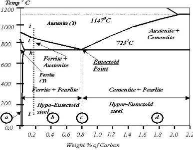
distributed within. In conventional dual phase steel, the second phase is martensite although austenite or bainite may also be present, in which case the steel may include more than the two iron metallurgical phases that the name implies. Dual phased steel is used, for example, in cold-formed sheet steel articles. The composite microstructure produces an advantageous combination of mechanical properties that allow the steel to be readily formed, but to develop a high-formed strength. The iron-carbon equilibrium diagram is a plot of transformation of iron with respect to carbon content and temperature. This diagram is also called iron-iron carbon-phase diagram and is shown in Figure 2.1 below.
Figure 2.1 Iron-iron carbon phase diagram
9
Ferrite (α): Virtually pure iron with body centered cubic crystal structure (bcc). It is stable at all temperatures upto 9100C. The carbon solubility in ferrite depends upon the temperature; the maximum being 0.02% at 723oC.
Cementite: Iron carbide (Fe3C), a compound iron and carbon containing 6.67% carbon by weight.
Pearlite: A fine mixture of ferrite and cementite arranged in lamellar form. It is stable at all temperatures below 723oC.
Austenite (γ): Austenite is a face centred cubic structure (fcc). It is stable at temperatures above 723oC depending upon carbon content. It can dissolve upto 2% carbon.
The maximum solubility of carbon in the form of Fe3C in iron is 6.67%. Addition of carbon to iron beyond this percentage would result in formation of free carbon or graphite in iron. At 6.67% of carbon, iron transforms completely into cementite or Fe3C (Iron Carbide). Generally carbon content in structural steels is in the range of 0.12- 0.25%. Upto 2% carbon, we get a structure of ferrite + pearlite or pearlite + cementite depending upon whether carbon content is less than 0.8% or beyond 0.8%. Beyond 2% carbon in iron, brittle cast iron is formed [12].
2.3 WELDING
10
mistakes that otherwise would occur through trial. The primary differences between the various welding processes are the methods by which heat is generated to melt the metal. The most common types of welding are oxyfuel gas welding(OFW), arc welding(AW), and resistance welding(RW). Welding current is the most influential variable in arc welding process which controls the electrode burn off rate, the depth of fusion and geometry of the weldments. Welding voltage is the electrical potential difference between the tip of the welding wire and the surface of the molten weld pool. It determines the shape of the fusion zone and weld reinforcement. High welding voltage produces wider, flatter and less deeply penetrating welds than low welding voltages. Depth of penetration is maximum at optimum arc voltage. Welding speed is defined as the rate of travel of the electrode along the seam or the rate of the travel of the work under the electrode along the seam. Some general statements can be made regarding speed of travel. Increasing the speed of travel and maintaining constant arc voltage and current will reduce the width of bead and also increase penetration until an optimum speed is reached at which penetration will be maximum. Increasing the speed beyond this optimum will result in decreasing penetration. In the arc welding process increase in welding speed causes:
i. Decrease in the heat input per unit length of the weld. ii. Decrease in the electrode burn off rate.
iii. Decrease in the weld reinforcement.
11
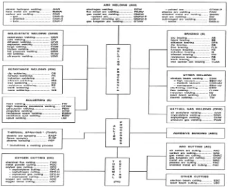
Figure 2.2 Master Chart for welding and allied processes
(Source: http://www.guthriejags.net/ag/welding/Introduction%20to%20Welding.pdf)
2.3.1 Gas Tungsten Arc Welding (GTAW)