FEASIBILITY STUDY OF THE DESIGN OF ARTIFICIAL DISC REPLACEMENT PROSTHESES
YUSRA LIYANA BINTI JAAFAR
ii
SUPERVISOR DECLARATION
“I hereby declare that I have read this thesis and in my opinion this report is sufficient in terms of scope and quality for the award of the degree of Bachelor of
Mechanical Engineering (Structure and Materials)”
iii
FEASIBILITY STUDY OF THE DESIGN OF ARTIFICIAL DISC REPLACEMENT PROSTHESES
YUSRA LIYANA BINTI JAAFAR
This report submitted in partial fulfillment of the requirements for Degree of Bachelor in Mechanical Engineering (Structure and Materials)
Faculty of Mechanical Engineering Universiti Teknikal Malaysia Melaka
iv
DECLARATION
“I hereby declare that the work in this report is my own except for summaries and quotations which have been duly acknowledged”
ACKNOWLEDGEMENT
First of all, I praise to almighty, Allah SWT, for having made everything possible by giving me strength and courage to do this Final Year Project. I also take this opportunity to express my profound gratitude and deep regards to my supervisor Dr Mohd Juzaila bin Abd Latif for his vital encouragement, monitoring and guidance throughout this project.
vi
ABSTRACT
vii
ABSTRAK
viii
CONTENTS
ACKNOWLEDGEMENT v
ABSTRACT vi
ABSTRAK vii
CONTENTS viii
LIST OF FIGURES x
LIST OF TABLES xii
LIST OF APPENDIX xiii
NOMENCLATURE xiv
ABBREVIATIONS xv
CHAPTER 1 INTRODUCTION 1.1 Overview
1.2 Problem Statement 1.3 Objective
1.4 Scope
1 1 2 2 2 CHAPTER 2 LITERATURE REVIEW
2.1 Structural Anatomy of Human Spine 2.2 Intervertebral Disc
2.3 Spine-related disease and LBP 2.4 Disc Degenerative Disease 2.5 Facet Joint Degenerations
2.6 Conventional Treatment of Low Back Pain 2.7 Artificial Disc Replacement Prostheses 2.7.1 Type of Lumbar Artificial Disc 2.8 Complication of TDR
2.9 Computer Modeling
ix
CHAPTER 3 METHODOLOGY 3.1 Overview
3.2 Lumbar Geometrical Model 3.3 Marc Mentat
3.4 Solidwork
20 21 22 23 27 CHAPTER 4 RESULT AND DISCUSSION
4.1 Result 4.2 Discussion
x
LIST OF FIGURE
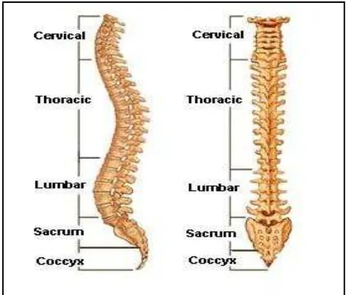
Figure 2.1 The lateral (side) and posterior (back) structure of spinal column. Adapted from www.spineuniverse.com.
3
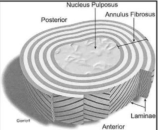
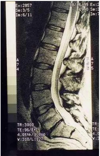
Figure 2.2 The intervertebral disc. Adapted from Devereaux, 2009. 4 Figure 2.3 Lumbar region of spine. Adapted from www.spineuniverse.com. 5 Figure 2.4 MRI of lumbar spine with degenerative disc disease (DDD) at
L5-S1. Adapted from www.spine-health.com.
6
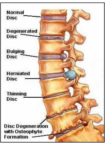
Figure 2.5 Example of degenerative disc disease. Adapted from www.spineuniverse.com.
7
Figure 2.6 A.The normal intervertebral disc B. Degenerate lumbar intervertebral disc. Adapted from Urban and Robert, 2003.
7
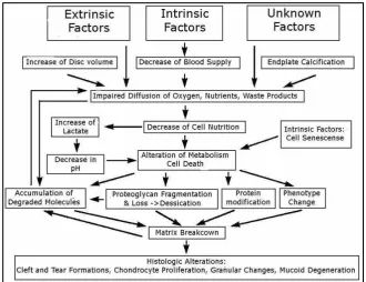
Figure 2.7 Schematic presentation of the possible pathomechanisms involved in the age-related changes. Adapted from Jongeneelen, 2006.
8
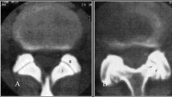
Figure 2.8 A. Normal facet B. Notice reduction of the joint space. Adapted from www.nsmec.com.
9
Figure 2.9 Lumbar fusion (arthrodesis). Adapted from www.spineuniverse.com.
10
Figure 2.10 Different lumbar artificial disc concepts. Adapted from Palepu, 2012.
12
Figure 2.11 Charite artificial disc. Adapted from www.depuyaccromed.com. 13 Figure 2.12 Prodisc-L artificial disc. Adapted from
www.synthes-stratec.com.
14
Figure 2.13 Maverick artificial disc. Adapted from www.back.com. 14 Figure 2.14 Flexicore artificial disc. Adapted from www.spinecore.com. 15 Figure 2.15 Removed polyethylene core L4-5 (left) and L5-S1 (right) after
6.5 years of insertion with a fracture of the metal wire and damage of disc prostheses. Adapted from Punt et al, 2007.
xi
Figure 2.16 Endplate fracture in patient. Adapted from Rosen et al, 2009. 16 Figure 2.17 Subsidence of disc prosthesis A. Lateral radiograph of the
lumbar spine in 1992, soon after disc replacement at L4–L5. B. Lateral radiograph of the lumbar spine 8 years postoperatively. Adapted from Van Ooij et al, 2003.
16
Figure 2.18 Overview of late complications after receiving disc prosthesis. Adapted from Punt et al, 2007.
17
Figure 2.19 The stress distribution on the original intervertebral disc and Charite artificial disc. Adapted from Muhammed Rafiq, 2010.
18
Figure 2.20 Total displacements of the original intervertebral disc, and Charite artificial disc under physiological loading. Adapted from Muhammed Rafiq, 2010.
18
Figure 2.21 Compressive stresses on the Charite (mobile-core) and Prodisc-L (fixed-core) core for central and anterior placement. Adapted from Missoum Moumene, 2007.
19
Figure 3.1 Step involved in constructing finite element of lumbar model 21 Figure 3.2 Prodisc-L artificial disc A. Superior endplates B. Polyethylene
inlays C. Inferior endplates.
22
Figure 3.3 The assembly of the implant. 22
Figure 3.4 The mesh of implant components. 23 Figure 3.5 The mesh of L4 and L5 vertebrae body. 24 Figure 3.6 Front and side view surgery of implant. 24 Figure 3.7 The finite element model subjected to a physiologic compressive
load of 400 N.
25
Figure 3.8 The maximum displacement is 1.801mm. 26 Figure 3.9 The value of compressive stress is 1.499 kPa. 26 Figure 3.10 The finite element model subjected to a physiologic compressive
load of 400 N.
27
xii
LIST OF TABLE
Table 2.1 Type of lumbar artificial disc 11
Table 3.1 Table of material properties. Adapted from Dietrich, 2005 25 Table 4.1 Comparison between compressive stress predicted on the
current model and literatures
xiii
LIST OF APPENDIX
Appendix 1 Technique Guide 40
Appendix 2 Gantt Chart for PSM I 41
xiv
NOMENCLATURE
E
Ν
–Elastic Modulus –Strain
–Stress
xv
ABBREVIATIONS
LBP DDD CAD 3D MRI TDR CT FE ROM
–Low back pain
–Degenerative disc disease –Computer-aided design –Three-dimensional
–Magnetic resonance imaging –Total disc replacement –Computed tomography –Finite element
CHAPTER 1
INTRODUCTION
1.1Overview
Low back pain (LBP) is a pain that occurs at lumbar region due to the flexibility and tends to received most stress compare to other region of spine. LBP is the leading cause of disability. A variety of pathologies can cause low back pain, one of which is degenerative disc disease (DDD). DDD can result in abnormal motion of the segment and biomechanical instability causing pain. Surgery is considered as other treatment options when conservative treatment fails (Van Den Eerenbeemt, 2010).
Fusion technique has been the traditional surgical treatment for low back pain but is often associated with unconvincing results, prolonged recovery time and future degeneration at adjacent level. The latest development in spine surgery has developed an alternative in the treatment of chronic low back pain from degenerative disc disease symptoms, the lumbar artificial disc replacement. But the disc is still under clinical trial, as the complication of the prosthesis still under studies. The possible short and long term unsatisfactory result from disc prostheses surgery is still ongoing by the researcher in term of longevity of the implant, the forces transmitted at the operated level and adjacent levels, and ultimately the clinical outcome for the patient.
2
1.2Problem Statement
There are several complications occurred on the lumbar artificial disc replacement, especially on the polyethylene core which be the main source of pain after the surgery. The purpose of this study is to investigate the effects of the compressive stress to artificial disc replacement prostheses using computational method by develop 3D model of current prostheses using Solid-works CAD software and simulation of finite element model.
1.3Objective
The objective of this study is to investigate the effect of the artificial disc replacement prostheses for degenerative disc disease patient.
1.4Scope
The scopes of study are:
i. To develop 3D model of current prostheses
ii. To assemble the prostheses model into human vertebral-segment model.
3
CHAPTER 2
LITERATURE REVIEW
2.1 Structural Anatomy of Human Spine
The human spine is a complex structure that provides both mobility and stability, and also protects the spinal cords. The vertebral column consist of seven cervical vertebrae (C1-C7), twelve thoracic vertebrae (T1-T12), five lumbar vertebrae (L1-L5), the sacrum which consist of five fused segments (S1-S5), and the coccyx as shown in Figure 2.1.
4
The different curvatures in each mature vertebral column help to form the posterior wall of the pelvis. The cervical spine from the first cervical through the second thoracic vertebra is convex forward, the thoracic curve from the second to the twelfth vertebra is convex backward, the lumbar curve from T12 to the lumbosacral junction is convex forward, and the sacrum and coccyx are concave forward (and convex backward).
Each region spine has its own function, the cervical spine support load from the weight of the head and allow for its rotation, and the thoracic region is only experience little movement. The lumbar region is the most flexible and tends to experience most motion compared to other region due to the pressure from the body weight.
2.2 Intervertebral Disc
The vertebra is connected by intervertebral disc between the vertebral bodies starting from the second cervical to the first sacral level. The intervertebral discs being thicker at levels where the vertebral bodies are taller as it is vary in thickness at different spinal level. The intervertebral disc is composed of a tough layer of ligament, the annulus fibrosis which does receive some blood supply from adjacent vessel, and the nucleus pulposus. The structure acts a shock absorber to cushion the vertebrae during movements of the spine, provides flexibility and helps to transmit vertical, horizontal and torsional forces, which support the vertebra and the entire weight of the upper body (Urban and Robert, 2003).
5
The intervertebral disc is responsible to withstand all the compressive loading subjected to vertebral body includes different types of load stresses, like dynamic loads, static loads, tensile stresses, torsional loads, shear stresses and combination of tensile, compressive and shear stresses (Jongeneelen, 2006). The water content of the disc decreased then causing spinal disc degeneration and increased lower back pain among older people (Keivan, 2010).
2.3 Spine-related disease and Low Back Pain
Spine-related disease, such as pain in the neck, mid back and low back is a most common problem in adult which lead to limitation of movement. There are many potential source of pain such as from the bone, joints, ligaments, muscles, nerves, and intervertebral disks. Also, due to posterior body condition and some other routine activity include certain occupations.
Figure 2.3 Lumbar region of spine. Adapted from www.spineuniverse.com.
6
physical activities usually experienced in work such as heavy lifting, bending and twisting, static work positions such as prolonged sitting or standing, exposure to whole body vibration, certain psychological and psychosocial work factors, depression, obesity, cigarette smoking, etc (Bartleson and Gordon Deen ,2009).
Variety of pathologies can cause LBP, one of which is degenerative disc disease (DDD) as shown in Figure 2.4. It has been hypothesised that through intervertebral disc dehydration, annular tears, and loss of disc height or collapse, DDD can result in abnormal motion of the segment and biomechanical instability causing pain (Van Deen Eerenbemt, 2010).
Figure 2.4 MRI of lumbar spine with degenerative disc disease (DDD) at L5-S1. Adapted from www.spine-health.com.
2.4 Degenerative Disc Disease
7
DDD can be both abnormal mechanical as abnormal chemical factors within the interveterbral disc which are reflected in the disc composition, structure and properties.
Figure 2.5 Example of degenerative disc disease. Adapted from www.spineuniverse.com.
Figure 2.6 A.The normal intervertebral disc B. Degenerate lumbar intervertebral disc. Adapted from Urban and Robert, 2003.
DDD occurs as a part of aging, also caused by environmental and genetic factors and ultimate mechanical factors. The most significant biochemical change to occur in disc degeneration is loss of proteogly as shown in Figure 2.7. The loss of proteogly is a major effect on the disc’s load
8
no longer behaves hydrostatically under load and inappropriate stress peaks may occur which can lead to cleft and tear formation (Jongeneelen, 2006).
Figure 2.7 Schematic presentation of the possible pathomechanisms involved in the age-related changes. Adapted from Jongeneelen, 2006.
2.5 Facet Joint Degeneration
Facet joint is a complicated biomechanical structure in the spine that provides a low-friction interface to facilitate motion during normal conditions in a healthy spine (Jaumard, 2011). They also play an important role in load transmission through the vertebrae, where the normal facets carry 3% to 25% of the load applied at the vertebra and potentially as high as 47% if the facet joint is arthritic. Because of their high level of mobility and the large forces influencing the facet joints, especially in the lumbar area, the joints can develop significant degenerative changes.
9
long-term fixation is desired to prevent migration or subsidence of the prostheses (Ooij, 2003).
Figure 2.8 A. Normal facet B. Notice reduction of the joint space. Adapted from www.nsmec.com.
2.6 Conventional Treatment of Low Back Pain
The best approach treatment for patient who has acute or chronic back pain includes of (Savigny, 2009);
i. Education; including advice from practitioners regarding exercise and cause of back pain, formal education session and written education material
ii. Exercise; including group and individual supervised exercise iii. Manual therapies; including manipulation, massage, mobilization
iv. Other non-pharmacological interventions; including interferential, laser, lumbar supports, transcutaneous electrical nerve simulation, traction, ultrasound
v. Invasive procedures; including acupuncture, electro-acupuncture, nerve blocks, neuroreflexotherapy, percutaneous electrical nerve stimulation (PENS), injection of therapeutic substance into the spine,
vi. Surgical referral and vii. Medications