Azma Putra*, Ahmad Yusuf Ismail and Md. Razali Ayob Faculty of Mechanical Engineering,
Universiti Teknikal Malaysia Melaka 76100, Hang Tuah Jaya
Melaka, Malaysia
*Corresponding email: [email protected]
Abstract
The micro-perforated panel (MPP) has been developed as a sound absorber which replaces the classical synthetic fibrous material. Known as the ‘hygenic’ acoustic material, its optical surface also makes it attractive enhancing the art of a room interior. This paper discusses the possibility to apply the MPP which substitutes the solid panel at the inner side on the double-leaf partition of vehicle structures to control sound absorption in the vehicle cabin. Having known as an important part of modern lightweight structures such as aircraft fuselages, train walls, car doors, windows and lightweight partition walls in buildings, the double-leaf partition has poor noise insulation at low frequencies due to the coupling between the partition masses and the air between them. The presence of the micro holes adds additional damping which breaches this coupling and increases the sound transmission loss. This can be controlled by tuning the properties of the MPP, i.e. the hole diameter, the perforation ratio and the cavity gap. The solid-MPP (SMPP) system therefore provides double functions simulatenously, i.e. as sound absorber and noise barrier. Derivation of the mathematical model for the transmission loss of the SMPP subjected to oblique and diffuse field incidence of acoustic loading is presented.
Keywords: Sound transmission loss, double-leaf, partition, micro-perforated panel, oblique incidence
1. INTRODUCTION
Sound quality in a room becomes the important factor for certain buildings. Theatre hall, music studio, lecture room and meeting room are some examples of rooms where the sound produced inside should be well controlled in order to provide the best quality of hearing. Over decades, this can be obtained by placing porous or abrasive absorber materials on the wall. Since the micro-perforated panel (MPP) is found to have a good performance as a sound absorber, this MPP is then widely developed and started to be employed instead of the conventional porous absorber. Besides the performance, this MPP also provides a ‘hygienic’, modifiable and attractive absorber material. 1.1. Micro-perforated panel (MPP)
Dah You Maa in 1975 first proposed a micro-perforated panel (MPP) as a sound absorber [1]. MPP is a panel containing micro-size holes on its surface. The hole diameter must be less than 1 mm and the perforation ratio should be in range between 0.5-1.5%.
The MPP has good sound absorption performance at a narrow low frequency corresponding to the Helmholtz resonator frequency.
Fig.1. The implementation of MPP as a sound absorber in front of the window at University Freiburg lecture hall [6]
Over the years, the researchers are focused on how to increase the frequency range of its absorption. Some
established works include coupling the MPP into a double-panel system [2], modifying the hole shape [3] and partitioning the back cavity [4]. Improvement on its mechanical strength has also been investigated [5].
Fig. 1 shows the implementation of MPP as a sound absorber in a lecture hall. The MPP is placed in front of the window in order to provide a good sound quality level inside the hall. The acrylic glass transparent material is used for the MPP to keep the aesthetic of the room.
1.2. Double-leaf partition
Since past decades, noise level in the vehicle interior has been subjected to customer satisfaction. A good quality vehicle should have low noise level in its cabin to provide a comfort room for passengers. Besides applying trim materials on the vehicle walls, a double-panel partition is also found to have a good performance as noise insulation. However, for noise source predominantly at low frequency, the so-called ‘mass-air-mass’ resonance phenomenon makes the performance of the double-panel becomes poorer than the single one [7].
Fig. 2 shows the comparison of an experimental result between a single and double-panel partition. It can be seen the ‘mass-air-mass’ resonance for the double-panel occurs at around 100 Hz and makes the TL performance drops significantly far below that of the single panel.
Fig. 2. Comparison of the transmission loss of a single and double-leaf partition [8]
Several works have been done to improve the performance at the mass-air-mass resonance. This includes placing a Hemholtz resonator inside the gap [8], embedding long T-shaped resonators [9], installing loudspeaker and actuator between the gap [10] and introducing absorber materials in the gap [11].
The existing research by the authors about the
implementation of MPP in a solid-micro-perforated panel (SMPP) system as noise barrier subjected to normal incidence of sound excitation shows that the improvement can be achieved around mass-air-mass resonance frequency, but reduces the TL performance at mid-high frequency [12]. This paper proposed a model for an oblique incidence of acoustic loading for the same SMPP system to simulate a more real application. The mathematical model for the TL is derived in the next section.
2. THEORY
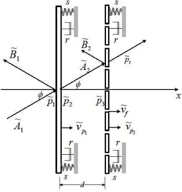
A mechanical system of a SMPP is shown in Fig. 3. It is a uniform, infinite and flexible panels having mass per unit area P supported by viscous damper r and elastic suspension s excited by an oblique incidence of acoustic loading with arbitrary angleI.
The component of the incident wave number vector which is directed parallel to the panel is kz ksinI. Since the panel is uniform and infinite, the bending wave induced in the panel must also have a wave number kz ksinI . The incidence and reflected pressures are given by
I I sin cos ~
~ Ae jkx jkz
i
p (1)
I I sin cos ~
~ jkx jkz
r Be
p (2)
where k Z/c is the acoustic wave number and c is the speed of sound. According to the analysis of a single-leaf transmission, the inertial components of wave impedance greatly exceeds the stiffness components at well below critical frequency, so that for the rest of discussion the inertial components will be neglected.
Fig. 3. Mathematical diagram of a SMPP under oblique incidence of acoustic loading
(2), the particle velocity at the first panel x 0 is given by
1 1 ~ ~ 1~ A B
c
v
U (3)
where U is the density of air. This particle velocity v~ at the first panel is same with panel velocity v~psince the panel is solid. Therefore, equation (3) becomes
1 1 ~ ~ ~ 1 B A v z p
f (4)
where zf Uc is the impedance of the air and 1 ~
p
v is the velocity of the first panel. At x 0 the acoustic pressure acting on the panel is
r
i p
p B A
p ~ ~ ~ ~
~
1 1
1 (5)
2 2 2
~ ~
~p A B (6)
while at x d
jkd jkd e B e A
p3 ~2 ~2
~ (7)
v z pt f
~ (8)
The presence of holes on the second panel makes the particle velocity no longer the same with the panel velocity. The mean particle velocity v as in (8) is obtained from Takahashi and Tanaka’s model [13]
f
p v
v
v ~21W W~ (9) where ~vp2 is the velocity of the second panel, v~f is the fluid velocity inside the holes and
W
is the perforation ratio.The hole impedance consist of real and imaginary part Zo Zo,RZo,I which according to Maa [6] is given by
»
»
¼
º
«
«
¬
ª
¸¸
¹
·
¨¨
©
§
¸¸
¹
·
¨¨
©
§
t d X X d t vZ o o o
o a R o 9 32 1
32 2 1/2
2
2 , (10)
»
»
¼
º
«
«
¬
ª
¸
¹
·
¨
©
§
¸
¸
¹
·
¨
¨
©
§
t o d o X t j ZoIS UZ 3 8 2 / 1 32 2 9 1 , (11)
where Xo
do/2ZU/va and the air viscosity va. The real part or the resistive part of the impedance represents the viscous effect of air interaction with the wall surface of the holes. While the imaginary part or inertial part represents the inertia of the air mass inside the holes. The net force acting on the panel is therefore Zo,Rv~fv~p2Zo,I~vf 'p (12)Equation (12) is then substituted into (9) to give the mean particle velocity
Z p v
v J~p2' (13) where J 1
>
Zo,I/Z@
and Z Zo/W.The equation of motion for the second panel is given by
v v IJZ
IJ
p v
zp p oR f p
2 2 2 ~ ~ 1 ~ ,
' (14)
where 2
p
z is the mechanical impedances of the second panel, which is now due to bending is given by [1]
IZ K PZ I
Z 4sin4 4 4sin4
2 k D Dk j z
p (15)
where Kis the damping loss factor of the panel and )
1 ( 12
/ 2
3 Q Et
D is the bending stiffness, with E the Young’s modulus and Q the Poisson’s Ratio and the second term on the right hand side of (14) is the viscous force inside the hole. Substitute (12) to (14) yields
2 ~
p
v
p :
' (16)
where : is the modified panel impedance due to the perforations given by
¸¸
¹
·
¨¨
©
§
) : Z Z ZZp o,R o,I 2
1
(17)
and
Z Zo,R
1
) W .
The expansion of (7) yields
~ ~ cos( cos ) ~ ~ sin( cos ) ~2 2 2
2
3 A B kd I j A B kd I
p
sin( cos )
~ ) cos cos( ~ 1
2 kd I jz v kd I
p f p (18)
The equation of motion of the first panel is
2 1 ~
~ ~
1
1v p p
zp p (19)
where 1 ~
p
z is the mechanical impedance as in (15). Using Euler equation for (7) and substitute to (6) yields the pressure at x = 0+(right side surface of the solid panel)
) cos sin( ) cos cos( ~ ~ 1 2 I I kd j v kd v zp f p
(20) Note that ~
~2 ~21 A B
v
zf p has been used in (20),
equivalent to (3). Substituting (20) to (18) gives
) cos sin( ) cos cos( ~ ~ 1 3 I I kd j kd v v zp f p (21)
t
p p p ~3~
' (22)
By substituting (21) and (8) into (22) gives
Substituting (13) into (22) and then to (16) gives the ratio of the panel velocity
» » ¼ º « « ¬ ª : Z e z kd j e v v jkd f jkd p
p J cosI sin( cosI) cosI
~ ~
2 1
(24)
Using (4) and note that A~1 p~i and B~1 p~r gives
1 ~ ~ ~ p f i
r p z v
p (25)
Substituting (5), (20) and (25) into (18) yields the incident pressure
¿
¾
½
¯
®
) cos sin( ) cos cos( ~ ~ ~ 2 1 ~ 1 1 1 1 I I kd j v kd v z v z v zpi p p f p f p (26)
This pressure is then divided by p~t Ucv to obtain the ratio of the incident pressure and the transmitted pressure ° ° ¿ ° ° ¾ ½ ° ° ¯ ° ° ® ¸ ¹ · ¨ © § ¸ ¹ · ¨ © § ¸ ¸ ¹ · ¨ ¨ © § : : ) cos sin( cos ) cos sin( ~ ~ 2 1 ~ ~ 1 2 1 I J J I I kd j Z Z jkd e z kd jz v v p p f p p p t i (27) Substitute (24) into (27) finally gives
kd j Z Z kd Z kd j jkd f p jkd f jkd t i e z jz e z e p p sin 2 ) cos sin( ) cos sin( 1 cos ~ ~ ¸ ¹ · ¨ © § ¸ ¹ · ¨ © § ¸ ¸ ¹ · ¨ ¨ © § u ¸ ¸ ¹ · ¨ ¨ © § ) : : : J J I I I
J
(28)The transmission coefficient V is therefore 2 ~ ~ i t p p
V (29)
and the transmission loss is expressed as
V
log
10
u
TL
(30)3. RESULTS AND DISCUSSION
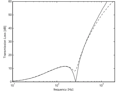
The theoretical results of sound transmission loss of conventional solid double-panel (SDP) and SMPP under a 300 oblique incidence of acoustic loading is shown in Fig.4. The calculation is performed for a plate with 1 mm thick, 2700 kg/m3 density. The hole diameter of the MPP is 0.1 mm and has 0.5%
perforation ratio. It can be seen the common mass-air-mass resonance occurs on the SDP at around 280 Hz where the TL performance is dropped to almost zero dB. Meanwhile the SMPP can be seen to overcome the problem by around 6 dB of improvement. The mass-air-mass resonance frequency happens when both panels as well as the air inside the gap are moving in phase, so that the transmission of sound is multiplied. Since the second panel is constructed with micro-holes, additional damping is added from the existing viscous force inside the holes between the air and the inner wall surface which in turn breaches the mass-air-mass coupling.
101 102 103 0 10 20 30 40 50 60 frequency [Hz] T ra n sm issi o n L o ss [ d B ]
Fig. 4. Sound transmission loss of a solid double-panel (SDP) and SMPP under 30o incidence of acoustic loading
(—SDP, ---SMPP)
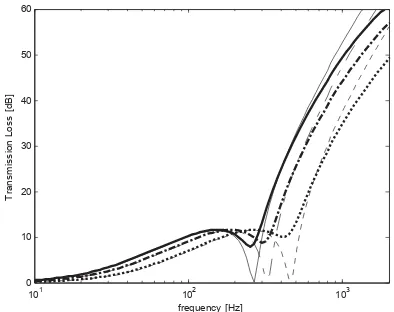
Fig. 5 shows the increment of incidence angles to the TL performance. The MPP parameter is kept constant which are do = 0.1 mm and 0.5% perforation
ratio. It is shown that the increment of incidence angle increases the resonance frequency which in consequence, also shifts the TL performance above the resonance to higher frequency.
101 102 103 0
10 20 30 40 50 60
frequency [Hz]
T
rans
m
is
s
ion Los
s
[
dB
]
Fig. 5. Sound transmission loss of SDP (thin line) and SMPP (thick line) under different angle of incidence I,
(—I=30o, – - –I=45o, ----I=60o )
101 102 103
0 10 20 30 40 50 60
frequency [Hz]
T
rans
m
is
s
ion Los
s
[
dB
]
Fig. 6 Sound transmission loss of SDP (thin line) and SMPP (thick line) under 30o oblique incidence of acoustic
loading with different gap distance d. (—d = 5 cm, – - –d = 3 cm, ----d = 1 cm )
Fig. 7 and 8 shows the effect of the hole diameter and perforation ratio to the TL performance. Fig. 7 shows that increasing the hole diameter improves the TL at the mass-air-mass resonance. It can also be seen that doubling the diameter from 0.2 mm to 0.4 mm shows less effect at the resonance compared with 0.1 mm to 0.2 mm. This is because as the hole becomes larger, the resistive component which responsible for the friction (viscous) force becomes less dominant compared with the inertial component [14]. As in previous results, above the resonance the TL is lower than that of the SDP.
Fig. 8 shows that the TL at the resonance increases as the number of holes are increased as this provides more viscous force hence creating more damping. Again, above the resonance, the TL reduces as the perforation ratio increases.
101 102 103
0 10 20 30 40 50 60
frequency [Hz]
T
ran
s
m
is
s
ion Los
s
[
d
B
]
Fig. 7. Sound transmission loss of SMPP under 30o oblique incidence of acoustic loading with different
hole diameter do , constant gap distance d = 5 cm and
constant perforation ratio IJ = 0.5% (—SDP, – – do = 0.1 mm, – - – do = 0.2 mm,
---- do = 0.4 mm )
101 102 103 0
10 20 30 40 50 60
frequency [Hz]
T
ra
n
sm
issi
o
n
L
o
ss
[d
B
]
Fig. 8. Sound transmission loss of SMPP under 30o oblique incidence of acoustic loading with different
perforation ratio IJ and constant hole diameter 0.1 mm. (– –IJ = 0.5%, – - –IJ = 1%, ----IJ = 1.5% )
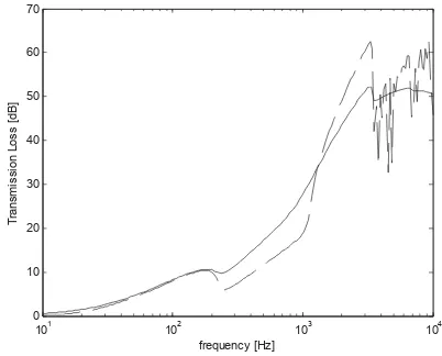
In order to obtain the transmission loss for diffuse field, the TL is the summation from all angle of incidence has been proposed by Fahy [1]
³ ³
³ /2
0 2
/
0 2 /
2 sin ) ( cos
sin cos sin ) (
0 S
S S
I I I W I
I I
I I I I W
W d
d d
d
(31)
101 102 103 104 0
10 20 30 40 50 60 70
frequency [Hz]
T
ra
n
sm
is
si
o
n
L
o
s
s
[d
B
]
Fig. 9. Comparison between sound transmission loss of SDP and SMPP with do = 0.1 mm, IJ = 0.5%,
air gap distance d = 5 cm under diffuse field incidence (----SDP, —SMPP).
4. CONCLUSION
Under oblique incidence of acoustic loading, the SMPP system is found to be effective to overcome the mass-air-mass resonance problem of the double-leaf. The improvement can be optimized by tuning the parameter of the MPP i.e the gap distance, hole diameter and perforation ratio. The improvement at mass-air-mass resonance for the diffuse field incidence has wider band of frequency range compare to that for the single angle incidence. It is therefore feasible to apply this system for the vehicle interior to act as the noise barrier, although the sound insulation performance decreases at high frequency above the resonance. Improvement for this problem will be investigated in the future work.
5. AKNOWLEDGEMENT
This research is funded by The Fundamental Research Grant Scheme (FRGS) of the Ministry of Higher Education (MOHE) Malaysia in Universiti Teknikal Malaysia Melaka.
6. REFERENCES
[1] Maa, D., “Theory and design of microperforated panel sound absorbing construction (in chinese).” Scientica Sinica, vol:18, 1975, pp.55-71.
[2] Sakagami, K., Morimoto, M., and Koike, W., ”A numerical study of double leaf microperforated panel absorber.” Applied Acoustics, vol:67, 2006, pp.609-619.
[3] Pfretzschner, J. and Cobo, P., “Microperfoated insertion units : An alternative strategy to design microperforated panels.” Applied Acoustics, vol:67, 2006, pp.62-73.
[4] Sakagami, K., Morimoto, M., Yairi, M., and Minemure, A., “A pilot study on improving the absorptivity of a thick micoperforated panel absorber,” Applied Acoustics, vol:60, 2008, pp.179-182.
[5] Liu and Herrin, “Enhancing microperforated panel attenuation by partitioning the adjoining cavity,” Applied Acoustics, vol:71, 2010, pp.120-127. [6] Fuchs, H.V., Zha, X. “Micro-perfprated structures
as sound absorbers : A review and outlook” Acta Acustica United with Acustica, vol:92, 2006, pp.139-146.
[7] Fahy, F., “Sound and Structural Vibration : Radiation, Transmission and response.” Academic Press, 2007.
[8] Mao, Q., Pietrzko, S., “Control of sound transmission through double wall partition using optimally tuned Hemholtz resonators.” Applied Acoustics, vol:91, 2005, pp.723-731.
[9] Li, D., Zhang, X., Cheng, L., nad Yu, G., “Effectiveness of T-shaped acoustic resonators in low frequency sound transmission control of a finite double-panel partition.” Journal of Sound and Vibration, vol:329, 2010, pp. 4740-4755. [10]Li and Cheng, “Mechanism of active control of
sound transmission through a linked double wall system into an acoustic cavity,” Applied Acoustics, vol : 69, 2008, pp. 614-623.
[11]Alba, J., Ramez, J., and Snachez, V., “Improvement of the prediction of transmission loss of double panel with cavity absorption by minimization techniques” Journal of Sound and Vibration, vol:273, 2004, pp.793-804.
[12]Ismail, A.Y., Putra, A., Ayob, Md. R., “Sound transmission loss of a double-leaf solid-microperforated partition under normal inccidence of acoustic loading.” Proceeding of the International Conference of Mechanical, Automotive and Aerospace Engineering (ICMAAE), Malaysia, 2011
[13]Takahashi, D., and Tanaka, M., “Flexural vibration of perforated plates and porous elastic materials under acoustic loading,” Acoustical Society of America, vol:112, 2002, pp.1456-1464.
![Fig.1. The implementation of MPP as a sound absorber in front of the window at University Freiburg lecture hall [6]](https://thumb-ap.123doks.com/thumbv2/123dok/592033.70687/1.595.296.524.546.698/fig-implementation-sound-absorber-window-university-freiburg-lecture.webp)