INSERTION OF A MICRO-PERFORATED PANEL TO IMPROVE
SOUND TRANSMISSION LOSS OF A DOUBLE-LEAF PARTITION
A.Y. Ismail
*, A. Putra, Md. R. Ayob
Faculty of Mechanical Engineering, Universiti Teknikal Malaysia Melaka
Hang Tuah Jaya 76100, Malaysia
*Email: [email protected]
Abstract—Over decades a double-leaf partition in engineering structures has been widely applied for its advantages i.e. in terms of the mechanical strength and toughness as well as its lightweight property. For noise control application, the double-leaf has also been known to be an effective noise barrier. Unfortunately at resonance frequency, the sound transmission loss (TL) reduces significantly due to the coupling between the panels and the air between them. This paper investigates the effect of a micro-perforated panel (MPP) inserted inside a double-leaf partition to improve the TL performance at the troublesome resonance frequency of a conventional double-leaf structure. It is found that the TL improves at the resonance if the MPP is located closer to the solid panel. The mathematical model is derived for normal incidence of acoustic loading.
Keywords—Double-leaf, partition, micro-perforated panel, transmission loss.
I. INTRODUCTION
A double-leaf structure is a common structural design for many engineering applications. The vehicle body such as in cars, trains and airplanes, as well as the walls of a building are some examples of double-leaf partition in practice. From the acoustical engineering point of view, the double-leaf is proposed to be a better noise barrier compared to the single-leaf. However, there remains a problem on the double-panel which is the weak sound transmission loss (TL) performance at low frequency due to the ‘mass-air-mass’ resonance. This causes the double-leaf loses its superiority over the single-double-leaf [1]. Several works have been done to improve this problem. This includes installing the Hemholtz resonators at the air gap between the panels [2] and using active control system to control the acoustic modes in the gap [3]. The feasibility of installing a micro-perforated panel (MPP) into double-leaf structure is then possible since it has a good performance of sound absorption. It has been found from author’s previous work that substituting the solid back panel into MPP is also effective to overcome the resonance problem [4]. This paper proposes MPP insertion inside the air gap of the double-leaf as an alternative way to improve the transmission loss. The effect of the MPP distance in the gap with respect to the solid panels and the holes properties are also investigated.
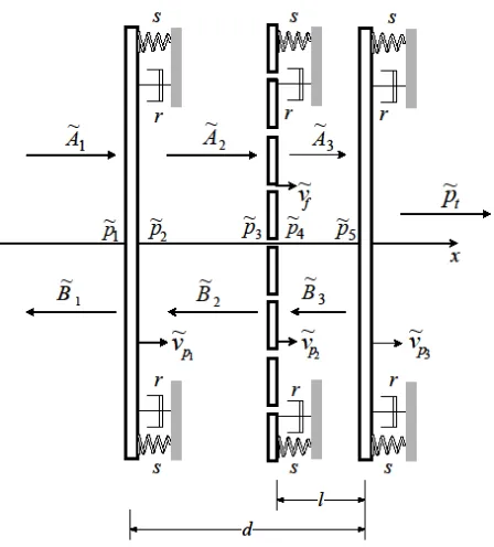
Figure. 1. Mechanical system of DL-MPP under normal incidence of
acoustic loading
II. GOVERNING EQUATION
A. Acoustic pressure
A mechanical system of a double-leaf with MPP insertion (DL-MPP) under normal incidence of acoustic loading can be seen in Fig. 1. Each panel has mass per unit area
µ
and is assumed supported on spring with stiffness per unit area s and on a damper with damping per unit area r. It is assumed that the distance between the solid panel d is much smaller compared to the acoustic wavelength (kd <<1). The incident and reflected pressure are expressed asjkx i Ae p = ~1 −
~
(1)
jkx r Be p ~1
~ =
(2)
4 – 6 April 2012
on the panel can be written as
r
i p
p B A
p ~ ~ ~ ~
~
1 1
1= + = +
(3)
1 1 1
~
~
~
A
B
v
z
f p=
−
(4)
2 2
2
~
~
~
p
=
A
+
B
(5)
2 2
1
~
~
~
A
B
v
z
f p=
−
(6)
while at x = d-l ) ( 2 ) ( 2 ~ ~ jkd l jkd l
fv Ae B e
z = − − − −
(7)
) ( 3 ) ( 3 ~ ~ jk d l jk d l
fv Ae Be
z = − − − −
(8)
and at x = d,
jkd jkd
p
f
v
A
e
B
e
z
3 3 3~
~
~
−
=
−(9)
3
~ ~
p f t z v
p =
(10)
where zf =
ρ
c is the acoustic impedance of the air withρis the density of the air, l is the distance between the MPP and the solid back panel, v~p is the velocity of the solid panel and v is the mean particle velocity over the MPP surface
Since the distance between the panel is small compared to the acoustic wavelength, the cavity pressures are assumed to be uniform. Therefore,
c p B A p
p ~ ~ ~ ~
~
2 2 3
2≈ = + = (11)
d
p B A p
p ~ ~ ~ ~
~
3 3 5
4 ≈ = + = (12)
At x = d-l, Eqs.(7) and (8) can be expanded into
(
)
(
cos ( ) sin ( ))
~ ) ( sin ) ( cos ~ 2 2 l d k j l d k B l d k j l d k A v zf − + − − − − − = (13)(
)
(
cos ( ) sin ( ))
~ ) ( sin ) ( cos ~ 3 3 l d k j l d k B l d k j l d k A v zf − + − − − − − =(14)
By using Eqs.(11) and (12), and note that kd <<1, Eqs. (13) and (14) can be re-written as
c
fv A B jk d l p
z = ~2−~2− ( − )~ (15)
d fv A B jk d l p
z = ~3−~3− ( − )~ (16)
using the same way to the pressures at x = d gives
) ( 3 3 3 ~ ~ ~ ~ d p
fv A B jkd p
z = − − (17)
As the cavity pressure is uniform, Eqs. (6) and (15) can be combined obtaining
) ( ~ ~ 1 l d jk v v z pc f p
− − = (18)
while from Eqs. (16) and (17) gives
jkl v v z
pd f p
= − 3 ~ ~ (19)
B. Mean particle velocity
As the acoustic pressure excites the MPP, the air particles penetrate the holes and excite the remaining solid surface. The combination between panel velocity and particle velocity inside the holes creates the mean particle velocity given by [5]
(
)
fp
v
v
v
=
~
21
−
τ
+
τ
~
(20)where
τ
is the perforation ratio andv
~
f is the particlevelocity inside the holes. The impedance of the holes
I o R o
o
Z
Z
Z
=
,+
, is given by Maa [6] where
+
+
=
t
d
X
X
d
t
v
Z
o o oo a R o
9
2
32
1
32
2 1/2 2 , (21) + − + + = t o d o X t j I o Zπ
ρω
3 8 2 / 1 32 2 9 1 , (22)where Xo
=
(
do/2)(
ωρ
/
va)
and va is the air viscosity.The resistive or real part of the impedance
Z
oR,
represents the viscous effect of air interaction with the panel surface and imaginary part
Z
oI, represents the
acoustic reactance from the inertia of the air inside the holes. The net force acting on the plate can be expressed as
(
v
v
)
Z
v
p
Z
o,R~
f−
~
p2+
o,I~
f=
Δ
(23)Re-arrange Eq. (23) and substitute to Eq. (20) gives the mean particle velocity as a function of the pressure difference Δp i.e.
Z p v
v= p +Δ
2
~
γ (24)
where
− = Z ZoI
,
1
γ
andZ
=
Z
o/
τ
.C. Sound transmission loss
t d p
p v p p
z 3~ 3 =~ −~ (25)
where
z
p=
j
ω
µ
+
r
+
s
/
j
ω
is the mechanicalimpedance of the panel. Substituting Eq. (19), Eq. (10) into Eq. (25) and using mean particle velocity in Eq. (24) then dividing both side with 3
~
pv
gives the panel velocity ratio
+
+
+
=
Zjkl
z
z
jkl
z
z
jkl
z
z
v
v
f p f f f p p p 2 3 3 2~
~
(26)The equation of motion for the MPP (usually small perforation) is expressed as
p v
zp2~p2=Δ (27)
Substituting the cavity pressures in Eq. (18) and Eq. (19) to Eq. (27) and again using mean particle velocity in Eq. (24) then dividing both side with 3
~
pv
yields
l
l
d
Zl
l
d
z
l
l
d
v
v
Z
z
z
l
d
jk
z
v
v
v
v
p p p p f p p p p p)
(
)
(
)
(
~
~
)
(
~
~
~
~
2 3 2 2 2 3 2 3 1−
−
−
+
−
+
+
+
−
=
γ
γ
(32) (28)Finally, the equation of motion of the first panel is expressed as
c p
pv p p
z 1~1=~1−~ (29)
By using relation between incident and reflected pressure in Eqs. (3) and (4) this is changed to be
) ( ~ ~ ~ 2 ~ 1 1 1 1 l d jk v v z v z p v
zp p i f p f p
− − − − = (30)
Again, dividing both side with
~
v
p3 and rearranginggives
−
+
−
−
−
+
+
=
)
(
)
(
~
~
)
(
1
1
~
~
~
~
2 3 2 1 3 1l
d
Zjk
z
l
d
jk
v
v
l
d
jk
z
z
v
v
p
p
p p p f p p p t iγ
(31)The transmission coefficient
σ
and the TL are therefore given by2 ~ ~ i t p p =
σ
(32)
=
σ
1
log
10
10 TL (33)III. RESULTS AND DISCUSSION
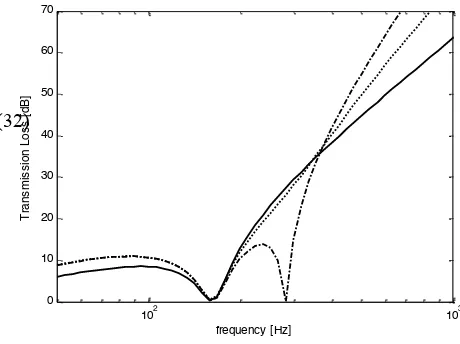
Figure 2 shows the transmission loss under normal incidence of acoustic loading for double-leaf (DL), triple solid panel (TSL) and DL-MPP for MPP located exactly at the middle of the two solid panels (l = 0.5d). It can be seen that the ‘mass-air-mass’ resonance of the DL occurs around 170 Hz shown by the ‘drop’ value of TL to 0 dB. It can also be seen that placing another solid panel between the DL (TSL) yields the second resonance at 280 Hz. This can be considered to worsen the problem although the TL at mid-high frequency significantly increases. The insertion of MPP between the DL (in the middle) overcomes the second resonance. However, the first resonance remain occurs due to the solid plates.
102 103
0 10 20 30 40 50 60 70 frequency [Hz] T ra n s m is s io n L o s s [ d B ]
Figure. 2. Sound transmission loss of a DL, TSL and DL-MPP,
do = 0.1 mm τ = 1.5%, and d = 100 mm under normal incidence of
acoustic loading
(— DL, – • – TSL, •••• DL-MPP with l = 0.5d )
4 – 6 April 2012
102 103
0 10 20 30 40 50 60 70
frequency [Hz]
T
ra
n
s
m
is
s
io
n
L
o
s
s
[
d
B
]
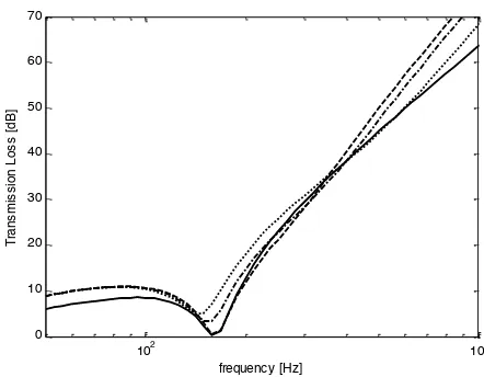
Figure. 3. Sound transmission loss of a DL and DL-MPP, do = 0.1 mm
τ = 1.5%, and d = 100 mm under normal incidence of acoustic loading (— DL, ••••l = 0.1d , – • – l = 0.25d ,– –l = 0.5d)
Figure 4 shows the effect of hole diameter of MPP to the TL. Around the resonance region up to 400 Hz, decreasing the hole diameter increasing the TL.
In Fig. 5, the effect of the perforation ratio is investigated. It can be seen that increasing the perforation ratio does not give significant differences to the TL of DL-MPP around the resonances. The effect of perforation ratio can be seen at high frequency.
102 103
0 10 20 30 40 50 60 70
frequency [Hz]
T
ra
n
s
m
is
s
io
n
L
o
s
s
[
d
B
]
Figure. 4. Sound transmission loss of a DL and DL-MPP, l = 0.1d,
τ = 0.5%, and d = 100 mm under normal incidence of acoustic loading (— DL, •••• do = 0.1 mm, – • – do = 0.2 mm, – – do = 0.4 mm)
102 103
0 10 20 30 40 50 60 70
frequency [Hz]
T
ra
n
s
m
is
s
io
n
L
o
s
s
[
d
B
]
Figure. 5. Sound transmission loss of a DL and DL-MPP, do = 0.1 mm,
l = 0.1d, and d = 100 mm under normal incidence of acoustic loading (— DL, •••• τ = 1.5%, – • – τ = 1%, – – τ = 0.5%,) For clarity of the analysis, the level of improvement or decrement of the TL can be represented by the insertion gain (IG), i.e. the ratio of the transmitted sound power after to before the MPP insertion which is given by
d
s
TL
TL
log
10
IG
=
−
=
d s
σ
σ
(34)
where TLs is the transmission loss of the DL-MPP and TLd is for the DL.
102 103
-5 0 5 10 15
frequency [Hz]
In
s
e
rt
io
n
G
a
in
[
d
B
]
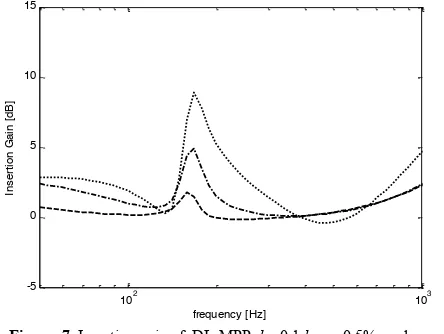
Figure. 6. Insertion Gain of DL-MPP, do = 0.1 mm τ = 1.5%, and
d = 100 mm under normal incidence of acoustic loading (— DL, ••••l = 0.1d , – • – l = 0.25d ,– –l = 0.5d)
102 103 -5
0 5 10 15
frequency [Hz]
In
s
e
rt
io
n
G
a
in
[
d
B
]
Figure. 7. Insertion gain of DL-MPP, l = 0.1d, τ = 0.5%, and
d = 100 mm under normal incidence of acoustic loading (— DL, •••• do = 0.1 mm, – • – do = 0.2 mm, – – do = 0.4 mm)
The improvement of DL-MPP transmission loss with different hole diameter is presented in Fig. 7. It can be seen that smaller hole is preferred for good TL performance.
102 103
-5 0 5 10 15
frequency [Hz]
In
s
e
rt
io
n
G
a
in
[
d
B
]
Figure. 8. Insertion gain of DL-MPP, do = 0.1 mm, l = 0.1d, and
d = 100 mm under normal incidence of acoustic loading (— DL, •••• τ = 1.5%, – • – τ = 1%, – – τ = 0.5%)
Figure 8 shows that varying the perforation ratio (with fixed hole diameter) gives almost no effect on the IG. Therefore, in order not to sacrifice the TL at high frequency, small perforation ratio is preferred.
IV. CONCLUSION
The mathematical model of transmission loss of DL-MPP system under normal field of acoustic loading has been derived. It is found that the MPP insertion reduces the effect of resonance found in the conventional double-leaf partition. However, this is only effective when the MPP distance is less than half of the air gap to the panel. Compromised situation has to be taken noted as bringing the MPP closer to the solid panel reduces the TL above the resonance frequency. Reducing the hole diameter of the MPP can also improves the TL at resonance while changing the perforation ratio gives no effect on the TL performance. The future works will include experimental work inside an impedance tube to validate this model.
ACKNOWLEDGMENT
The authors would like to acknowledge the Ministry of Higher Education (MoHE) Malaysia for supporting this work under Fundamental Research Grant Scheme; FRGS/2010/FKM/TK02/3-F0078.
REFERENCES
[1] Fahy, F., “Sound and Structural Vibration : Radiation, Transmission and response.” Academic Press, 2007.
[2] Mao, Q., Pietrzko, S., “Control of sound transmission through double wall partition using optimally tuned Hemholtz resonators.” Applied Acoustics, vol : 91, 2005, pp.723-731 [3] Li and Cheng, “Mechanism of active control of sound
transmission through a linked double wall system into an acoustic cavity,” Applied Acoustics, vol : 69, 2008, pp. 614-623.
[4] Ismail, A.Y., Putra, A. Ayob, Md. R. “Sound transmission loss of a double-leaf solid-microperforated partition under normal incidence of acoustic loading.” IIUM Engineering Journal, vol:12 (3), 2011, pp. 165-177
[5] Takahashi, D., and Tanaka, M., “Flexural vibration of perforated plates and porous elastic materials under acoustic loading,” Acoustical Society of America, vol : 112, , 2002, pp.1456-1464.