‘I/We’ declare that I have been done reading this report
And in my opinion, this report fulfill the condition in all
Aspect that must be in poject writing as need in partial fulfillment
For Bachelor Mechanical Engineering (Thermal-Fluids)
Signature
: ...
Supervisor Name I
: Mr. SUHAIMI BIN MISHA
DEVELOPMENT OF A MINI TURBINE TO GENERATE
ELECTRICITY
MOHD FAHMI BIN ABD. MAJID
This report had been done
In partial fulfillment
For Bachelor Mechanical Engineering (Thermal-Fluids)
Faculty of Mechanical Engineering
Universiti Teknikal Malaysia Melaka
ii
“I declare that this report had been done originally from me except some of them where I have been explain each one of them with its sources”
Signature : ...
Name : MOHD FAHMI BIN ABD MAJID
iii
Especially to my beloved parents, My respectfully lecturers,
Also my faithfully friends,
iv
ACKNOWLEDGEMENT
First of all, I would like to express my gratitude to the almighty Allah for his blessing in making me able to finish the PSM project. the idea, concept and everything which I got in this project making cannot be done without his blessing.
Secondly, millions of thanks to my supervisor, Mr. Suhaimi bin Misha, the head of the department Thermal-Fluids of Mechanical engineering for supervise me in this project making from the start until the end. Thank you for the time spend,
knowledge given, idea shared and for the support given.
Thirdly, I would like to thank to all who were responsible in this project making either involved directly or indirectly. Without all the helps received, I have learned so much.
v
ABSTRACT
This report majorly concerned about the development of mini turbine to generate electricity for home application. The idea is to use waste energy from the incoming water pipeline to rotate the turbine in order to generate electricity. This research and development had been made in order to define additional clean energy sources in decreasing the primary electrical sources which is majorly using a fossil fuel as sources of energy. The carbon dioxide produce from the combustion process had lead to greenhouse effect which is increasing the global temperature. The concept design of the system had been illustrated but there will be design considerations since the idea was based on theoretical and there might be changes in the experiment. The literature review section provides important knowledge of the topic study. It includes the turbine, electricity demand, past invention and the theoretical analysis. The methodology section stated the sequence of the project making from the proposal to the expected process. It make the project making process become smoothly and will increase the possibility of success. The experimental result section provides the related data regarding to the experiment includes data, procedure and the process of manufacturing. The analysis and
discussion section provides the detailed explanation and discussion related to the data and the subject study. Finally the discussion and recommendation section provides
vi
ABSTRAK
Laporan ini berkaitan dengan pembikinan turbin mini untuk menghasilkan elektrik untuk kegunaan rumah. Idea yang digunakan adalah untuk mengaplikasikan tenaga terbuang daripada paip air masuk untuk menggerakkan turbin bagi menghasilkan elektrik. Kajian dan penghasilan projek ini adalah bertujuan untuk mencari alternatif tenaga tambahan bagi mengurangkan penggunaan sumber elektrik utama yamg mana kebanyakannya bergantung kepada minyak mentah sebagai sumber kuasa utama. Karbon dioksida yang dihasilkan dalam proses pembakaran membawa kepada kesan rumah hijau dan akan meninggikan suhu global. Konsep
vii
CHAPTER I INTRODUCTION 1
1.1 Introduction 1
1.2 Objectives 4
1.3 Scope 4
1.4 Problem Statement 5
1.5 Methodology 6
CHAPTER II LITERATURE REVIEW 8
2.1 Introduction to Water Turbine 8
2.1.1 History of Water Turbine 8
2.1.2 Water Turbine and Its Application 11
viii
2.2 Electricity Demand 26
2.2.1 World Electricity Demand 26
2.2.2 Renewable Energy Sources 29
2.2.2.1 Hydro Electricity 29
2.3 Past Invention 31
2.3.1 Mini Hydro Turbine 31
2.4 System Design 33
CHAPTER III METHODOLOGY 35
3.1 Introduction 35
3.2 Flow Chart of the Methodology 36
3.3 Explanation of Methodology 38
3.3.1 Identifying Objectives, Scope and Problem 38 Statement
3.3.2 Literature Review 38
3.3.3 Collecting Information Regarding the
Project 38
3.3.4 Design the Concept of the System 39 3.3.5 Select Material and Component 39
3.3.6 Start Building the System 41
3.3.4.1 Designed Consideration 41
3.3.5 Run Experiment 42
3.3.6 Problem Analysis 42
3.3.7 Suggestion for Improvement 42
CHAPTER IV EXPERIMENTAL RESULT 43
4.1 Introduction 43
ix
CHAPTER V ANALYSIS AND DISCUSSION 52
5.1 Capability of Turbine to Produce Electricity Over 53 time
5.2 The Capability of Electricity Generated to be used 56 for Appropriate Application
5.3 The Electricity Estimated Can be Saved for a 58 Single Unit House
5.4 The Electricity Estimated Can be Saved from the 61 Global Consumption
CHAPTER VI CONCLUSION AND RECOMMENDATION 63
Conclusion 63
Recommendation 64
REFERENCES 66
BIBLIOGRAPHY 67
x
LIST OF FIGURES
NO. TITLE PAGE
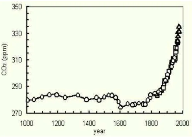
1.1 CO2 Production for last 1000 years 2
(Source: http://planetforlife.com/gwarm/glob1000.html)
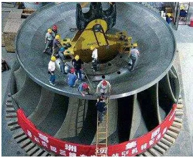
1.2 Hydro Turbines of three Gorges Dams in Construction 3 (Source: http://www.trelleborg.com/)
2.1 Ancient Illustrated Water Wheels 9
(Source: http://www.top-alternative-energy-sources.com/water- wheel-history.html)
2.2 Modern Water Turbine Design 10
(Source: http://www1.eere.energy.gov/windandhydro/hydro _rd.html)
2.3 Types of Water Turbine 11
2.4 Section View of Pelton Turbine 13
(Source: http://www.dermediamatiker.ch)
2.5 Pelton Turbine Runner 14
(Source: http://www.geppert.at/)
2.6 Working Principle of Pelton Turbine 15
(Source: http://electricalandelectronics.org/2008/09/24/constit uents-of-hydro-electric-plant/)
2.7 Cut-Section of Francis Turbine 16
(Scope: http://www.tfd.chalmers.se/~hani/phdproject/proright.html)
2.8 Runner of a Francis Turbine 17
(Source: http://www.topomatika.hr/Applications/Images/Big /turbine_09-b.jpg)
2.9 Working Principle of Francis Turbine 18
xi
2.1 Cut-Section of Kaplan Turbine 19
(Source: http://www.tfd.chalmers.se/~hani/phdproject/kaplanfoto.gif)
2.11 Propeller of a Kaplan Turbine 20
2.12 Kaplan Turbine Working Operation 21
(Source: http://re.emsd.gov.hk/english/other/hydroelectric/images /image008.gif)
2.13 Application Range of Hydraulic Turbine 22
(Scope: Fundamental of Turbomachinery)
2.14 Efficiency versus Specific Speed of hydro turbines 23 (Sources: Fundamental of Turbomachinery)
2.15 Relationship between specific diameter and specific 24 speed of hydraulic turbines
(Source: Fundamental of Turbomachinery)
2.16 World Electricity consumption 26
(Source: http://www.indexmundi.com/world/electricity_consu mption.html)
2.17 Energy Sources 27
(Source: http://en.wikipedia.org/wiki/File:2004_Worldwide_Energy_ Sources_graph.png)
2.18 Mean Temperature of Earth during 1999-2008 28
Source: http://en.wikipedia.org/wiki/File:Global_Warming_Map.jpg)
2.19 Global Temperature Increasing 28
(Source: http://en.wikipedia.org/wiki/File:Instrumental_Temperature_ Record.png)
2.2 Classification of Energy Sources in Producing Electricity 29 (Sources: http://en.wikipedia.org/wiki/File:2004_Worldwide_Energy_
Sources_graph.png)
2.21 Renewable Power Capacities during 2004-2008 30
(Source: Renewable Global Status Report 2009)
2.22 Mini Hydro Turbine by Jin Woo Han 31
(Source: http://www.jinwoohan.com/miniturbine.html)
2.23 Mini Hydro Turbine with the Turbine Side showm 32
(Source: http://www.jinwoohan.com/miniturbine.html)
2.24 Mini Hydro Turbine with Complete Part showed 32
xii
4.1 Joining Process between the elbow and the tap 46
4.2 Nozzle Connected 47
4.3 Installation of the Hydro turbine to the system 48
4.4 The process of reading the battery voltage 48
5.1 Various House Build from 1995 to 2009 60
xiii
LIST OF TABLES
NO. TABLE PAGE
2.1 Range of Specific Speed 24
(Source: Fundamental of Turbomachinery)
2.2 Water Storage Requirements in Various buildings 34 (Source: Plumbing: Mechanical Services, G.J
Blower)
4.1 The specification of the experiment 50
4.2 Voltage Value of the Battery 50
4.3 Battery State Measurement 51
5.1 Average Water Consumption Rate According to 53 House Type
5.2 Average Water Consumption Rate According to 53 the Daily Activity
5.3 Average Water Consumption Rate/day for a single 54 story house
5.4 Specification of the Emergency Lamp 56
5.5 Tariff Electrics from TNB Standard 58
xiv
LIST OF SYMBOLS
∅ = Flow Coefficient = Energy Coefficient
Π = Power Coefficient
� = Efficiency Q = Flow rate, �3
= Rotational speed, �� D = Diameter, m
G = Gravity, �2 H = Head, m
� = Density, �� �3 W = Watt
xv
LIST OF APPENDIXES
NO. APPENDIXES PAGE
1 Gantt Chart PSM I 68
2 Gantt Chart PSM II 69
3 Risk of Global Warming 70
4 Past Invention of Jin Woon Han 71
1
CHAPTER I
INTRODUCTION
1.1 Introduction
According to the definition, Global Warming means the increase in the average temperature of the Earth/s near-surface air and oceans since the mid-20th century and its projected continuation. The IPCC (Intergovernmental Panel on Climate Change) stated that the main factors of the increasing heat on earth was because of the increasing greenhouse gas concentrations resulting from human activity such as fossil fuel burning
and deforestation caused most of observed temperature increase since the middle of the 20th century.
2
every day will not reduce its capacity as the other non-renewable energy. The production of power is through the use of the principle of gravitational force of falling or flowing
water.
Figure 1.1: CO2 Production last 1000 years (Source: http://planetforlife.com/gwarm/glob1000.html)
3
Figure 1.2: Hydro Turbines of three Gorges Dams in Construction (Source: http://www.trelleborg.com/)
4
1.2 Objectives
The main objective of this study was to design, analyze and developing a mini hydro turbine for home appliances. The details are as listed below:-
To fabricate mini turbine and installed at water pipeline to generate electricity.
To study the capability of electricity power that generated by the mini turbine.
To use the electrical power generated for the appropriate application.
1.4 Scope
The focus of this study is to do a researching and developing a mini hydro turbine in order to generate electricity at home. Basically, the system was designed to operate in the expected situation.
a) The mini turbine will be installed at water tank outlet valve. b) The electricity generated will be used to charged the battery.
c) The battery will be used for a simple application first, e.g light a lamp at night.
5
electricity to power up appropriate application will also be included in this study. The less priority of this study will focus on the effect of the new mechanism to reduce the
global warming effect. It will focus on how much the electricity can be generated and expected total can be generated in future to see how much the global electricity consumption can be reduced. The study of the electronic controller in the hydro turbine system, the project components manufacturing and several parts of electrical components calculations will not be included in this study.
1.5 Problem Statement
Nowadays, the global condition is really hard to predict, thanks to the increasing of the global temperature. There are lots of causes in the increasing of the greenhouse effect which led to the global temperature increased. One of the causes is the activity on burning the fossil fuels to generate the energy. Burning the fossil fuels will released the Carbon Dioxide gasses and will lead to the greenhouse effect if it’s way too much. By developing the mini hydro turbine, we will use the waste energy from the pipeline to generate electricity for small applications. The idea was to install the hydro turbines in the incoming pipelines of the terrace house and using the excessive pressure which its
way too much to rotate the turbine and then will generate the electricity. The idea was simple, placing the turbine into the pipeline and led the incoming flow to rotate the turbine.
6
1.5 Methodology
This section explaining the phase developed step by step for the PSM I. It listed the work done by phase complete with the explanation.
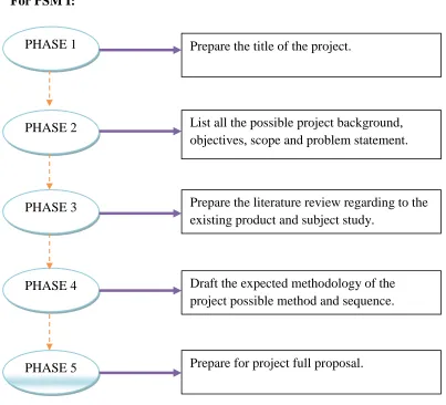
For PSM I:
Figure 1.4: Flow Chart of PSM I
PHASE 1 Prepare the title of the project.
PHASE 2
PHASE 5 PHASE 3
PHASE 4
List all the possible project background, objectives, scope and problem statement.
Prepare the literature review regarding to the existing product and subject study.
Draft the expected methodology of the project possible method and sequence.
7
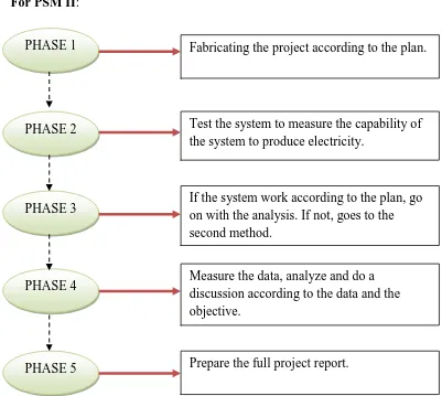
For PSM II:
Figure 1.5: Flow Chart of PSM II
PHASE 1 Fabricating the project according to the plan.
PHASE 2
PHASE 5 PHASE 3
PHASE 4
Test the system to measure the capability of the system to produce electricity.
If the system work according to the plan, go on with the analysis. If not, goes to the second method.
Measure the data, analyze and do a discussion according to the data and the objective.
8
CHAPTER II
LITERATURE REVIEW
2.1 Introduction to Water Turbine System
2.1.1 History of Water Turbine System
Water turbine had been used for over centuries to convert freely available mechanical energy from rivers into useful mechanical work, usually through a rotating
shaft. Water turbines mean a rotary engine that takes energy from moving water. Before the engines been invented, it is known as water wheels. Water wheels is a machine which converting the energy of flowing of falling water into more useful forms of power. It is quite same with the water turbines and it only differs at the engine part. The water wheels didn’t have engine install in the system but the water turbines does have.