i
WORKER HEALTH MONITORING SYSTEM BASED ON SOCSO STANDARD
LIM CHOON PIN
This Report Is Submitted In Partial Fulfillment Of Requirements For The Bachelor Degree of Electronic Engineering (Computer Engineering)
Fakulti Kejuruteraan Elektronik dan Kejuruteraan Komputer Universiti Teknikal Malaysia Melaka
iii
“Saya akui laporan ini adalah hasil kerja saya sendiri kecuali ringkasan dan petikan yang tiaptiap satunya telah saya jelaskan sumbernya.”
iv
“Saya/kami akui bahawa saya telah membaca karya ini pada pandangan saya/kami karya ini adalah memadai dari skop dan kualiti untuk tujuan penganugerahan Ijazah Sarjana
Muda Kejuruteraan Elektronik (Electronic Engineering).”
v
vi
ACKNOWLEDGEMENT
First of all, I would like to express my special thanks of gratitude to my lecturer, Dr. Syafeeza as well as our Dean, Dr. NurulFajar, who gave me the golden opportunity to focus on this wonderful project topic, Worker Health Monitoring System. They also helped me in a lot of research, I came to know about so many new things, and I am thankful to them.
Secondly, I would also like to thank my parents. They support me by giving compliment when I success and not to give up when overcome with problems. They also give a lot of support in term of physically and mentally.
vii
ABSTRACT
viii
ABSTRAK
ix
TABLE OF CONTENT
BAB CONTENT PAGE
PROJECT TITLE i
RECOGNITION ii
DEDICATION v
ACKNOWLEDGEMENT vi
ABSTACT vii
ABSTRAK viii
TABLE OF CONTENT ix
LIST OF TABLE xiv
LIST OF FIGURE xv
LIST OF ABBREVIATION xviii
I INTRODUCTION 1
1.1 BACKGROUND 1
1.2 PROBLEM STATEMENT 2
1.3 OBJECTIVE 2
1.4 SCOPE OF PROJECT 2
1.5 SIGNIFICANCE OF PROJECT 3
x
II LITERATURE REVIEW 5
2.1 Database in PERKESO 5
2.1.1 Work Rehabilitation 5
2.1.2 Type of Training 6
2.1.3 Training Equipment 8
2.2 Type of training equipment in Rehab Centre 8 2.2.1 External Knee Adduction Moment on Elliptical Trainer 8 2.2.2 Digital motion using arm and wrist sensor 9
2.2.3 Game based home rehabilitation 9
2.2.4 Virtual Reality with Robot Therapies 10
2.3 System Operation of monitoring system 11
2.3.1 External Knee Adduction Moment on Elliptical Trainer 11 2.3.2 Digital motion using arm and wrist sensor 11
2.3.2 Game based home rehabilitation 12
2.3.3 Virtual Reality with Robot Therapies 14
2.3.3.1 The middleware RehabConnex 14
2.3.3.3 Lokomat 14
2.3.3.4 ChARMin 15
2.3.3.5 PITS Glove 15
2.3.3.6 Color Tracking 15
xi
2.3.3.8 Type of Rehab Games 16
2.4 Description of physical test 17
2.4.1 External Knee Adduction Moment on Elliptical Trainer 17 2.4.2 Digital motion using arm and wrist sensor 17
2.4.3 Game based home rehabilitation 18
2.4.4.1The rule of game 18
2.4.4.2 Game Selection 19
2.4.4 Rehab Game with Robot Therapies 19
2.5 Summary of Literature Review 21
III METHODOLOGY 22
3.1 Flow Chart 22
3.2 Data Collection from PERKESO 24
3.3 Circuit Design Based on equipment of Rehab Centre 24
3.3.1 Multiplexer 24
3.3.2 Connector 25
3.3.3 Resistor 25
3.3.4 Arduino Platform 26
3.4 Simulation of circuit using ISIS 26
3.5 PCB fabrication process 29
3.5.1 ARES Schematic layout 29
xii
3.5.3 Etching 31
3.5.4 Drilling 31
3.5.5 Troubleshoot 32
3.6 Create platform to link between hardware and software 32
3.7 Create graphical user interface (GUI) 33
3.7.1 Login Page 33
3.7.2 Reading data from COM port 33
3.7.3 Calculate transition time of rod 34
3.7.4 Graph of Time Vs Rod 34
IV RESULT AND DISCUSSION 36
4.1 Circuit Design 36
4.2 Arduino Software 38
4.3 Integrate hardware with Arduino 41
4.4 Shift register circuit 42
4.5 Visual Basic software 43
4.5.1 Login Page 43
4.5.2 Selection of Test 44
4.5.3 Connection of Serial Port 45
4.5.4 Transition time of rod 46
4.5.5 Real time LED display 47
xiii
4.5.7 Output Graph 48
4.5.8 Overview of GUI 49
4.6 Combining hardware with software 50
V CONCLUSION AND RECOMMENDATION 52
5.1 CONCLUSION 52
5.2 FURTHER RECOMMENDATION 53
xiv
LIST OF TABLE
Table 2.1 Type of test and position of rod transition 6 Table 2.2 Number of Repetition and Time limit for test 7
Table 2.3 Comparison between other equipment 21
xv
LIST OF FIGURES
Figure 2.1 Equipment in Rehab Centre 8
Figure 2.2 A modified elliptical trainer 9
Figure 2.3 Lokomat 10
Figure 2.4 Version 1 Experiment testing using laptop 12 Figure 2.5 Version 2 Experiment testing using Mobile 12
Figure 2.6 Kinect Xbox 360 13
Figure 2.7 Pulse oximeter 13
Figure 2.8 Elbow flexion 17
Figure 2.9 Shoulder flexion 18
Figure 2.10 Gabarello v1.0 and v2.0 19
Figure 3.1 Flow Chart 23
Figure 3.2 Shift Register 74LS165 25
Figure 3.3 pin-37 connector 25
Figure 3.4 Resistor 330ohm 26
Figure 3.5 Arduino Mega 2560 26
Figure 3.6 Arduino schematic library 27
Figure 3.7 Arduino preference 27
Figure 3.8 Hex file location 27
Figure 3.9 Arduino Component Properties 28
Figure 3.10 Virtual Terminal 28
xvi
Figure 3.12 ISIS schematic diagram 29
Figure 3.13 ARES design 30
Figure 3.14 UV light exposition 30
Figure 3.15 Etching solution 31
Figure 3.16 Drilling machine 31
Figure 3.17 Circuit Diagram before troubleshoot 32
Figure 3.18 Project title with Rehab Centre 32
Figure 3.19 Serial Port 33
Figure 3.20 Led picture box 33
Figure 3.21 Timer Icon 34
Figure 3.22 Graphical Output 35
Figure 4.1 Soldering on each pin 37
Figure 4.2 ISIS simulation of circuit 37
Figure 4.3 Pin number and pin mode 38
Figure 4.4 Initialization of clockPin and latchPin 38
Figure 4.5 Read_data( ) function 39
Figure 4.6 The function of compare previous data and current data 40
Figure 4.7 Display_data( ) function 40
Figure 4.8 Output of serial monitor 40
Figure 4.9 Arduino Mega in ISIS 41
Figure 4.10 Connection of schematic diagram 42
Figure 4.11 Hardware circuit for demonstration 42
Figure 4.12 Login page of GUI 43
xvii
Figure 4.14 Welcoming Message 44
Figure 4.15 Selection of test 44
Figure 4.16 Axial Rotation test 45
Figure 4.17 Serial port connection 45
Figure 4.18 The code of open serial port 46
Figure 4.19 Real Time led display 47
Figure 4.20 Repetition Completed 48
Figure 4.21 Status of patient 48
Figure 4.22 Graph of Time vs Rod Number 49
Figure 4.23 Graph of each repetition 49
Figure 4.24 Overview of GUI interface 50
Figure 4.25 Overall project 50
xviii
LIST OF ABBREVIATION
Acronym Definition
PERKESO Pertubuhan Keselamatan Sosial Malaysia SOCSO Social Security Organization
EKAM External Knee Adduction Moment ET Elliptical Trainer
PT Physical Therapy
IMU Inertial Measurement Unit UG Universal Goniometer
ASSESSOR Assistive Sensor Suite for Sports and Rehabilitation IMIC Innovative Movement Therapy in Childhood GUI Graphical User Interface
VR Virtual Reality
PITS Pediatric Interactive Therapy System ISIS Intelligent Schematic Input System ARES Advanced Routing and Editing Software PCB Printed Circuit Board
1
CHAPTER 1
INTRODUCTION
1
1.1 Background
2
1.2 Problem statement
There are a few problems arise from this equipment in which it produces inaccurate results. Many types of error will easily occur during human observation when they need to observe the shifting rod process thoroughly. The equipment in Rehab Centre need human intervention such as to start and stop the timing of observing the patient task. Nevertheless, this equipment also requires a lot of human effort due to a large amount of training equipment. In my opinion, the human resources should be saved and use it for other more important matter. Moreover, these equipment are lack of information that use to display their performances.
1.3 Objectives
The aim of this project is to provide an autonomous system for PERKESO Company and reduce their work and further enhance the accuracy of the equipment. Therefore, the objectives of the project are listed below:
i) To save human resources and to replace the original equipment with an automated system.
ii) To calculate the average transition time of rod between zones. iii) To improve the accuracy of the equipment and avoid human error.
1.4 Scope of project
This project is focusing more on increasing the functionality of the original equipment by using a hardware prototype and Visual Basic as the software medium.
Arduino is used to connect both hardware prototype and Visual Basic to process the output.
Secondly, this project only focuses on how to display the current 15-rod position on Visual Basic and display error when patient transfer the rod to the wrong position.
3
be compared with the time that is set by SOCSO standard and determine the status of the patient.
1.5 Significance of project
The aim of this project is to helpRehab Centre to save their human resources and enable them to focus on other important tasks. Instead of using human resources, everything is autonomous by using Visual Basic through Arduino platforms and this system is a real-time recording system. The patient can use this equipment to their ability anytime without the help of the worker of PERKESO. This real-time system has greatly increases the accuracy up to 0.1 seconds of recording the transition time of the shifting rod process, Visual Basic also display the graphical output, which is easier to compare between the transitions of each rod process. These time transition of the rod is undeniable proof for the operator of PERKESO to know the ability of the patient. With these advantages, the system is not only fast and accurate, but it also improves the efficiency of PERKESO Company.
1.6 Thesis outline
Chapter 1 presents the introduction of the project. A simple explanation of this project will be written here. It also includes the background, problem statement, objectives, scope of the project and the thesis outline of the project.
Chapter 2 presents the basic theory of shift register, Arduino and also Visual Basic. The theory will include on how to display information on Visual Basic and how to connect all of this hardware through Arduino platform. Each of the theory will be proven by doing a literature review and further improvement from it.
Chapter 3 presents the methodology part of the project. Flow chart of the project and procedure will be presented in this chapter along with a description.
4
5
CHAPTER 2
LITERATURE REVIEW
2
This chapter will briefly discuss all the related research of several Rehab Centre and how they improve the life of the patients. Database of the current project is also included in the literature review.
2.1 Database in PERKESO
2.1.1 Work rehabilitation
Work rehabilitation is a structured program of improving physical strength of condition exercise and functional task either with real or simulated job activities. They provide a transition between acute care and return to work while addressing the safety issues, physical tolerance, work behavior and abilities.
6
They provide services such as pain management, work capacity such function capacity evaluation, cognitive function evaluation, and work simulated evaluation.
Firstly, they analyze the job or occupation by identifying risk factor and provide a recommendation for changes to the physical layout of the workstation. Next, they organized a return to work program by identifying or modifying tasks and come out with a suitable plan to facilitate a smooth and timely return to work. They also provide work injury prevention services by educating their employees to help them to understand their responsibilities for prevention of work injuries. Lastly, they also provide work counselling by identifying employee work interests as well as their strength and weakness.
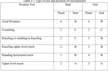
2.1.2 Type of training test
Table 2.1 shows the type of test which taken from PERKESO Rehab Centre. There are many different types that did not include into the table since it is out of the scope. Table 2.2 above show the repetition and time limit; each test has a different time limit and repetition due to the distance of the panel to panel.
Table 2.1 Type of test and position of rod transition
Position Test Start End
Panel Start Panel End
Axial Rotation 6 B 4 B
Crouching 2 C 3 C
Kneeling to standing to kneeling 2 C 3 B
Kneeling upper level reach 2 B 3 B
Standing horizontal reach 1 B 4 B