1 23
Journal of Sol-Gel Science and
Technology
ISSN 0928-0707
Volume 73
Number 2
J Sol-Gel Sci Technol (2015) 73:484-500
DOI 10.1007/s10971-014-3600-5
synthesized by solution process: towards
efficient carbon nanotube growth
Mohd Asyadi Azam, Nor Najihah
1 23
R E V I E W P A P E R
Systematic review of catalyst nanoparticles synthesized
by solution process: towards efficient carbon nanotube growth
Mohd Asyadi Azam•Nor Najihah Zulkapli •
Zulhilmi Mohamed Nawi• Nik Mohamad Azren
Received: 26 September 2014 / Accepted: 11 December 2014 / Published online: 24 December 2014
Springer Science+Business Media New York 2014
Abstract Nano-field research has been expanded rapidly since those tiny materials such as carbon nanotubes (CNTs), cobalt catalyst and iron catalyst can give huge impact to the application products with their extraordinary properties. The scientific discovery of these materials can be defined as a magic key to solve the raw materials shortage and unlock the limitation performance of the devices. CNTs have been found to be one of the new nanomaterials that can improve different kind of devices’ performance. CNT can be grown on the substrates with the presence of active metal catalysts. Since small metal cat-alyst particles (diameter\10 nm) are crucial in growing
CNTs, the deposition method of metal catalyst on the substrates has been studied. The optional processes using solutions to produce catalyst nanoparticles will be dis-cussed in this review. Sol–gel process along with spin coating is the most suitable deposition method with low cost of production and the easiness to control particle size deposited on the substrates.
Keywords Carbon nanotube Metal catalyst NanoparticlesSol–gel processSpin coating
1 Introduction
Nowadays, people are talking about nanotechnology in all fields of studies such as sciences, engineering, medicine,
etc. Nanotechnology is all about producing, manipulating small objects and building from objects that are extremely small which is less than 100 nm. There are several advantages in economic and technology by making things smaller such as the cost of production will be reduced by a mass production when the materials or things getting smaller. The quantity of materials used for the production also can be cut-off due to the extraordinary properties of the nanomaterials themselves. Thus, the shortage of nat-ure’s sources could be solved accordingly.
1.1 What is CNT?
Carbon nanotube (CNT) is just tiny structures in nano-scales in which the diameter is about 10,000 times smaller than human hair but they have huge impact on science and technology. They have been rapidly known by the people in the world ever since Sumio Iijima had been published his research in 1991 [1] and exposed the unique structural and properties of CNTs to the world. His invention often cited in most of the published paper on the topic of carbon nanotubes. However, he was not the first person who dis-covered these allotropes of carbon because CNTs had been observed prior to his invention by many researchers since 1952 until 1989 [2–18]. Basically, carbon nanotubes are formed from a repeated chemical element of carbon (C) in which bonded by covalent bonding. Covalent bonding is a strong chemical bond that involves in sharing electron pairs between atoms. The most well-known allotropes of carbon are 2D-graphite, 3D-diamond, and amorphous carbon. Graphite has been widely used as the cores of pencils after lead because lead has poisonous issue back then. Diamond is the hardest nature material known because it is arranged in diamond lattice. The highest hardness own by this structure leads to the restructured as synthetic diamond to
M. A. Azam (&)N. N. ZulkapliZ. M. NawiN. M. Azren
Carbon Research Technology Research Group, Faculty of Manufacturing Engineering, Universiti Teknikal Malaysia Melaka, Hang Tuah Jaya, 76100 Durian Tunggal, Melaka, Malaysia
be used in industrial application like cutting and polishing tools. Another form of carbon is 0D-fullerene that has been discovered by Kroto [19]. Hence, based on that finding, nanotubes can be classified as one of the fullerence’s family member.
CNTs can be classified based on the helicity and the direction of CNT growth. There are two famous types of carbon nanotubes related to helicities found in the research field such as single-walled CNT (SWCNT) and multi-walled CNT (MWCNT) [20]. SWCNT structure is like wrapping a 2D-graphene sheet into a seamless cylindrical structure or by elongating a Bulkyball or C60to be a tubular
structure [21–23]. There are three ways of graphene sheet is wrapped which are zigzag, armchair and chiral. Different ways of wrapping will promote different properties in which can be used in various application. Meanwhile, MWCNT structure is quite similar to the SWCNT but the different is only that it consists of multiple rolled layers of graphene. However, SWCNT has been a spot interest because of its physical properties. CNTs can be grown entangle or align. Aligned CNT in which can be used to improve the device performance is divided into two pat-terns; vertically and horizontally [24–26]. These two pat-terns can be tailored by controlling several parameters especially during the catalyst preparation and CNT growth process in which will be discussed further in the next section.
1.2 CNT growth
CNT growth is the most important process in order to produce high quality of CNT. In order to grow the CNT, there are three main materials needed to achieve the goal which are catalyst, substrate, and carbon sources. Those ‘ingredient’ is like the concept of planting a tree. Without the seed, soil, water and sunlight, tree cannot be grown. It is the same goes to CNT growth. Without the main mate-rials, the CNT cannot be grown out of nowhere. In addi-tion, the CNT growth process selection is also crucial. There are several processes that have been used by the researchers up to this century in which will be elaborated later. Moreover, along with the catalyst preparation and CNT growth stages, there are also several parameters that are needed to take into account.
1.2.1 Catalysts selection
Catalyst selection is one of the most important things towards a good result of CNT production. With proper selection of materials and good control of particle size of catalyst, the desired type, quality and characteristics of CNT can be achieved. Transition metals are the most effective catalyst to grow CNT on substrate especially iron
(Fe), cobalt (Co) and nickel (Ni) [27]. These metals have high solubility of carbon at high temperature and high diffusion rate in which very helpful during the CNT growth process. Moreover, the melting point for those catalyst candidates is suitable to grow CNT since the growing temperature is in range of 700–900C [28]. They also have
stronger adhesion with the CNT produced at the end of the process and potential in forming high curvature of CNT. Back then, the CNT growths were carried out with different single metal catalysts (Fe, Co and Ni). Iron catalyst has potential to produce higher CNT deposit on the selected substrate due to high catalytic effect in hydrocarbon decomposition own by this metal but the CNTs were poorly graphitized [29]. Meanwhile, cobalt has the oppo-site effect on CNT growth found on iron catalyst. Thus, by combining these two metals means that the individual advantages are combined, hence it will improve the quality of CNTs. It was proved by Nakayama’s group that binary catalyst was able to grow CNTs and the study was suc-cessful at low temperatures [30]. In short, by combining more metal catalysts for CNT growth will give an inter-esting result but of course it will be more complicated.
Besides those metals, other metals in the same group such as Pt, Ag, Cu, and Pd are also potential in CNT growth [31–35]. Apart from transition metals, other metals which are known as new catalyst for CNT like Al, Mg, Sn, Cr, Mo and Mn are also very useful for CNT growth especially to grow horizontally-aligned SWCNT [24]. In order to produce aligned CNT, catalyst support is needed to be employed. The examples of catalyst supports that are commonly used are Al, Al–O, Al2O3, and SiO2 [36–41].
All the catalyst particles; main catalysts and catalysts support, are in nano-scaled, hence they need careful han-dling to make sure that they are attached well to the sub-strates. So, the route to synthesize catalyst nanoparticles is very crucial to determine the attachment ability of the catalyst to the substrate as well as to drive the quality of CNTs produced. There are many ways to synthesis nano-particles like wet chemical, mechanical, form-in-place and gas-phase processes. All these four methods will be dis-cussed further in the following sections.
1.2.2 Substrates selection
A good selection of catalyst should come with a good selection of substrate for CNT growth. There are many available substrates for CNT growth such as Si, SiO2, SUS
interaction with the selected catalyst in the direction of enhancing the growing process of CNTs. This interaction is related to the chemical bonding formation between these two things. A good chemical bonding of catalyst-substrate will help to avoid the detachment of catalyst particles from the substrate especially during the CNT growth process. Thus, it will lead to produce good quality of CNTs in straight direction.
In addition, good handling of substrate during the experiment is a must because substrate is a very sensitive product especially substrate with Si base like silicon and silicon oxide wafers. Si based substrates are quite brittle and easily breakup when dropped. Besides, the uniformity of catalyst thin film formed on the substrates during the deposition process could be affected by the uniformity of substrates’ surface. When there are scratches on the sub-strate, the uniform catalyst thin film is difficult to be achieved. Other factor that will lead to the failure of cat-alyst deposition process is the existence of impurities on the surface of substrates. Thus, cleaning process is needed before the catalyst deposition process. There are several methods for substrate cleaning. Substrates can be cleaned by piranha solution. This solution is a mixture of 1/1 (v/v) sulphuric acid and hydrogen peroxide. After 15 min of treatment by that solution, then substrates are rinsed with de-ionised water before the spin coater is used to dry them at speed of 8,000 rpm for 30 s [57]. Furthermore, sub-strates also can be cleaned with acetone by sonication process for 5 min. Then, just like the first method of cleaning, the substrates are washed with de-ionized water. Lastly, dry them with nitrogen gas [58]. The third sug-gestion of cleaning substrate is by acetone ultrasonic cleaning, followed by ultraviolet ozone cleaner treatment [59]. The last method is rinsed the substrates with acetone, subsequently treated by ethanol through sonication process for 10 min [60,61]. Proper cleaning will contribute to good
result of CNTs. Thus, proper selection of substrates cleaning method is very important.
1.2.3 CNT growth methods
CNT growth is the climax part of CNT growth process. There are three growth methods to produce CNTs such as arc discharge, laser ablation and chemical vapor deposi-tion. Other methods like pyrolysis, flame and liquid hydrocarbon synthesis also have been employed in this field but the scope is just up to laboratory level. These methods have their own contribution towards CNT growth. The differences of these methods are given in Table1.
Early of the CNTs discovery, arc discharge method has been used for the CNT growth purpose. It is a method where a direct-current arc voltage is applied across two graphite electrodes (\1 mm apart) immersed in an inert gas
such as He and Ar [63]. MWCNTs and SWCNTs can be produced through this method by the employment of pure graphite rods as cathode. MWCNTs will be deposited on the cathode by the deposition of fullerenes (as soot) inside the chamber. In 1992, the first CNT was obtained from this method; MWCNT. The dimension of the MWCNT was in micrometer length and the diameter was about 5–30 nm [64]. SWCNTs can be generated only with the existence of metal catalyst in graphite anode along with a pure graphite cathode. The first SWCNT was produced in 1993 [65]. However, defects have been detected on the produced CNTs. Thus, it was the start point where researchers have found laser ablation to improve the quality of the CNTs. Both methods have some similarities in terms of the pro-cessing principle; the evaporation of carbon solids gener-ates carbon atoms condensation. The difference is just on the source of heat needed to produce high temperatures, as the laser ablation used laser source and arc discharge used electric arc source. These sources lead to the high cost of
Table 1 Comparison of the available CNT growth methods [62]
Method Arc discharge Laser ablation Chemical vapor deposition Description Vaporization of carbon in the presence of catalyst under
reduced atmosphere of inert gas; formation of CNTs on electrodes during quenching
Vaporization of carbon target by laser; formation of CNTs on substrate during quenching
Formation of CNTs by
decomposition of hydrocarbons on catalyst nanoparticles Processing
parameters
Temp:[3,000C
Pressure: 50–7,600 Torr (under vacuum)
Temp:[3,000C
Pressure: 200–750 Torr (under vacuum)
Temp:\1,200C
Pressure: 760–7,600 Torr Advantages High quality of CNTs; MWCNT and SWCNT High quality of CNTs; SWCNT Flexibility of substrates; variety
forms of CNTs can be grown; mass production is possible Disadvantages Limited types of substrates; mass production is
difficult; expensive
Limited types of substrates; mass production is difficult; expensive
CNTs production and the mass production is quite difficult due to the ineffective cost for commercial purpose.
Then, the CNT technology has shifted to catalytic vapor deposition (CVD) method. This method is the solution for the cost problem of arc discharge and laser ablation methods. This is because the processing temperature nee-ded for CNT growth is low which is in range of 600–1,200C and the energy source to transfer energy to
gaseous carbon molecule is plasma or a resistively heated coil in ambient pressure [27,65,66]. CVD is a method of decomposition of hydrocarbon gases; methane, ethanol, carbon monoxide, acetylene, ethylene, etc., with the pres-ent of metal catalysts to grow CNTs in a tubular reactor [67]. There are five types of CVD available in this research world such as alcohol catalytic CVD (ACCVD), water-assisted CVD (WACVD), floating catalyst CVD (FCCVD), thermal CVD (TCVD) and plasma-enhanced CVD (PEC-VD) [21]. By controlling the processing parameter; tem-perature, pressure, gas flow rate, carbon feedstock, deposition time, reactor geometry and catalyst, the desired CNT structures can be tailored [28,68–70]. The function of catalyst to synthesize CNTs throughout the process is to enhance the nucleation of CNTs by reducing the activation energy, Ea, from carbon feedstock into reactive atomic carbon. The reactive carbon is then diffused towards the substrate to generate the CNTs by heating and coating with the transition metal catalyst like Fe, Co and Ni. In addition, the diameter of CNTs can be varied by varying the particle size of metal catalysts. Small diameter of CNTs will increase the device performance. Thus, to produce CNTs with small diameter (\10 nm), it is very important to select
the suitable process to synthesize catalysts nanoparticles. There are four routes to synthesize nanoparticles; wet chemical, mechanical, form-in-place and gas phase pro-cesses, in which will be discussed in the next section.
1.3 Four routes to synthesize nanoparticles
There are two different approaches to nanofabrication which are top-down and bottom-up [71]. Top-down approach is about breaking materials into basic blocks or structure. This kind of approach is time consuming, thus it is not suitable for large scale production since it is difficult to control the pro-cess and to get the narrow distribution of nanoparticles size. Lithography which is placed in form-in-place process is one of the examples for this approach. It can cause the crystal-lographic damage to the pattern itself. Other than that, mechanical process is also placed under the same approach meanwhile gas-phase process is classified under bottom-up approach. Bottom-up approach is a process of combining simple atomic level components to be a complex system. The simple components can be atom-by-atom, molecule-by-molecule or cluster-by-cluster. The desired products can be
achieved by this approach with some modification on the processing parameters such as temperatures, concentration and etc. The most interesting part is that it is an inexpensive process. Wet chemical process is a unique approach because it can be classified in both approaches and this process will be elaborated in details through the upcoming section.
1.3.1 Wet chemical processes
Wet chemical process is a process that involved in the reac-tion of two or more chemical solureac-tions under certain condi-tions and processing parameters [72]. It is the best method for production of nanoparticles especially to prepare catalyst nanoparticles for CNT growth because the homogeneity of the nanoparticles can be achieved from the molecular level design of the materials. Homogeneity of the solution is cru-cial due to achieve a good distribution and good uniformity of the deposited nanoparticles on substrates. Chemical pro-cesses also allow control of particles size and size distribu-tion, morphology and agglomerate size through single manipulation of the parameter [73]. Those parameters are important to determine nucleation, growth and coalescence of the nanoparticles themselves. Moreover, growth rate also another point that is needed to take into account because it will give huge effects on particle size, particle size distribu-tion, amount of crystallinity, crystal structure and degree of dispersion [73]. The growth rate can be controlled by con-trolling four factors; (1) concentration of reagents, (2) pro-cessing temperatures, (3) pH and (4) the order in which the reagents are added to the solution [73].
Furthermore, wet chemical process has three main types which are colloidal chemistry, hydrothermal and sol–gel methods. The additional types to this process are com-bustion and organized membranes method. Each method has their own suitable precursors, solvents and other materials such as surfactants in which will be discussed in details later. The advantages of this method compared to others are it is a simple technique, cheap; less instrumen-tation, and low temperature (\350C) synthesis [73]. It is
also able to produce large scale of production in variety of sizes and shapes. A wide variety of inorganic, organic and metallic nanoparticles can be fabricated through the wet chemical methods. Other than that, during the synthesis, it is possible for doping of foreign atoms (ions) into the process. Since it is able to convert the liquid form into dry powder or thin film easily especially sol–gel method, thus it has been suggested as the most suitable method to pre-pare metal catalysts for CNT growth.
1.3.2 Mechanical processes
two types of methods which are mechanical milling or attrition and mechanical alloying. Mechanical milling can be divided into two types; mechanical milling process and mechanochemical process. In mechanical milling process, the only happen is physical change of powder; single ele-ment or complex compound, in which the particles size is reduced. For example, the synthesis of CeO2nanopowder
uses a tungsten carbide ball-milling medium with toluene as a process control agent at 300 rpm for 10 h [74, 75]. Meanwhile, for the mechanochemical process, the chemi-cal reaction is happened. For example, by mixing ultrafine Si nanoparticles with graphite ball-mill, silica powders can be synthesized [76].
Mechanical milling process is a famous process to produce materials with nanocrystalline grain size. It is also the most productive method of producing large quantities of nanocrystalline powders from different materials such as metals, alloys, intermetallics, ceramics and composites. The objectives of this method are to reduce and change the particle size and shape, accordingly. Besides, for the mechanical alloying, it is aimed for mixing or blending of different materials to be a new phase and to synthesize nanocomposites. The minimum grain size obtainable by milling has been attributed to a balance between the defect/ dislocation structure introduced by the plastic deformation of milling and its recovery by thermal processes [77]. In order to avoid the contamination during the process, hydrogen or argon atmosphere has been preferred. Other than that, processing control agent; stearic acid and tolu-ene, also can be considered.
1.3.3 Form-in-place
Form-in-place process is a process that mainly aimed on the production of nanostructure layers and coatings. There are four examples of form-in-place process such as lithography, physical and chemical deposition and spray coating. Lithography method is usually employed in the microfabrication of integrated circuit (IC). It is more about patterning the microcircuit and most of the time this pro-cess contributes to wastage. Moreover, this method is quite expensive. For the physical and chemical deposition, they are usually seen to be used in CNT growth. Physical vapor deposition (PVD) is a neat method in which the uniform thickness of catalyst thin films and catalyst nanoparticles with the desired particle size can be obtained. However, this method also is quite expensive because it involves in high-temperature vacuum evaporation with subsequent condensation, or plasma sputter bombardment [78]. Thus, this method is not a cost effective method for the large scale of production. PVD consists of five variants which are cathodic arc, electron beam vapor, evaporative, pulsed laser and sputter depositions. All these methods have the
similarity to deposit thin film onto substrates except the source and procedures for the deposition. PVD coatings are usually harder and have high corrosive resistant as well as good impact strength. Since the process needs high tem-perature to be conducted, thus it is important to have a cooling water system to evacuate large heat loads.
Furthermore, chemical vapor deposition (CVD) has similarity with PVD which is based on deposition of vapor to deposit the thin films onto the substrates. However, the operating cost for this method much lower than PVD. This is due to the low processing temperature needed for the deposition process and the equipment is much simpler than the PVD one. It is also can produce high purity of products as good as PVD. Thus, this method is often to be used in most of the semiconductor industry. Besides, as stated in the previous section, CVD is one of the methods to produce CNT. For the CNT deposition, the carbon source is being used meanwhile for other deposition materials, other kinds of sources are employed according to the purposes. All of the stated methods classified under form-in-place process can be used to fabricate nanoparticles by scraping the deposits from the collector.
1.3.4 Gas-phase processes
Gas-phase process is a process that involved in precursors in gas form. Generally the processing temperature can reach up to several thousand Kelvin. High temperature is needed to generate nanoparticles from the vapor sources. The example of gas-phase process is flame pyrolysis or synthesis. Flame synthesis is a process that has been widely used in industry to produce carbon black and ceramic particles. It is a process of formation of molecular nuclei from either condensation or chemical reaction and sub-sequent growth by coalescence in high temperature region during the process. The generation of nanoparticles from the flame reactors is either from vapor or sprayed liquid precursors. Usually, the temperature of the flame can reach up to 2,500 K which is where the precursor gas phase will be decomposed [79]. Electro-explosion, laser ablation, high temperature evaporation and plasma synthesis are also included in the gas-phase processes [80].
2 Types of wet chemical routes
not in a thermodynamically stable state. They are in the state of ‘lonely’. Thus, they tend to make ‘friend’ with their ‘neighbors’. Then they started to agglomerate (growth stage). Agglomeration is a process that is needed to be avoided since it will affect the particles size and size distribution of the products. Hence, single nucleation event is necessary to prevent additional nucleation during the subsequent growth so that highly uniform nanocrystals can be formed.
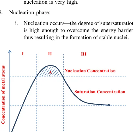
Since agglomeration is occurred when the nucleation and growth stages is happened at the same time, thus, it is possible to separate these two stages so that agglomeration can be avoided. LaMer and his friends has utilized a pro-cess called homogeneous nucleation to overcome this problem; LaMer concept [81]. In the homogeneous nucleation processes, nuclei appear in a homogeneous solution without any seed for heterogeneous nucleation. There exists a high energy barrier to nucleation because the system spontaneously changes from homogeneous phase to heterogeneous phase (liquid?nanocrystals). The LaMer diagram in Fig.1will show clearly how this energy barrier works to separate nucleation and growth stages.
The LaMer plot can be divided into three phases: A. Initiation phase:
i. The concentration of ‘monomer’ (the smallest subunit of the bulk crystal) increases continu-ously with time.
ii. The precipitation does not occur in phase I even under supersaturated conditions because the energy barrier for spontaneous homogenous nucleation is very high.
B. Nucleation phase:
i. Nucleation occurs—the degree of supersaturation is high enough to overcome the energy barrier, thus resulting in the formation of stable nuclei.
ii. Since the rate of monomer consumption result-ing from the nucleation and growth processes exceeds the rate of monomer supply, the mono-mer concentration decreases until it reaches the level at which the net nucleation is zero. iii. The ‘A’ label in the figure is indicated the
nucleation period.
C. Growth phase:
i. Below this level, the system enters the growth stage.
ii. The nucleation is effectively stopped and the particles keep growing as long as the solution is supersaturated.
2.1 Metal and intermetallic
Metal can be defined as a solid material (an element, compound, or alloy) that is hard, definite shape, shiny, and has good electrical and thermal conductivity. Metals are generally malleable, fusible and ductile. In the periodic table, 91 materials are metals. Meanwhile, intermetallic is a compound as solid phase consisting of two or more metallic elements, with optionally one or more nonmetallic elements has different structure form its constituents. The general method in synthesis of metal colloidal dispersions in order to obtained metal nanoparticles is reduction of metal complexes in dilute solutions [82]. By combining a low concentration of solute and polymeric monolayer (stabilizer) adhered onto the growth surfaces, the formation of metallic nanoparticles can be achieved. There are three main ‘ingredients’ for this type of chemical route; (1) precursors, (2) reduction reagents and (3) other chemicals (polymeric stabilizer or surfactants) (Table2; [83]).
Metal and intermetallic nanoparticles can be obtained by two methods; (1) aqueous method and (2) non-aqueous method. Both methods have quite similar chemical syn-thesis set-up except the solvent. Glass reactor chamber is usually used for the chemical reactions.
2.1.1 Aqueous method
Aqueous method is a method that used water as the solvent. As known, water is a good solvent for polar or ionic compounds and has been widely used as solvent system for most of the chemical solution reaction. This is due to the high permittivity of the water. Elemental metal nanoparti-cles for catalytic and biomedical application such as Au, Ag, Pt and Pd nanoparticles may be prepared by adding liquid reducing agents to aqueous solutions of respective salts in the presence of a stabilizer. For example, CdS nanoparticles has been synthesised by rapid mixing of
Saturation Concentration Nucleation Concentration
Concentration of metal atoms
III I II
A
Na2S and Cd(NO3)2•4H2O flow streams within a silicon/
glass micromixer based on the principle of flow lamination [84]. The stabilizer and reduction reagent used for this reaction were sodium polyphosphate and Na2S, accordingly.
The selection of reduction reagents for the process is crucial and it may affect the nucleation rate and particle growth which in turn influences the particle size and size distribution of the nanoparticles. Strong reduction reagents may lead to fast reaction rate and produce small particles. Meanwhile, for the selection of weak reduction reagents may induce a slow reaction rate and thus favors larger particles. In addition, slow reaction will tend to give two kinds of results which are wider and narrower size distri-bution of particles. For the wider size distridistri-bution, it leads to a continuous formation of new nuclei while for the narrower one; it will lead to diffusion-limited growth. Based on the comparison of average sizes of Au nano-particles in Table3, the reduction ability of citric acid is higher than sodium citrate. Since citric acid is a strong reduction reagent, thus the obtained particle size of Au nanoparticles is smaller than sodium citrate with the SEM result of 12.5 nm compared to 17.6 nm.
The suitable selection of polymer stabilizer or surfactant also should be made. It is employed to the reaction to form a monolayer on the surface of the nanoparticles. The addition of the stabilizer may help to prevent agglomera-tion of nanoparticles. Particle with smaller size has higher surface area and more reactive compared to the large one. Thus agglomeration is usually happened to these nano-particles. Hence, stabilizer is really needed. However, the presence of such polymer stabilizers during the formation of nanoparticle can have various influences on the growth process of nanoparticles. Interaction between the surface of a solid particle and polymer stabilizer may vary signifi-cantly depending on the surface chemistry of the solid, polymer, solvent and temperature. A strong adsorption of polymer stabilizers would occupy the growth sites and thus reduce the growth rate of nanoparticles while a full cov-erage of polymer stabilizer would hinder the diffusion of growth species from the surrounding solution to the surface of growing particle.
2.1.2 Non-aqueous method
Non-aqueous method or can be called polyol method is a method that needs no water as the solvent. Polyol is a short form for polyalcohol (e.g. ethylene glycol (EG), diethyl-eneglycol or 1,2 propanediol). The polyol will act as both reduction reagent and solvent. This non-aqueous may minimize the agglomeration and surface oxidation prob-lems. It is an ideal method for the preparation of larger nanoparticles with well-defined shapes (i.e. cubic, rod, etc.) and controlled particle sizes (various shapes). Elemental metal (Cu, Ni, Co, Pt, Co–Ni) and oxide particles can be obtained by this method. Since the employment of non-aqueous solvent only can minimize the agglomeration and oxidation problems, thus suitable stabilizer is needed for the reaction. Generally, PVP (Poly(vinylpyrrolidone) is used as the capping or stabilizing reagent owing to its excellent adsorption abilities [85]. In a typical polyol synthesis, the reduction of a metal salt was carried out by liquid polyol or diol in the presence of a stabilizing agent. The polyol method is basically conducted by adding precursor compound (oxides, nitrates and acetates) into a mixture of stabilizer dissolved in polyalcohol. Then, the mixture is heated (\200 C) in a certain duration of time.
For example, to obtain zinc oxide nanoparticles, a mixture of zinc(II) acetate with its polyalcohol and stabilizer was heated at 170 C for 30 min with constant stirring. When
the white suspension was obtained, then it was left over-night and centrifuged at 8,000 rpm for 20 min to separate the particles from the suspension [86]. The particles obtained should be rinsed with ethanol several times to remove the organic compounds and the stabilizer leftover. Then, Ar atmosphere is needed to dry the particles.
The advantage of polyol method compared to aqueous method is that this method results in the synthesis of metal nanoparticles protected by surface-adsorbed glycol, thus minimizing the problem of oxidation. Other than that, the use of non-aqueous solvent may help in reducing the problem of hydrolysis of fine metal particles that often occurs in the aqueous case. The products from this method have been widely used in several application such as the
Table 2 Summary of precursors, reduction reagents and polymer stabilizers [83]
Precursors Reduction reagents Polymer stabilizers Metal anode: Pd, Ni, Co Hydrogen (H2) Polymer stabilizers Palladium chloride (PdCl2) Sodium citrate (Na3C6H5O7) Poly(vinylpyrolidone), PVP
Hydrogen hexachloroplatinate IV (H2PtCl6) Hydroxylamine hydrochloride (NH4OH?HCl) Polyvinylalcohol, PVA
Potassium tetrachloroplatinate II (K2PtCl4) Citric acid (C6H8O7) Polyethyleneimine
Silver nitrate (AgNO3) Carbon monoxide (CO) Sodium polyphosphate
Silver tetraoxylchlorate (AgClO4) Phosphorus in ether (P) Sodium polyacrylate
use of Ag nanoaprticles in washing machine. It is called ‘Silver Wash’. Microscopic bits of electrolyzed silver (about 400 billion silver particulates) are dispersed and dissolved into the wash water, where they infiltrate fabrics on an almost molecular level. The silver nanoparticles kill 99.9 % of bacteria and fungi, says the manufacturer. Another example is in fresh box containers in which nat-urally kill bacteria and limit mold growth without toxins.
2.2 Hydrothermal
Hydrothermal is an important method for the synthesis and processing of advanced ceramics (structural and func-tional), catalysts, composites, alloys, intermetallic and nanomaterials from high temperatures aqueous solution at high vapor pressures. It is a non-conventional method to obtain nanocrystalline inorganic materials. Various inor-ganic materials can be prepared at temperatures substan-tially below those required traditional solid-state reactions. Moreover, the products obtained from hydrothermal method do not need post-annealing treatment and most of the time they are in crystalline structure. Thus, this may cut-off the cost of production.
As known, wet chemical route is involved in chemical reaction and hydrothermal also is not excluded from this reaction. The chemical reaction of hydrothermal is occur-red in water system at above ambient temperatures ([100C) with pressure during the heating more than 1
atmosphere. The maximum limits of the process may reach up to 1,000C and 500 MPa pressure [87]. Since the
required processing temperature and pressure is quite high, thus an autoclave is needed to withstand the processing condition for a long time. The autoclave also can provide a sealed or closed system. Hydrothermal process has a spe-cial type of chemical transport reaction because it depends
on liquid-phase transport of reactant for nucleus formation of the desired final products. The presence of water at elevated temperatures may help a lot for the precursor material transformation. Water is a common solvent in which will display different characteristics at different temperatures. For this case of process, the water can be an intermediate for the transformation of heat, pressure and precursor of the materials. The added chemicals compound also can be dissolved easily at the particular temperature. For certain cases, water also serve as the precipitating agent.
Hydrothermal method has five main parameters; (1) initial pH of the medium, (2) duration of synthesis, (3) temperatures of synthesis, (4) pressure of the system, and (5) concentration of reactants and additives. Those parameters may determine the processing space and thus influence reaction and crystallization kinetics. This process is occurred rapidly so that all precursors’ reaction will be finished within several hours in order to avoid a significant growth of the product particles. Moreover, high pressure is required to increase the solubility in the aqueous medium so that continuous crystal growth can be obtained. Thus, it leads to the non-ideal and non-equilibrium state to the reaction. By that, the solvent is always at its near-critical, critical or supercritical state. All these conditions may help for obtaining an effective reaction and hence produce a good result of particles formation.
A wide range of chemical compositions can be used to produce nanoparticles especially to produce ceramic nanoparticles. Most of the materials synthesized by this method are materials that cannot be obtained using clas-sical synthesis at high pressure. The most common oxide materials are ZrO2, TiO2, SiO2, ZnO, Fe2O3, Al2O3, CeO2,
SnO2, Sb2O5, Co3O4, HfO2, etc. The examples of complex
oxides are BaTiO3, SrTiO3, PZT, PbTiO3, KNbO3, KTaO3,
LiNbO3, tungstates, vanadates, molybdates, zeolites, etc.
[88]. Since the process needs simple equipment and low energy, thus this may leads to cost effective process. Even the autoclave is quite expensive, but with large scale of production, the cost effective still can be obtained. How-ever, it is agreed that it is impossible to observe the reac-tion process (black box).
2.3 Sol–gel
Sol–gel or chemical solution deposition is one of the wet chemical routes. Recently, this process has been widely used in the fields of materials science and ceramic engi-neering. Sol can be defined as a colloidal suspension of solid or macromolecular particles (1–1,000 nm in size) in a liquid. It has an unfixed shape in which the particles in the solid phase can move freely. Besides, gel is a porous 3-dimensionally interconnected solid network surrounding
by a continuous liquid medium (phase). It has a fixed shape. The particles in the solid phase are fixed in accor-dance with certain network structure and the movement is limited.
There are five steps in sol–gel process; (1) solution preparation, (2) sol stage (3) gel stage, (4) deposition technique and (5) heat treatment. In this process, there are two main ingredients should be presented which are pre-cursors and solvents. The suitable prepre-cursors and solvents for the desired product should be determined properly. The typical precursors for this process is from metal alkoxides and metal chlorides. However, metal alkoxides are much more favored because they readily undergo hydrolysis. The general chemical formula for metal alkoxides is [M(OR)n], where R is an alkyl group, inorganic or organic salts. Metal alkoxides require low processing temperature for fabrica-tion of nanomaterial with required phase selecfabrica-tion with correct stoichiometric ratio.
At the stage of preparing the precursor solution, the solid precursor will be dissolved in an organic solvent miscible with water or the reagent. Once the homogeneous solution is obtained, the solution will be converted to sol by the treatment with a suitable reagent. Hydrolysis reaction is occurred at this stage. It is a reaction in which metal alkoxide (M–OR) react with water to form metal hydroxide (M–OH). Normally, it takes several minutes to complete the reaction but it still depends on the types of metal precursors employed for this process. At the sol stage, the sol can be used to be transformed into thin films, powders, fibers and patterns. Thin films can be produced from sol by spin-coating, dip-coating, flow-coating and electro-deposition. While for the powder, it can be formed by spray-drying technique. Furthermore, fibers can be formed by electro-spinning, blow spinning, pulling-down and pull-ing-up techniques. For the patterns, many techniques can be used to fabricate the patterns such as UV patterning, electron-beam lithography, X-ray direct writing techniques and etc.
By allowing the sol to change into gel through polycon-densation, dense product, powders, monoliths, other forms can be produced. Condensation is a reaction which occurs when two metals hyroxides (M–OH?HO–M) combine to give a metal oxide species (M–O–M). The reaction forms one molecule of water. It is a process to induce the formation of small solids particles or cluster in a liquid (1–1,000 nm). Then, when the gel has been shaped to the finally desired shapes, the semi-products are going to heat treatment process in which to create a strong bonding between the particles and remove the solvent left in between particles.
2.4 Combustion
Besides hydrothermal method, combustion method also an important technique for the synthesis and processing of advanced ceramics, catalysts, composites, alloys,
intermetallic and nanomaterial. Combustion synthesis in solid-state chemistry is also known as metathesis reactions or self-propagating high-temperature synthesis (SHS) [89]. Generally, the high temperature is achieved not by placing the samples in a furnace but rather by using the heat generated by the exothermic chemical reaction itself. Combustion synthesis or combustion method can be char-acterized by fast-heating rates, high temperatures and short reaction times. Those indicators are quite similar to the hydrothermal except pressure used in hydrothermal method. There are two methods of combustion; (1) solid state combustion and (2) solution combustion.
Solution and solid state combustion has slightly differ-ent in terms of the initial form of precursors only. Solution state combustion is combustion of a mixture of solvent and precursor in a chamber. Generally, the mixture is brought to boils until it ignites. Once the self-sustaining and rather fast combustion reaction occurs, a dry, crystalline and fine oxide powder will be produced. The common metal pre-cursor used is metal nitrate due to its high oxidization ability. The source to ignite the combustion process is organic fuel (glycine, urea, carbohydrazide or citric acid); reducing agents). A strong exothermic reaction is occurred during the process in which leads to the formation of nanopowder at substantially lower temperature than otherwise required. Usually, the flames produced from the combustion can reach temperatures that exceed 1,500C
due to the large amount of gases formed at initial [90]. Frequently, nitrates are chosen as metal precursors. This is because the NO3
-groups are oxidizing agents. This group also has high solubility in water, thus allows a suf-ficiently high solution concentration. Furthermore, organic compound has been favored as fuel for combustion. It is due to the high availability of the sources in the market and cheap. The most convenient fuel is urea. The organic fuel is the source of C and H which in combustion the CO2and
H2O will be formed for heat releasing. They are also
formed complexes with metal ions facilitating homoge-neous mixing of the cations in solution.
2.5 Nanoparticles via organized membranes
Basically, there are three types of micelles; (1) normal micelle, (2) reverse micelle and (3) bilayer lamella (Table4). The hydrophobic hydrocarbon chains of normal micelle are towards the interior of the micelle and leaving the hydrophilic groups in contact with aqueous medium. While for the reversed micelle, it is formed in non-aqueous medium in which the hydrophilic groups faced towards the interior of micelle. Normally, most of the precursors used are easily dissolved in water medium compared to oil medium. Thus, reversed micelle has been used widely rather than normal micelle. Surfactants as self-assembled structures can act as reactor chambers to synthesis nano-particles by controlling particle nucleation, growth, size and shape of the particles (in a confine space). In this synthesis, the reaction is done only inside the micelle in which the available reactant is in the desired amount. When the reactants are completely consumed, the process will be automatically terminated.
As shown in Fig.2, the amphipathic or surfactant structure consists of two parts; (1) head: hydrophilic and (2) tail: hydrophobic. They are usually self-assemble at air/ aqueous solution or hydrocarbon/aqueous solution inter-face when the surfactants are dissolved into a solvent (water or oil). Then the hydrophilic part is turned towards the aqueous solution. Micelle will be formed when the concentration of the surfactants or block polymers exceeds a critical level. The surfactant will reside at the interface separating hydrocarbon and aqueous solution. These interactions allow the molecules to self-assemble into membrane structure with minimum energy configuration. The micelle or microemulsion can be formed in two ways; (1) direct and (2) reverse. Direct reaction is happened when oil is dispersed in water, (o/w) colloidal system while the reverse reaction is vice versa. Direct reaction is a cost effective process and environmental friendly but limited precursor can react in oil core. However, reverse reaction has been intensively studied because various metal salts and organometallic compound can stay in aqueous solution through hydrolysis.
In order to prepare the nanoparticles, two microemul-sions are prepared separately by mixing each precursor
with surfactant, oil and water until the systems become homogeneous (transparent liquid). Then both microemul-sions are mixed together. During vigorous stirring, the micelles or reverse micelles collide with each other as a result of Brownian motion, which lead to the formation of transient dimers with oily or aqueous channel between two micelles or reverse micelles. The channels provide exchange opportunities of precursors in different micro-emulsions in which the exchange process determines the particle growth rate. After the breakup of dimers, the micelles or reverse micelles containing both precursors become independent nanoreactors in which the chemical reactions take place rapidly, thus leading to the nucleation of nanoparticles when reactants supersaturate the nanore-actors. The particles are either filtered or centrifuged and then washed with acetone and water to remove any residual oil and surfactant molecules adsorbed on the surface of nanoparticles. Subsequently, the powders are calcined to form the final product.
3 Flow of sol–gel (thin films formation)
3.1 Types of functional solutions
Thin film can be deposited on the selected substrates through sol–gel process [92]. As mentioned in Sect.2.3, thin films can be produced by spin-coating, dip-coating and etc. These techniques require catalyst solution to achieve the desired deposition products. Alcoholic solution con-taining metal salts is the most common catalyst solution [25,93,94]. Alcohol is one type of solvent that can dilute the metal salts well (i.e. methanol, ethanol). It is also has high volatility in which very helpful in the formation of thin film during the deposition process. Among the avail-able metal catalyst solution, metal nitrate and metal acetate
Head : hydrophilic
Tail: hydrophobic
Fig. 2 Schematic diagram of amphipathic structure
Table 4 Types of micelles [91]
Types Structures Sizes Spherical/normal
micelle
3–6 nm
Reverse micelle 3–6 nm
have been favored as the catalyst precursors due to their high solubility in alcohol (Table5).
3.2 Thin film preparation
3.2.1 Spin coating
Spin coating has been widely used in microelectronics industry to produce photoresists; the thickness typically in micron range. This process is one of the famous processes for thin film deposition such as electrodeposition [107], spray pyrolysis [108], chemical bath deposition and dip coating technique [59]. However, the thin film production in nano range which is less than 100 nm is still remained largely unexplored. Thin films (\100 nm) is favored for
catalyst thin films for the purpose of CNT growth. It is expected that if that thickness of film is achieved, the particles will be formed in the size of several nano-meter. It is also expected that the CNT grown on the particles will have the same or less diameter as the catalyst particles. Since spin coating has a potential to control the thickness of thin films by controlling the spin speed, spin duration and angular acceleration, thus, this method has been started to be explored [109,110].
The principle of spin coating method is basically the solution precursor (metal precursors dissolved into solvent) is deposited on the cleaned substrate. According to a group of researchers, the substrate is rapidly accelerated accord-ing to the desired spinnaccord-ing rate [111]. During the spinning process, due to the centrifugal force, the deposited solution flows radially and it cause the excess is executed of the edge of substrate. This phenomenon will cause the depos-ited solution to form thin film when the equilibrium thickness is obtained due to solvent evaporation [111,112]. The mathematical modeling also can be used to explain the principle of spin coating process and modify the controlled parameter in order to obtain the desired thickness of thin films. However, it is not covered in this area of discussion. The spin coating process is basically consists of four steps, as illustrated in Fig.3.
a. Solution dropping: The catalyst precursor dissolved in solvent is dropped on the center of the cleaned substrate, initially at rest.
b. Spin-up: The centrifugal force allows the deposited solution to flow radially on the substrates.
c. Spin-off: The excess solution at the edge of the substrate is executed in drops and leads to thin the film layer. The execution of the excess solution is decreas-ing throughout this step because as the thickness of the layer is decreased, the viscosity of the solution will be increased due to the high flow resistance.
d. Evaporation: It occurs along the spinning process to remove the solvent and thinning the film especially during the spin-off step till the end.
By depositing a colloidal solution (a mixture of PEG-400-ethanol-iron nitrate) dissolved in 50 % ethanol on a 15 mm2 of silicon wafer (1,000 A˚ thermal oxide layer) with the spinning condition of 8,000 rpm spin speed, 30 s spin duration and 300 rpm/s angular acceleration, a group of researchers was able to obtain a uniform size distribution of iron particles with the average particle size of 5.08 nm [57, 95]. They were also able to confirm the SWCNT growth on the thin film from the obtained intensity ratio of the G- to D-band (IG/ID) of Raman spectrum with the
average ratio of over 10. Meanwhile, when the spin speed used was 5,000 rpm, the size of cobalt catalyst particles obtained was 14 nm [113]. It shows that the selection of spin speed will affect the size of particles formation. It is also found that the spin duration of 30 s has been used frequently in this area of research [57, 95, 114]. Hence, proper selection of the parameter is very crucial to deter-mine the size of catalyst particles.
Table 5 Summary of metal nitrates and metal acetates for CNT growth
Functional solution Metals Type of CNT Ref Nitrates (NO3
-) Fe SWNTs [95,96] Nitrates (NO3
-) Co SWNTs [97,98] Nitrates (NO3
-) Ni MWNTs [99,100] Acetates (C2H3O2
-) Fe MWNTs [101] Acetates (C2H3O2
-) Co Aligned-SWNTs [102–105] Acetates (C2H3O2
-) Ni MWNTs [106]
ω
ω
(d
ω
/dt)
≠
0
(a) (b)
(c) (d)
3.2.2 Dip coating
Dip coating is an ideal technique for the translation sym-metric substrates. The process is simply placed the sub-strate in the solution and by controlling the velocity (usually constant), the film is uniformly covered the immerged surface during the withdrawn substrate from the solution. This film is left drying for some minutes to allow the sol–gel transition to take place. The available withdraw velocities are from 1 up to 50 cm min-1
. The film thick-ness increases with increasing withdrawal rate and for a given withdrawal speed the film thickness increases with an increase in oxide content. The thickness coating by this process is usually in range of 50–500 nm. The thickness can be calculated by the Landau–Levich equation [115]. The steps involved in dip coating process are illustrated in Fig.4.
h¼ ðgtÞ
2=3
c1LV=6ðqgÞ1=2 ð1Þ
h=coating thickness;v=viscosity;cLV =liquid–vapour
surface tension;q =density;g=gravity.
The uniformity of the thin film produced by this process can be controlled. However, the process is quite slow compared to spin coating process. A film layer with the thickness of 96 nm has been obtained from the deposition of solution (cobalt acetate tetrahydrate and ethanol) by dip coating with speed of 4 cm/min [58]. In other paper, the same drawing speed has been used and the coated substrate has been successfully grown the SWCNTs with the diam-eter range of 0.8–1.4 nm [59].
3.3 Heat treatment
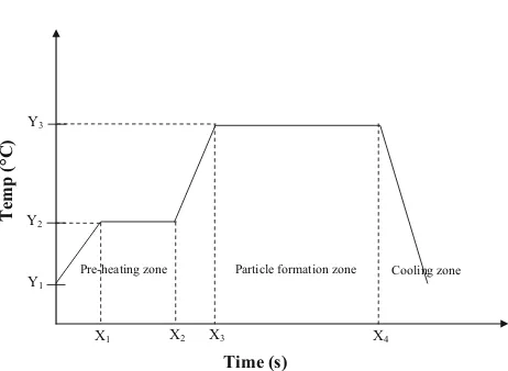
Heat treatment is the final step for catalyst particles for-mation. It is a heating and cooling process in which will
turn the thin film form into particles form. There are sev-eral parameters that will affect the size of catalyst particles. Since the small particle size is very important towards CNT growth, thus every factor that will affect the value is taken into concern. For the analysis purpose of the uniformity of catalyst distribution along the substrate surface, it is helpful to compare the roughness value with the average film thickness. If the roughness is considerably smaller than the thickness, the catalyst film is likely to be continuous. The quality of the thin films by sol–gel spin coating process and crystallization was influenced by heating temperature [116]. Magnetic elements, such as iron, have a strong tendency to combine at high temperatures because of their magnetic properties and their high specific surface energy [117]. The particles that were close to each other coalesced, forming larger particles with an elliptical shape [57].
The stability and the uniformity of the cluster play an important role in formation of CNTs and also their prop-erties. Cluster combines at high temperature of reduction or oxidation and reaction when salt are treated to obtain the metal catalyst [118]. With the suitable temperature, the large agglomeration of iron salt can be prevented. The diameter of CNTs could be controlled directly by the size of the catalytic nanoparticles [119]. During the particles formation, the surface cracks opened up and expanded to a larger size, meanwhile, the widths of cracks increased with increased temperature. Then, after heat treatment, the sur-faces of the splats became rougher with formation of new tiny particles. The roughness of particles increased with increased temperature. Cracks widening might be related to the volume change associated with the transformation of amorphous to crystalline, changing a loose packed amor-phous structure to a close packed crystalline structure [120]. The illustration of heat treatment process is shown in Fig.5.
Dipping Wet layer formation Evaporation
Fig. 4 Stages of the dip coating process
Temp (°C)
Time (s)
X3 X4
Y1
Y2
Y3
X1 X2
Pre-heating zone Particle formation zone Cooling zone
Table 6 Summary of analysis on cobalt and iron catalyst
Methods Description Findings Ref XRD Using Cu Karadiation
(k=1.5406 A˚ )
The average particle sizes of Co3O4thin film were calculated
using the full width at half maximum (FWHM) of (311) peak from the Scherrer’s method:
D¼Ck=bcosh
b: full width at half maximum D: crystallite size,
k: wave-length
C: correction factor=0.90
[103]
The phase purity of the samples is examined using Cu-Ka
radiation, 40 mA and 45 kV
XRD of SWNTs is characterized by a small relative intensity of the peak located at 2hequal 26.097
[58] SEM Model: JSM-6380
High resolution SEM operated at 20 kV in KSU
The resolution of the used SEM is not high enough to show the detailed features of the surfaces
[58] Model: JEOL-JSM-6360, Japan, operated at 20 kV The surface morphology for all films was nearly the same with
slight increase in grain size
The film surface looks smooth and composed of very fine elongated particles smaller than 80 nm in length connected by two–three spherical grains of about 40–45 nm in diameters Overgrowth of clusters is clearly seen
[103]
FESEM The study was performed using a Gemini LEO 1525 instrument operating at 15 kV
FESEM images of the CNTs grown on the wafer with five different absolute ethanol to PEG ratios and only diluted ethanol after 30 min of methane CVD
Dense CNT arrays were grown when colloidal solutions with 0, 25 and 50 % ethanol were applied
CNTs found were larger in diameter and carbon nanocapsules were visible when colloidal solutions
[119]
FESEM (ZEISS SUPRA 40) High aspect ratio nanostructures are observed on the two catalyst film surfaces
[121] TEM TEM investigation was carried out using a JEOL 2010F
operated at 200 kV and equipped with a Gatan imaging filter (GIF) system
Single-walled CNT was not found in the sample Too large catalyst particle to form single-walled CNTs Three kinds of multi-walled carbon morphologies were
observed:
Lengths from about 0.1 mm to a few microns,
Tipped with catalyst particles partially exposed to environment [122]
20 kV Tecnai-G2 F-20 model of FEI. Device resolution from 0.14 to 0.18 nm maximum thermal current is greater than 100 nA There is 0.5 nA or larger current in 1 nm probe.
The energy distribution is around 0.7 eV
CNT diameter is nearly 10 nm The appearance is darker in the picture.
The CNTs have diameters between 1.5–5 nm and also are transparent
[96]
AFM Scan size: 0.5, 1.0 and 2.0 mm.
Root mean square (rms) and peak-to-valley roughness values
The oxide surface roughness was measured to be quite small, not exceeding 0.1–0.2 nm
[123]
MPF3D Asylum Research with a cantilever (ArrowTM NC, Nanoworld) operated in the tapping mode. Scan rate: 1 Hz
Scan domains were varied from 292 to 191lm, while maintaining the resolution at 5129512
To evaluate the surface roughness
RMS value increases from 0.14 nm at 600C to 0.69 nm at
800C, indicating the presence of more nanoclusters on
surface after reduction at higher temperatures
3.4 Characterization method
There are many characterization methods can be employed to analyze the properties and morphology of the particles obtained. Surface morphology can be studied by scanning electron microscopy (SEM), field emission scanning elec-tron microscopy (FESEM) and transmission elecelec-tron microscopy (TEM). Besides, the particle size can be mea-sured either by the obtained morphology or X-ray diffraction (XRD). Commonly, the important information that is needed to measure and study is the particle size, particle distribution, uniformity and thickness of the thin film. Table6 summa-rized the analysis for cobalt and iron catalysts.
4 Summary
The optional processes to produce nanoparticles have been viewed. The available processes are wet chemical, mechanical, form-in-place and gas-phase. Out of those available processes, wet chemical process is the most suitable process to deposit the selected metal catalysts on the selected substrates for CNT growth purpose. Since the thickness of the deposited catalyst thin film is the matter of concern, thus spin coating is the most suitable method to achieve the desired thickness of thin films. The thickness of thin films is inversed to the spin speed, spin acceleration and duration of spin. The particles are formed during the heat treatment process. Hence, the pre-heating and heating temperature must be taken into account. The particle size and shape will be affected by the employed temperature. Since it is a cost effective process, perhaps the spin coating method can be used widely to deposit metal catalysts for CNT growth purpose. In conclusion, solution process is a good alternative technique for metal catalyst thin film deposition and particles formation towards CNT growth due to low cost of production, simple equipment, low energy consumption and can be conducted in ambient temperature.
Acknowledgments The authors gratefully acknowledged the financial support by the Ministry of Higher Education (MOE), Malaysia under the Exploratory Research Grant Scheme (ERGS) with research Grant Numbered E00032.
References
1. Iijima S (1991) Helical microtubules of graphitic carbon. Nature 354:56
2. Radushkevich LV, Lukyanovich VM (1952) On the carbon structure formed during thermal decomposition of carbon monoxide in the presence of iron (in Russian). Zh Fiz Khim 26:88
3. Tesner PA, Echeistova AI (1952) Investigation of the growth process of carbon-black particles by means of the electron microscope. Dokl Akad Nauk USSR 87:1029
4. Davis WR, Slawson RJ, Rigby GR (1953) An unusual form of carbon. Nature 171:756
5. Hofer LJE, Sterling E, McCartney JT (1955) Structure of the carbon deposited from carbon monoxide on iron, cobalt and nickel. J Phys Chem 59:1153
6. Walker PL, Rakszawski JF, Imperial GR (1959) Carbon for-mation from carbon monoxide–hydrogen mixtures over iron catalysts. J Phys Chem 63:133
7. Baird T, Fryer JR, Grant B (1971) Structure of fibrous carbon. Nature 233:329–330
8. Baird T, Fryer JR, Grant B (1974) Carbon formation on iron and nickel foils by hydrocarbon pyrolysis-reactions at 700C.
Car-bon 12:591
9. Baker RTK, Barber MA, Harris PS, Feates FS, Waite RJ (1972) Nucleation and growth of carbon deposits from the nickel cat-alyzed decomposition of acetylene. J Catal 26:51
10. Baker RTK, Harris PS, Thomas RB, Waite RJ (1973) Formation of filamentous carbon from iron, cobalt and chromium catalyzed decomposition of acetylene. Catalysis 30:86
11. Baker RTK, Waite RJ (1975) Formation of carbonaceous deposits from the platinum-iron catalyzed decomposition of acetylene. Catalysis 37:101
12. Koyama T, Endo M, Onuma Y (1972) Carbon fibers obtained by thermal decomposition of vaporized hydrocarbon. J Appl Phys 11:445
13. Oberlin A, Endo M, Koyama T (1976) Filamentous growth of carbon through benzene decomposition. J Cryst Growth 32:335 14. Baker RTK, Harris PS (1978) Chemistry and Physics of Carbon,
vol 14. Marcel Dekker, New York, p 83
15. Baker RTK (1989) Catalytic growth of carbon filaments. Carbon 27:315
16. Endo M (1988) Grow carbon fibres in the vapour phase. ChemTech 18:568
17. Dresselhaus MS, Dresselhaus G, Sugihara K, Spain IL, Gold-berg HA (1988) Graphite fibers and filaments, vol 5. Springer, Berlin, p 382
18. Speck JS, Endo M, Dresselhaus MS (1989) J Cryst Growth 94:834
19. Kroto H (2001) Fullerene science—a most international endeavor. J Mol Graph Model 19:187–188
20. Azam MA, Isomura K, Fujiwara A, Shimoda T (2011) Towards realization of high performance electrochemical device using vertical-aligned single-walled carbon nanotubes. Glob Eng Technol Rev 1:1–8
21. Azam MA, Manaf NSA, Talib E, Bistamam MSA (2013) Aligned carbon nanotube from catalytic chemical vapor depo-sition technique for energy storage device: a review. Ionics 19:1455–1476
22. Iijima S, Ichihashi T (1993) Single-shell carbon nanotubes of 1 nm diameter. Nature 363:603
23. Bethune DS, Kiang CH, Devries MS, Gorman G, Savoy R, Vazquez J, Beyers R (1993) Cobalt-catalysed growth of carbon nanotubes with single-atomic-layer walls. Nature 363:605–607 24. Yuan D, Ding L, Chu H, Feng Y, McNicholas TP, Liu J (2008)
Horizontally aligned single-walled carbon nanotube on quartz from a large variety of metal catalysts. Nano Lett 8:2576–2579 25. Murakami Y, Chiashi S, Miyauchi Y, Hu M, Ogura M, Okubo T et al (2004) Growth of vertically aligned single-walled carbon nanotube films on quartz substrates and their optical anisotropy. Chem Phys Lett 385:298–303
27. Kumar M, Ando Y (2010) Chemical vapor deposition of carbon nanotubes: a review on growth mechanism and mass production. J Nanosci Nanotechnol 10:3739–3758
28. Homma Y, Kobayashi Y, Ogino T, Takagi D, Ito R, Jung YJ, Ajayan PM (2003) Role of transition metal catalysts in single-walled carbon nanotube growth in chemical vapor deposition. J Phys Chem B 107:12161–12164
29. Hernadi K, Fonseca A, Nagy JB, Bernaerts D, Lucas AA (1996) Fe-catalyzed carbon nanotube formation. Carbon 34:1249–1257 30. Hernadi K, Fonseca A, Nagy JB, Bemaerts D, Fudala A, Lucas AA (1996) Catalytic synthesis of carbon nanotubes using zeolite support. Zeolites 17:416–423
31. He H, Gao C (2011) Synthesis of Fe3O4/Pt nanoparticles
dec-orated carbon nanotubes and their use as magnetically recycla-ble catalysts. J Nanomater 2011:1–10
32. Esconjauregui S, Whelan CM, Maex K (2009) The reasons why metals catalyze the nucleation and growth of carbon nanotubes and other carbon nanomorphologies. Carbon 47:659–669 33. Ding L, Tselev A, Wang JY, Yuan DN, Chu HB, McNicholas
TP, Li Y, Liu J (2009) Selective growth of well-aligned semi-conducting single-walled carbon nanotubes. Nano Lett 9:800–805
34. Ding L, Yuan DN, Liu J (2008) Growth of high-density parallel arrays of long single-walled carbon nanotubes on quartz sub-strates. J Am Chem Soc 130:5428–5429
35. Feng YY, Zhang HB, Hou Y, McNicholas TP, Yuan DN, Yang SW, Ding L, Feng W, Liu J (2008) Room temperature purifi-cation of few-walled carbon nano-tubes with high yield. ACS Nano 2:1634–1638
36. Liu X, Baronian KHR, Downard AJ (2009) Direct growth of vertically aligned carbon nanotubes on a planar carbon substrate by thermal chemical vapour deposition. Carbon 47:500–506 37. Azam MA, Fujiwara A, Shimoda T (2011) Direct growth of
vertically-aligned single-walled carbon nanotubes on conducting substrates using ethanol for electrochemical capacitor. J New Mater Electrochem Syst 14:173–178
38. Kim B, Chung H, Chu KS, Yoon HG, Lee CJ, Kim W (2010) Synthesis of vertically-aligned carbon nanotubes on stainless steel by water-assisted chemical vapor deposition and charac-terization of their electrochemical properties. Synth Met 160:584–587
39. Kim BW, Chung HG, Min BK, Kim HG, Kim W (2010) Electrochemical capacitors based on aligned carbon nanotubes directly synthesized on tantalum substrates. Bull Korean Chem Soc 31:3697–3702
40. Liu H, Zhang Y, Arato D, Li R, Me´rel P, Sun X (2008) Aligned multi-walled carbon nanotubes on different substrates by float-ing catalyst chemical vapor deposition: critical effects of buffer layer. Surf Coat Technol 202:4114–4120
41. Lee CJ, Park J (2001) Growth and structure of carbon nanotubes produced by thermal chemical vapor deposition. Carbon 39:1891–1896
42. Andrews R, Jacques D, Rao AM, Derbyshire F, Qian D, Fan X, Dickey EC, Chen J (1999) Continuous production of aligned carbon nanotubes: a step closer to commercial realization. Chem Phys Lett 303:467–474
43. Kumar M, Ando Y (2003) A simple method of producing aligned carbon nanotubes from an unconventional precursor— Champor. Chem Phys Lett 374:521–526
44. Colomer JF, Stephan C, Lefrant S, Van-Tendeloo G, Willems I, Konya Z, Fonseca A, Laurent C, Nagy JB (2000) Large-scale synthesis of single-wall carbon nanotubes by catalytic vapor deposition (CCVD) method. Chem Phys Lett 317:83–89 45. Ward J, Wei BQ, Ajayan PM (2003) Substrate effects on the
growth of carbon nanotubes by thermal decomposition of methane. Chem Phys Lett 376:717–725
46. Ago H, Nakamura K, Imamura S, Tsuji M (2004) Growth of double-wall carbon nanotubes with diameter-controlled iron oxide nanoparticles supported on MgO. Chem Phys Lett 391:308–313
47. Willems I, Konya Z, Colomer JF, Tendeloo GV, Nagaraju N, Fonseca A, Nagy JB (2000) Control of the outer diameter of thin carbon nanotubes synthesized by catalytic decomposition of hydrocarbons. Chem Phys Lett 317:71–76
48. Kumar M, Ando Y (2005) Controlling the diameter distribution of carbon nanotubes grown from camphor on a zeolite support. Carbon 43:533–540
49. Cheung CL, Kurtz A, Park H, Lieber CM (2002) Diameter-controlled synthesis of carbon nanotubes. J Phys Chem B 106:2429–2433
50. Hongo H, Yudasaka M, Ichihashi T, Nihey F, Iijima S (2002) Chemical vapor deposition of single-wall carbon nanotubes on iron-film-coated sapphire substrates. Chem Phys Lett 361:349–354
51. Hata K, Futaba DN, Mizuno K, Namai T, Yumura M, Iijima S (2004) Water-assisted highly efficient synthesis of impurity-free single-walled carbon nanotubes. Science 306:1362–1364 52. Kumar M, Kakamu K, Okazaki T, Ando Y (2004) Field
emis-sion from camphor–pyrolyzed carbon nanotubes. Chem Phys Lett 385:161–165
53. Ding D, Wang J, Cao Z, Dai J (2003) Synthesis of carbon nanostructures on nanocrystalline Ni–Ni3P catalyst supported by
SiC whiskers. Carbon 41:579–582
54. Murakami T, Sako T, Harima H, Kisoda K, Mitikami K, Isshiki T (2004) Raman study of SWNTs grown by CCVD method on SiC. Thin Solid Films 464–465:319–322
55. Kitiyanan B, Alvarez WE, Harwell JH, Resasco DE (2000) Controlled production of single-wall carbon nanotubes by cat-alytic decomposition of CO on bimetallic Co–Mo catalysts. Chem Phys Lett 317:497–503
56. Mattevi C, Wirth CT, Hofmann S, Blume R, Cantoro M, Ducati C, Cepek C, Gericke AK, Milne S, Cudia CC, Dolafi S, Goldoni A, Schloegl R, Robertson J (2008) In-situ X-ray photoelectron spectroscopy study of catalyst–support interactions and growth of carbon nanotube forests. J Phys Chem C 112:12207–12213 57. Seah CM, Chai SP, Ichikawa S, Mohamed AR (2012) Synthesis
of single-walled carbon nanotubes over a spin-coated Fe catalyst in an ethanol–PEG colloidal solution. Carbon 50:960–967 58. Abdeen MA (2011) Synthesis of carbon nano tubes on silicon
substrates using alcohol catalytic chemical vapor deposition. Mater Sci Appl 2:922–935
59. Barzegar HR, Nitze F, Sharifi T, Ramstedt M, Tai CW, Mal-olepszy A, Stobinski L, Wa˚gberg T (2012) Simple dip-coating process for the synthesis of small diameter single-walled carbon nanotubes-effect of catalyst composition and catalyst particle size on chirality and diameter. J Phys Chem C Nanomater Interfaces 116:12232–12239
60. Azam MA, Abd Rashid MW, Isomura K, Fujiwara A, Shimoda T (2012) X-ray and morphological characterization of Al–O thin films used for vertically aligned single-walled carbon nanotube growth. Adv Mater Res 620:213–218
61. Azam MA, Fujiwara A, Shimoda T (2011) Thermally oxidized aluminum as catalyst-support layer for vertically aligned single-walled carbon nanotube growth using ethanol. Appl Surf Sci 258:873–882
62. See CH, Harris AT (2007) A review of carbon nanotube syn-thesis via fluidized-bed chemical vapor deposition. Ind Eng Chem Res 46:997–1012
63. Journet C, Bernier P (1998) Production of carbon nanotubes. Appl Phys A 67:1–9
![Table 1 Comparison of the available CNT growth methods [62]](https://thumb-ap.123doks.com/thumbv2/123dok/490347.54112/5.595.53.546.557.714/table-comparison-available-cnt-growth-methods.webp)
![Table 2 Summary of precursors, reduction reagents and polymer stabilizers [83]](https://thumb-ap.123doks.com/thumbv2/123dok/490347.54112/9.595.53.545.73.184/table-summary-precursors-reduction-reagents-polymer-stabilizers.webp)
![Table 3 Comparison of average sizes of Au nanoparticles synthe-sized using various reduction reagents, all in nanometer [83]](https://thumb-ap.123doks.com/thumbv2/123dok/490347.54112/10.595.50.289.539.716/table-comparison-average-nanoparticles-various-reduction-reagents-nanometer.webp)
![Table 4 Types of micelles [91]](https://thumb-ap.123doks.com/thumbv2/123dok/490347.54112/12.595.305.545.72.228/table-types-of-micelles.webp)