solution process towards carbon nanotube
growth
M. A. Azam
*
, Z. M. Nawi, N. M. Azren and N. N. Zulkapli
The iron catalyst nanoparticles were prepared on silicon wafers by solution process, which first
spins coat the solution of iron (III) nitrate nonahydrate and colloidal solution, and then are heated
to obtain the formation of iron nanoparticles. The effects of different spin speed and heat
treatment parameters during the solution process were investigated. As a result, the smallest
thickness of the Fe catalyst thin films is 78 nm, and the smallest Fe catalyst nanoparticles, i.e.
9
?
67 nm, were obtained at the highest spin speed of 8000 rev min
21and 500
u
C. The uniformity of
the thin films was also found to increase with increasing spin speed. The particle and thickness
analysis was performed by means of field emission scanning electron microscopy.
Keywords:Spin coating, Fe catalyst, Fe nanoparticles, Catalyst thin films, Field emission scanning electron microscopy
This paper is part of a special issue on advances in functional materials
Introduction
The synthesis of carbon nanotubes (CNTs) especially single walled (SWCNTs) by catalytic chemical vapour deposition method has been widely studied due to their extraordinary electrical, mechanical and thermal proper-ties, accompanied with cost effective and good quality CNTs produced.1The transition metals such as Fe, Ni and Co have been widely used as the metal catalyst in the synthesis of multiwalled CNTs and SWCNTs by this method.2–4These metals have high solubility of carbon at high temperature and high diffusion rate, which is very helpful during the CNT growth process. The catalyst particles formed on the substrates provide active sites for the nucleation of CNTs, and the size of catalyst particles vigorously corresponds to the diameter of CNTs produced.5
Various methods of synthesis can be applied in order to grow the CNTs,6 such as arc discharged and laser
ablation. Physical vapour deposition is the common method to deposit catalyst thin films onto selected substrates due to the process able to deposit more uniform thickness of catalyst thin films, which will affect the size of the nanoparticle formation.7 Several studies have been reported regarding the formation of catalyst thin films thickness,1?0 nm.8,9However, the employ-ment of physical vapour deposition leads to the cost ineffectiveness in the electronic devices manufacturing due to the need of high power of electrical supply in order to provide a vacuum condition in the system. Thus, other deposition techniques, spin coating,10–12dip coating,6,13
spray coating14and patterning,15which are based on the solution based catalytic precursors, have been progres-sively prominent to gain uniform thin films. Out of these techniques, spin coating is favourable due to the easiness in preparing uniform catalyst thin films to directly grow CNTs onto the substrates. In addition, it has the ability to achieve smaller thickness of thin films.
In this paper, the effect of spin speed on thickness of Fe catalyst thin films produced by spin coating technique was investigated. The main aim for this research is to achieve smaller thickness of thin film, which will be used to grow CNTs on the Si substrates. The thickness of Fe catalyst thin films over various spin speed of spin coating was studied.
Experimental
Fe catalyst nanoparticles were prepared by diluting iron (III) nitrate nonahydrate, FeN3O9.9H2O, in colloidal
solution, which is a combination of absolute ethanol– polyethelyne glycol 400 (PEG-400) to produce a solution with a concent ration of 40 mmol L21.16 The solution
was stirred for 30 min and then sonicated for another 30 min to ensure the homoginity of the solution. Materials for catalyst film preparation are shown in Table 1. Silicon (Si) wafer 4 inches in diameter with one sided polished and 1000 A˚ thermal oxide layer was used as substrate. The substrate was cut into squares of 15615 mm2. Next, the wafers were cleaned using piranha solution by immersing the Si wafer into the solution of hydrogen peroxide 30% and sulphuric acid for 15 min, and then rinsed in deionised water. The Si wafers were dried using a spin coater with spin speed of 8000 rev min21 for 30 s to clean the substrate surface
from organic and inorganic conteminent.11
Iron nitrate nonahydrate/colloidal solution was spin coated on the cleaned Si wafer at spin speed of 7500,
Carbon Research Technology Research Group, Faculty of Manufacturing Engineering, UniversitiTeknikal Malaysia Melaka (UTeM), Hang Tuah Jaya, 76100 Durian Tunggal, Melaka, Malaysia
8000, 8500 and 9000 rev min2-1 for 30 s. The coated
wafers were quickly preheated at 100uC for 1 min to vapourise the solvent, leaving Fe catalyst thin films on the wafers. Then, the preheated wafers were placed in a vacuum furnace for heat treatment process of 450, 500, 550 and 600uC for 10 min to obtain Fe catalyst nanoparticles. A field emission scanning electron micro-scope (Hitachi SU8100) was used to analyse the morphology of the samples in the range of 2?0–5?0 KV depending on the suitable magnification.
In addition, the work has been elucidated following the parameter and samples tabulated in Table 2. Similar experiment was performed several times to confirm the work’s reproducibility and consistency of results.
Results and discussion
Influence of spin speed to catalyst thin film
thickness
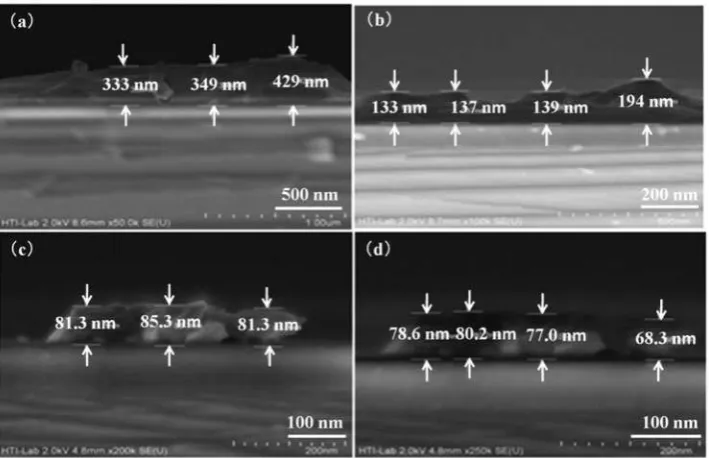
The formation of catalyst thin film on the Si wafer before the heat treatment process with four different spin speeds is shown in Fig. 1a–d. A variation in the thin film thickness obtained showed that the deposited thin films were developed in continuous pattern. A dramatic decrease in thickness at 6500 and 7000 rev min21, the
thickness reduced from 343 to 137 nm, which is mainly due to the increasing speed (Fig. 2). When the spin speed reached a stable thickness, the thickness did not dramatically decrease as shown in spin speed of 6500 to 7000 rev min21. The decreasing of thickness reduced
,20 to 30 nm when the spin speed is increased to 7500
and 8000 rev min21. The pattern of the result showed
that, by increasing the spin speed, the thickness of the catalyst thin film becomes thinner.
The decreasing thickness of thin film by increasing the spin speed of spin coating was due to the thinning process. It is suggested due to the centrifugal force, which developed to reduce thickness of the thin film. By increasing the spin speed, more centrifugal force was created, causing the centrifugal force to create a force that acts downward to push the thin film and make it thinner as shown in Fig. 3. It is also supported by a simple mathematical model of spin coating process
Table 1 Materials for Fe catalyst thin film preparation
Materials (and its ratio)
Precursor Iron nitrate nonahydrate (FeN3O9.9H2O)
Colloidal solution Ethanol/PEG-400 (1/1) (v/v)
Substrate cleaning solution (piranha solution) H2SO4/H2O2(1/1) (v/v)
1 Field emission SEM images of Fe catalyst thin films at spin speed ofa 6500,b 7000,c7500 andd 8000 rev min21 and
preheated at 250uC; note that different scales were used in order to get clearer images
Table 2 Design of experiment for spin coating and heat treatment parameter (spin duration and volume of solution fixed to 30 s and 50mm respectively)
Spin speed/rev min21
Heat treatment
proposed by Emslie’s group to predict the film thickness as a function of a number of physical parameters as follows, wherehois the initial film thickness,vthe spin speed andgthe viscosity16
h~ ho 1z4v
2h2 ot
3g
1= 2
(1)
Controlling the thickness of the catalyst thin film is very important because it will affect the diameter of the catalyst nanoparticle. Thus, if the thickness of the thin film is thick, the diameter of the catalyst nanoparticles will be larger. However, if one can control the thin film thickness, smaller nanoparticle formation is possible,
which will lead to the efficient growth of SWCNT rather than multiwalled CNT.17
Influence of heat treatment to particle formation
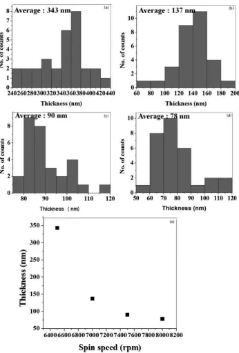
Figure 4 depicts the formation of Fe nanoparticle on the Si wafer after the post-heat treatment process with four different temperatures. In the case of 350 and 400uC heat treatment temperatures, the particle agglomerates and becomes one large cluster (Fig. 4a and b). As the temperature increased to 450 and 500uC, Fe particles start to form without agglomerate and are well dispersed on the substrate. In addition, from the average diameter analysis using histogram in Fig. 5, it was found that with the increasing heat treatment temperature, the diameter of Fe catalyst particles gradually decreased. The2 Histograms of Fe catalyst thin films thickness ofn530 with spin speed of a6500,b 7000,c7500 and d8000 rev min21
formation of Fe catalyst nanoparticles is strongly influenced by post-heat treatment temperature.
Schematic illustration of particle formation at differ-ent temperatures is shown in Fig. 6. It is conceivable that at lower temperatures, the particles tend to agglomerate and become large cluster. When the temperature is equal or.450uC, the particles bonding started to break and cause the particles to fall apart, and this is known as bond breaking. The chemical bond breaking was due to the absorbed energy by the cluster. When the supplied energy was increased, the atoms inside the particles started to repel from each other. Once the iron particles have enough energy to be independent, then the chemical bonding between each particle started to break.
As evidenced in SEM image in Fig. 5, when the temperature increased to 450uC, the particles are no longer combining as a cluster, but the particles are still in irregular (not spherical) shape. When the temperature increased to 500uC, the particles have gained enough energy to form round shape of particles. The round shape of particles indicated that the particles were in a stable state condition. This condition was also related to the good interaction between the catalyst particles and silicon substrate. Thus, this phenomenon caused well distribution of particles on
the substrate. The formation of Fe catalyst nanoparticles is very vital for the CNT growth because it will act as the cap for the CNT to growth.7
Suggested mechanism of thin film and particle
formation
Catalyst thin film and particle formation is correlated to each other. The thickness of the deposited thin film will influence the size of catalyst particles formation. Larger size of catalyst particles will be formed from the thick thin film. In order to produce good thin film and catalyst particles, the spin speed of spin coater and the heat treatment temperature of heat treatment needs to be controlled. The size of particles is very important for the CNT growth.5By controlling spin speed of spin coating and post-heat treatment temperature, a production of uniform thin film, consequently fine size of catalyst nanoparticles, is possible.
The suggested mechanism of thin film and particle formation in Fig. 7 shows that the relationship of spin coating and heat treatment process is very important in producing thin film, as well as to promote the formation of particles. As the process is moving from spin coating to heat treatment, parameter-like spin speed and heat treatment temperatures are very crucial in achieving good particle formation to grow CNTs.
Conclusions
From the work, it was found that.
1. Formation of Fe thin films is possible by spin coated Fe based solution with a concentration of 40 mmol L21. By controlling the spin speed of spin
coating, the optimum thickness of Fe thin films can be achieved. Fe thin film with an average thickness of 78 nm was achieved at spin speed of 8000 rev min21.
3 Schematic mechanism of thinning process
4 Field emission SEM images of Fe catalyst nanoparticles at temperatures of a 350, b 400, c 450 and d 500uC spin coated at 8000 rev min21; samples are in different scales
2. By increasing the post-heat treatment temperature from 350 to 500uC, the cluster formed at lowest temperature started to break down into small particles at the highest temperature. Fe nanoparticles were formed at post-heat treatment temperature of 500uC. Average particle size at 500uC was 9?67 nm.
3. It is suggested that, by controlling spin speed of spin coating and the post-heat treatment temperature, a thin film with a fine size of particles can be achieved. In addition, the
size of catalyst nanoparticles is very critical because it may influence the formation and growth of CNT.
Acknowledgements
The authors gratefully acknowledge the financial sup-port by the Ministry of Higher Education, Malaysia for the Exploratory Research Grant Scheme (research grant no. E00032).
References
1. M. A. Azam, N. S. A. Manaf, E. Talib and M. S. A. Bistamam: ‘Aligned carbon nanotube from catalytic chemical vapour deposi-tion technique for energy storage device: a review’,Ionics, 2013,19, 1455–1476.
2. H. Ago, S. Ohshima, K. Uchida, T. Komatsu and M. Yumura: ‘Carbon nanotube synthesis using colloidal solution of metal nanoparticles’,J. Phys. Condens. Matter, 2002,323, 306–307. 3. H. Sugime, S. Noda, S. Maruyama and Y. Yamaguchi: ‘Multiple
‘optimum’ conditions for Co–Mo catalyzed growth of vertically aligned single-walled carbon nanotube forests’,Carbon, 2009,47, 234–241.
4. K. Teo, C. Singh, M. Chhowalla and W. Milne: ‘Catalytic synthesis of carbon nanotubes and nanofibers’,Encycl. Nanosci. Nanotechnol., 2003,10.
5. G. Zhang, D. Mann, L. Zhang, A. Javey, Y. Li, E. Yenilmez, Q. Wang, J. P. McVittie, Y. Nishi, J. Gibbons and H. Dai: ‘Ultra-high-yield growth of vertical single-walled carbon nanotubes: Hidden roles of hydrogen and oxygen’, Proc. Natl. Acad. Sci. U.S.A.,2005,102, 16141–16145.
6. M. A. Abdeen: ‘Synthesis of carbon nanotubes on silicon substrates using alcohol catalytic chemical vapor deposition’, Mater. Sci. Appl.,2011,2, 922–935.
7. C. M. Seah, S.-P. Chai, S. Ichikawa and A. R. Mohamed: ‘Growth of uniform thin-walled carbon nanotubes with spin-coated Fe catalyst and the correlation between the pre-growth catalyst size and the nanotube diameter’,J. Nanopart. Res., 2013,15, 1371– 1381.
8. M. A. Azam, A. Fujiwara and T. Shimoda: ‘Thermally oxidized aluminum as catalyst-support layer for vertically aligned single-walled carbon nanotube growth using ethanol’,Appl. Surf. Sci., 2011,258, 873–882.
9. M. A. Azam, M. W. A. Rashid, K. Isomura, A. Fujiwara and T. Shimoda: ‘X-ray and morphological characterization of Al-O thin films used for vertically aligned single-walled carbon nanotube growth’,Adv. Mater. Res., 2012,620, 213–218.
10. B. W. Shivaraj, H. N. Narasimha Murthy, M. Krishna and S. C. Sharma: ‘Investigation of influence of spin coating parameters on the morphology of ZnO thin films by Taguchi Method’,Int. J. Thin Film. Sci. Technol., 2013,2, 143–154.
11. C. M. Seah, S.-P. Chai, S. Ichikawa and A. R. Mohamed: ‘Synthesis of single-walled carbon nanotubes over a spin-coated Fe catalyst in an ethanol–PEG colloidal solution’,Carbon, 2012,50, 960–967.
12. B. Bra¨uer, D. R. T. Zahn, T. Ru¨ffer and G. Salvan: ‘Deposition of thin films of a transition metal complex by spin coating’,Chem. Phys. Lett., 2006,432, 226–229.
13. H. R. Barzegar, F. Nitze, T. Sharifi, M. Ramstedt, C. W. Tai, A. Malolepszy, L. Stobinski and T. Wa˚gberg: ‘Simple dip-coating process for the synthesis of small diameter single-walled carbon nanotubes-effect of catalyst composition and catalyst particle size on chirality and diameter’,J. Phys. Chem. C, 2012,116C, 12232–12239. 14. E. Terrado, M. Redrado, E. Mun, W. K. Maser, A. M. Benito and M. T. Mart: ‘Carbon nanotube growth on cobalt-sprayed substrates by thermal CVD,Mater. Sci. Eng. C, 2006,C26, 1185– 1188.
15. A. H. Jayatissa, K. Guo, A. C. Jayasuriya and T. Gupta: ‘Fabrication of nanocrystalline cobalt oxide via sol–gel coating’, Mater. Sci. Eng. B, 2007,B144, 69–72.
16. A. G. Emslie, F. T. Bonner and L. G. Peck: ‘Flow of a viscous on a rotating disk’,J. Appl. Phys., 1958,29, 858–862.
17. C. M. Seah, S.-P. Chai, S. Ichikawa and A. R. Mohamed: ‘Control of iron nanoparticle size by manipulating PEG–ethanol colloidal solutions and spin-coating parameters for the growth of single-walled carbon nanotubes’,Particuology, 2013,11, 394–400.
6 Schematic illustration of particles formation at various temperatures
7 Suggested mechanism of thin film and particles formation