UNIVERSITI TEKNIKAL MALAYSIA MELAKA
INFLUENCE OF SOLUTION PROCESS PARAMETER TO IRON
CATALYST THIN FILM AND PARTICLE FORMATION
This report submitted in accordance with requirement of the Universiti Teknikal Malaysia Melaka (UTeM) for the Bachelor Degree of Manufacturing Engineering
(Engineering Material) (Hons.)
by
ZULHILMI BIN MOHAMED NAWI B051110061
891018145657
i
ABSTRACT
ii
ABSTRAK
iii
DEDICATION
To my beloved family, I have devoted all my effort in order to accomplish this PSM 1 report.
The reason why I devote all my effort in this report is because I want my family to know
especially my beloved mother madam Azizah that I have done my best in order for me to full fill
all bachelor degree program. On top of that, I dedicate this report to my supervisor which has
iv
ACKNOWLEDGEMENT
Syukur Alhamdulillah, our god Allah to still allow the breath flowing in my body and let me completes this PSM 1 report. I would like to thank my supervisor Dr Mohd Asyadi Azam that help me a lot and guide me to complete the first part of the whole program of PSM. Not forgotten, the Master student, Miss Najiha and my entire class mate who help me in giving idea on how to tackle some issue regarding this report. On top of that, to
1
CHAPTER 1
INTRODUCTION
1.1 Background
2 1.1.1 Carbon nanotube (CNT)
The main motivation of this project is the needs to form particle from thin film that will next be used to grow CNTs. CNTs is a material with a shape of tube, which made of carbon that has a diameter in nano scale size (Kumar and Ando, 2010). The capacity of CNT is having an high thermal conductivity with outstanding current carrying capacity and have high flexibility of CNTs promise to resolve problem in the connect area, with the low operative electron and hole mass. The attractiveness band gap and the lack of dangling bonds indicate the needs of a fast, energy efficient and high dielectric suitable device for the future (Kreupl, 2008). Other than that, CNT have a unique nanostructure with remarkable mechanical properties (Medhekar, 2004). The following interest was the promise that the remarkable structure and properties of carbon nanotubes might give rise to some unique applications.
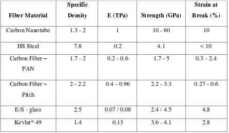
CNT shows a combination of strength, stiffness and firmness as compared to other fiber materials which usually lack one or more of these properties. Thermal and electrical conductivity are also very high, and comparable to other conductive materials.
Table 1.1: Mechanical Properties of Engineering Fiber. (nanocyl 2013)
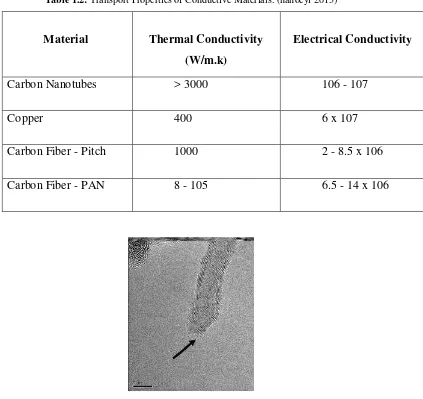
3 Table 1.2: Transport Properties of Conductive Materials. (nanocyl 2013)
Material Thermal Conductivity (W/m.k)
Electrical Conductivity
Carbon Nanotubes > 3000 106 - 107
Copper 400 6 x 10⁷
Carbon Fiber - Pitch 1000 2 - 8.5 x 10⁶
Carbon Fiber - PAN 8 - 105 6.5 - 14 x 106
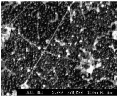
Figure 1.1: CNT growth by CCVD with scale 5nm. (Wang et al, 2007)
4 1.2 Problem statement
The formation of catalyst thin film for CNT usually accomplish by using physical vapor deposition (PVD) due to the proses able to produce a uniform thin film. Even though the process have high capability in producing such uniform thin film, most of manufacturer still looking for other methods to replace an existing proses. This is prior to energy consumed by the process. The PVD process also need to done in a vacuum system. Due to this entire factor, it increased the total operating cost which leads to an expensive cost of product
Spin coating process is the best ways in order to resolve this problem. Even though the proses is promising, the process are still lacking in the control of the uniformity of the thin film and the particle formation size.
The formation of particles on catalyst thin film is very important for CNT growth because the uniformity of the catalyst thin film thickness is very crucial. This is because the surface roughness will affect the size of particles formation. The particle size will be smaller when the uniform thickness is successfully achieved. In order to control the uniformity of the thickness of the catalyst thin film, there are some parameters that needed to be controlled during the spin coating process. The parameters are rotation speed, process duration and spin time. By controlling this parameter, the uniformity of the catalyst thin film on iron catalyst can be controlled.
5 1.3 Objective
i. To synthesis uniform thickness of iron nitrate catalyst thin film by controlling the spin coating parameter.
ii. To study the influence of heat treatment process and the particles formation.
1.4 Scope
This research will be based on several scopes to ensure that the project will not be distracted by other factors.
i. To achieved the first objective, the parameter and scope will cover on: The preparation of solvent based on iron nitrate precursor.
The spin speed of the spin coating machine from 6500 rpm to 8000rpm.
ii. For the second objective, the scope covers are:
The annealing temperature is done on vacuum furnace.
The range of temperature for annealing treatment is from 350ºC to 500ºC
6
CHAPTER 2
LITERATURE REVIEW
2.1 Introduction
7 2.2 Solution process/ Sol-gel process
The sol-gel method was developed in the year of 1960s which principally due to the needs of production way in the nuclear industry. Sol-gel process is defined as construction of an oxide network through polycondensation responses of a molecular precursor in a liquid (Huang et al., 2001).
A sol is actually a dispersion of colloidal particles or polymer in solvent. The particles can be in a form of amorphous or crystalline, while a sol is a particle in a liquid. A sol disperses of the solid particles (> 0.1-1µm) in a liquid where only the Brownian motions dangle the particles (Huang et al., 2001).
A gel is a condition where both liquid and solid are dispersed into one and other, whereby it show a solid network having liquid components. A gel is comprises of a three dimensional continuous network, which surrounds by liquids. In a colloidal gel, the network is constructed from combination of colloidal particles. In the polymer gel, the particles have a polymeric structure sub-structure made by wholes of sub-colloidal particles.
2.2.1 Sol-gel processing method
8 number of developments in originator solutions, coating processes and apparatus have made the sol-gel technique even more widespread. The sol-gel process can be classified into two different routes depending on the nature of the precursor which are the precursor is an aqueous solution of an inorganic salt or a metal organic compound (Niederberger and Nicola 2009).
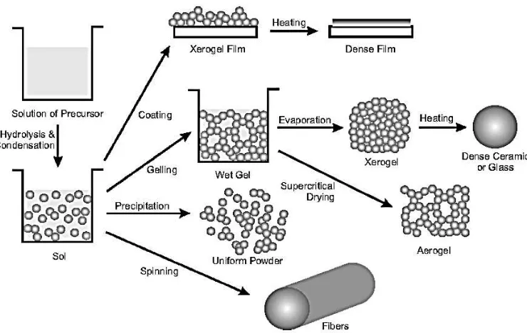
Several methods can be used to make sol-gel coatings with the sol-gel process as mention in Figure 2.1. Spin coating and dip coating are two basic techniques applied to deposit the sol gel coating on the substrate. Spin coating is one sided coating compared to dip coating; it can be done in both sites which is double sided coating. Both techniques are used to manufacture different coating on thin film.
Figure 2.1: Sol-gel processing method. (Niederberger and Nicola 2009)
9 2.2.2 Advantages of sol-gel process
As mentioned before, sol-gel process is a process that offers many advantages compared to other thin film deposition method. One of the main advantage sis it can produce thin bond-coating to provide excellent adhesion between the metallic substrate and the top coat. The list below is the additional advantages that can be offered by sol-gel technique:
i. Provide corrosion protection by its thick coating.
ii. It can easily shape materials into complex geometries in a gel state
iii. It can produce high purity products because the organo-metallic precursor of the desired ceramic oxides can be mixed, dissolved in a specified solvent and the composition can be highly controllable.
iv. It can have low temperature sintering capability, usually 200-600°C.
v. It can provide a simple, economic and effective method to produce high quality coatings.
2.2.3 Disadvantages of sol-gel process
Apart from its advantages, sol-gel processes still have some lacking due to some limitations such as high permeability, low wear resistance, week bonding and hard to control the porosity. In specific, maximum limit of the coating thickness is 0.5µ m when
10 2.3 Spin coating thin film
Spin coating process is at this time the major method used to create uniform thin film of photosensitive organic materials with micrometers and nanometers thickness. The pioneer in the study of spin coating was accomplished with more than fifty years ago by Emil who deliberated the spreading of a thin film axisymmetric of the Newtonian fluids on a proposer rotating substrates with an angular speed (Sahu et al., 2009). In most cases, the polymeric coating material is applied in a solution form, where the solution vaporizes. Paint and pitch coating was the first the being studies using spin coating.
The spin coating process is extensively used in the manufacturing of integrated circuit, optical glass mirror, screen color television and magnetic disk function for storing data. Centrifugal force moving the liquids radiated outward. The surface tension and viscous force cause the thin residual film to be retained on the flat substrate surface. The thickness of the film can be reduced by the combination of both factors which are the evaporation and outward fluid flow.
11 2.3.1 Procedure of spin coating method
Deposition of thin films by spin-coating is a very simple and widely used technique to prepare films of uniform thickness of non-volatile materials initially found in liquid solution dissolved in a volatile solvent. The technique is particularly suitable to obtain thin films of conjugated polymers (Aguilar& Lopez, 2011) from their solutions in organic solvents or in liquids.
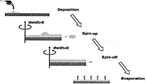
The physics of spin coating can be effectively modeled by dividing the whole process into four stages, which were the deposition stage, spin up stage, spin off stage and the evaporation of liquid. Usually, the first two stages commonly in sequel, but the spin off stage and the evaporation stage commonly overlap. The stage 3 (flow controlled) and stage 4 (evaporation controlled) are two stages that contribute most on the final thickness of thin film (Sahu et al., 2009).
Figure 2.2: Spin coating processing sequence. (Sahu et al., 2009)
2.3.1.1 Deposition
12 stage where it transporting an excess of the liquids onto the substrate surface which it immediately covered or wetted. During this stage, deposition of liquid can be in many ways such as:
i. As a heavy rain that covers the whole disk.
ii. As a smacking at the center and the liquids will covered the entire disk by the commonly defined by the fluid removal aggressiveness from the rotational motion on its water surface. Due to the depth of initial fluid on the water surface, the present of spiral twisted might be found at this stage. This might be the result from the twisting motion caused by motion of inertia that the top of the fluid layer and at the same time, the water below keeps rotating in increasing speed. When, the liquid is thin enough, which it’s completely co-rotating with the substrate, the difference between the thicknesses is gone. Finally, when the substrate reaches its desired speed and the thickness of the thin film is thin enough, the viscous shear drag the rotational acceleration balance.
2.3.1.3Spin off
13 stable condition. The thickness is depending on the viscosity, surface tension, rotation rate and etc., there may be a small drop of coating thickness difference around the edge of the final wafer. If the fluid thickness is initially uniform across the wafer then the fluid thickness profile at any following time will also be uniformed.
2.3.1.4Evaporation
An inert gas flow on top of the surface causing the functional liquids to vaporize that leads to super saturation process. The crystalline of salt catalyst is out uniformly. Due to the short time of evaporation (within few second), the crystal that form is in nanometer sized (Medhekar, 2004).
2.2.3 Advantages and disadvantages of spin coating thin film
There are many advantages offered by the spin coating process whereby the thin film thickness can be change easily by changing the spin speed of the spin coater or change the viscosity of the liquids. As compared with other coating techniques, there are too many parameters that need to be control leading to a more complex process
14 2.4 Catalyst thin film
As we all know, the properties of the catalyst effects on the growth of the nanotubes. The formation of catalyst of catalyst thin film is very important for the CNT growth. There are many techniques used for developing catalyst thin film such as Chemical Vapor Deposition (CVD), Laser Ablation method and Arc-discharge technique in which have a huge lapping in there process because the manufacturing of catalyst cluster on flat surface is not completely controlled. Most of the techniques used including CVD do not give much control to the growth and the properties of the carbon nanotubes. The thickness of the catalyst of the thin film need to be control because the catalyst that deposited on the substrate is going to be used to grow the carbon nanotubes.
2.4.1 Catalyst thin film formation
15 2.4.2 Particle formation on catalyst thin film
The formation of catalyst particles with various size variations is observed in order to understand effect of various types of parameters with the formation of particles. For the purpose of analysis, the distribution of uniform catalyst on the entire surface of substrate, it is helpful to compared between the average thin film thicknesses with the surface roughness. It is likely for the catalyst thin film continuous when the roughness is smaller than the thickness.
On the other hand, if the catalyst average value thickness is lower than the roughness value, separate particles formation is possible. Most of the cases show that small elongated catalyst particles can be detected at the end of tip of tubes. This indicates that the growth mechanism is tip grow (Moshkalyov et al., 2004). The density of the nanotubes be determined the treatment on the catalyst before the synthesis and on the delay between the film deposition and the process. The growth process and the nanotube nucleation depend strongly on the catalyst film thickness and on the conditions of the treatment on surface before growth. A good result is a long straight carbon nanotube with diameter of 10 nm smal or less was obtained at high growth temperatures.
Figure 2.3: SEM image of nanotubes grown by thermal CVD, H2/CH4 = 400/100 sccm, 900 8C, 20 min, 1
16 2.4.3 Catalyst thin film through solution process
As discussed before, the simplicity of the spin coating process for depositing the catalyst on the flat surface such as silica (SiO2) and alumina single crystal (Al2O3) Spin coating process is employed in order to deposited a fine layer functional solution on the flat surface. The usage flat surface support which consists of SiO2 and AL2O3 giive a huge benefits with respect of sensitive spectroscopic surface methods (Medhekar, 2004). One of the benefits is the catalyst is ready and available for analysis. Flat surface support also enables the use of methods such as tunneling microscopy (STM) and atomic force microscopy (AFM). The transportation of heat transfer and mass to the surface of the catalyst from the mixture of reaction are commonly gone the result is fairly easy to interprets
The used of catalyst for CNTs growth which basically been supported on the alumina or silica which consist of porous catalyst support. In this system, the catalyst distribution cluster and the characteristic made it difficult by the incapability to control the cluster nature that contributes to the formation on CNTs. Other than that, the control of catalyst size is very difficult because of few factors such as speed and the concentration of the solution.
2.4.4 Parameter that influence the catalyst thin film and particles formation
17 2.4.4.1 Effect on concentration of solution
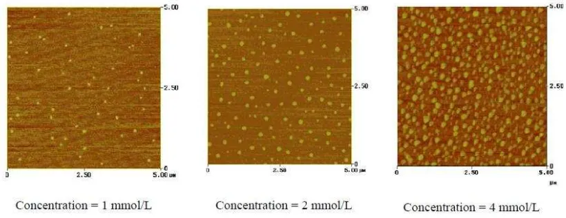
Concentration of the solution is one of the most important parameter in the formation of the catalyst thin film. This is mainly because the thickness of the catalyst thin film can be controlled by adjusting the concentration of the solution. The density of CNT thin films was controlled by the concentration of catalyst in the solution (Sangwan et al, 2010). Other than that, the higher number of concentration of salt, more amount of solid solution present to crystalize. The formation of more than one cluster happened when the material is concentrated. It can be said that, the particle density and also the particle size increase with increasing concentration of crystal salt as mention in Figure 2.4.
Figure 2.4: AFM images on different concentration prove that high concentration will increase the
thickness of the catalyst thin film. (Medhekar, 2004)
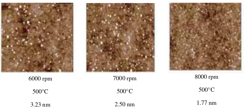
2.4.4.2 Effect on speed of spin coating
18 substrate surface due to the capillary force that influence leads to the reduce amount of salt solution (Medhekar, 2004). The quantity of deposited solid on the surface after the evaporation of the liquids solution is less and is revealed in the shape of fine fize of particle on the surface as shown in Figure 2.5.
Figure 2.5: AFM images show that the particle size and density will decrease at high speed of spin coated
thin film. (Wei et al., 2009)
2.4.4.3 Effect of temperature on catalyst particle
The stability and the uniformity of the cluster play an important role in formation of CNTs and also their properties. Cluster combines at high temperature of oxidation or reduction and the reaction of the salt are treated to gain the catalyst metal (Medhekar, 2004). With the suitable temperature, the large agglomeration of iron salt can be prevented. There are two ways to prevent the cluster to agglomerates which are reduction and oxidation.