HEXAPOD MOTOR CONTROLLER USING FPGA
MOHAMAD SOLEHIN BIN MOHAMED SUNAR
This Report Is Submitted In Partial Fulfillment of Requirements For The Bachelor Degree in Electronic Engineering (Computer Engineering)
Fakulti Kejuruteraan Elektronik dan Kejuruteraan Komputer Universiti Teknikal Malaysia Melaka
v
vi
ACKNOWLEDGEMENT
vii
ABSTRACT
viii
ABSTRAK
ix
TABLE OF CONTENTS
TITLE PAGE
PROJECT TITLE i
REPORT AUTHORIZATION FORM ii
DECLARATION iii SUPERVISOR’S DECLARATION iv DEDICATION v ACKNOWLEDGEMENT ... vi
ABSTRACT ... vii
ABSTRAK ... viii
TABLE OF CONTENTS ... ix
LIST OF TABLES ... xiii
TABLE OF FIGURES ...xv
ABBREVIATIONS ... xix
CHAPTER I ... 1
1.1Project Overview ... 1
1.2Problem Statement ... 2
1.3Objectives ... 3
1.4Scope Of The Project ... 3
CHAPTER II ... 4
2.1Introduction ... 4
2.2Hexapod Robot ... 4
2.3Gait Analysis ... 5
x
2.3.2 Crab ... 6
2.3.3 Pentapod ... 6
2.3.4 Single Leg Controller... 7
2.3.5 Degrees Of Freedom ... 7
2.4Papilio One ... 8
2.4.1 Power ... 8
2.4.2 USB ... 8
2.4.3 SPI Flash ... 9
2.4.4 Wings ... 9
2.4.5 Dimensions ... 9
2.4.6 Spartan 6 FPGA Chip ...10
2.5Servo Motor ...11
2.6PWM Signal ...12
2.6.1 Forward (Clockwise, CW) ...13
2.6.2 Normal Position (N) ...13
2.6.3 Reverse (Counter Clockwise, CCW) ...13
CHAPTER III ...14
3.1Introduction ...14
3.2 Project Activities ...15
3.3Hexapod Movement Algorithm ...16
3.4Pentapod Gait ...16
3.5Algorithm (Pentapod Gait)...17
3.5.1 State 1...17
3.5.2 State 2...18
3.5.3 State 3...18
3.5.4 State 4...19
xi
3.5.6 State 6...20
3.5.7 State 7...20
3.5.8 State 8...21
3.5.9 State 9...21
3.5.10 State 10 ...22
3.5.11 State 11 ...22
3.5.12 State 12 ...23
3.5.13 State 13 ...23
3.5.14 State 14 ...24
3.5.15 State 15 ...24
3.5.16 State 16 ...25
3.5.17 State 17 ...25
3.5.18 State 18 ...26
3.5.19 State 19 ...26
3.5.20 State 20 ...27
CHAPTER IV ...28
4.1RTL (Register Transfer Level) ...28
4.2Simulation ...31
4.3Simulation Results ...33
4.3.1 State 1...33
4.3.2 State 2...34
4.3.3 State 3...35
4.3.4 State 4...36
4.3.5 State 5...37
4.3.6 State 6...38
4.3.7 State 7...39
xii
4.3.9 State 9...41
4.3.10 State 10 ...42
4.3.11 State 11 ...43
4.3.12 State 12 ...44
4.3.13 State 13 ...45
4.3.14 State 14 ...46
4.3.15 State 15 ...47
4.3.16 State 16 ...48
4.3.17 State 17 ...49
4.3.18 State 18 ...50
4.3.19 State 19 ...51
4.3.20 State 20 ...52
4.4Discussion ...53
CHAPTER V ...56
5.1Conclusion...56
5.2Recommendation ...57
REFERENCES ...58
APPENDIX ...59
6.1Appendix A ...59
6.2Appendix B ...60
xiii
LIST OF TABLES
NO. TITLE PAGES
Table 1 Type of directional movement and the value of pulse for each
movement. ...17
Table 2 Movement at State 1 ...17
Table 3 Movement at State 2 ...18
Table 4 Movement at State 3 ...18
Table 5 Movement at State 4 ...19
Table 6 Movement at State 5 ...19
Table 7 Movement at State 6 ...20
Table 8 Movement at State 7 ...20
Table 9 Movement at State 8 ...21
Table 10 Movement at State 9 ...21
Table 11 Movement at State 10 ...22
Table 12 Movement at State 11 ...22
Table 13 Movement at State 12 ...23
Table 14 Movement at State 13 ...23
Table 15 Movement at State 14 ...24
Table 16 Movement at State 15 ...24
Table 17 Movement at State 16 ...25
Table 18 Movement at State 17 ...25
Table 19 Movement at State 18 ...26
Table 20 Movement at State 19 ...26
Table 21 Movement at State 20 ...27
xiv
Table 23 Top.v Verilog code ...62
Table 24 GaitControl.v Verilog code ...63
Table 25 Top.ucf Verilog code ...73
xv
TABLE OF FIGURES
NO. TITLE PAGES
Figure.1 The robot consists of 6 legs. Each leg has 3 servo motors and it will make a total up of a servo motor is 18. This robot is used in hardware section which is it will be working when the Verilog code are complete. Every servo motor will connect to Papilio board where the coding is burned into the Spartan-6 FPGA chip ... 5 Figure 2 The six legs are treated in two groups of three. Either group of three is
a tripod formed by the front and rear legs on one side, and the middle leg of the opposite side. The three component legs of each tripod are moved as a unit. As tripod is lifted, the other tripod pushes forward. . 6 Figure 3 Servomotor closest to the robot body known as the servo motor 3.
Followed by servo motor 2 and the outside is a servo motor 1. Servo motors 1 and 2 have the same mode of operation that moves up and down while the servo motor 3 only move left and right. ... 7 Figure 4 The Papilio One is a powerful and expandable development board
perfect for the design and prototyping of your unique ideas. We can customize the capabilities of the Papilio with snap-on modular expansions called Wings (similar to Arduino shields) which provide added functionality to the board, and simultaneously expand the creative possibilities ... 8 Figure 5 Spartan 6 FPGA Chip is used as the brain of the controller, which
xvi
Figure 6 Servomotor allows for a precise control of angular position, velocity and acceleration. Servomotor commonly are small in size, but can
give a big punch and are very energy-efficient. ...12
Figure 7 Forward Pulse Period ...13
Figure 8 Maintain Pulse Period...13
Figure 9 Reverse Pulse Period ...13
Figure 10 The project schedule or Flow chart will be helpful in tracking the current progress of the project. Planning was needed to identify the scheduled task that needs to be carried out to make sure the project run smoothly ...15
Figure 11 Block Diagram (Hexapod Robot) Block diagram shows that each leg will connected to three servo motors. ...16
Figure 12 Register transfer level schematic (TOP) ...29
Figure 13 Gait control schematic ...30
Figure 14 Waveforms generate in Isim ...31
Figure 15 Declaration for N position (servo_pwmC1) ...31
Figure 16 Waveforms generate in Isim ...31
Figure 17 Declaration for CW movement (servo_pwmA2) ...32
Figure 18 Waveforms generate in Isim ...32
Figure 19 Declaration for CCW movement. (servo_pwmA1) ...32
Figure 20 State 1 can be considered as the original position of the robot. Algorithm set for each motor to move (a). This allows the robot to stand up and be in a state of (b). The algorithm will produce a simulation as in (c). ...33
Figure 21 Servomotor B2 and B3 will move according to the algorithm in State 2 (a). Movement of the leg lift up is shown in figure (b). Simulation of the entire State 2 is shown in (c)...34
xvii
Figure 23 In State 4, there are changes in servo motor algorithm for B2 and B3 (a) and will make leg moves down (b). Simulation for State 4 are shown in (c). ...36 Figure 24 Servomotor C2 and C3 will move according to the algorithm in State
5 (a). Movement of the leg lift up is shown in figure (b). Simulation of the entire State 5 is shown in (c)...37 Figure 25 Servomotor (C1) will move according to the algorithm in State 6 (a).
The movement of the leg to the left as shown in Figure (b). Simulation of the entire State 6 is shown in (c)...38 Figure 26 In State 7, there are changes in servo motor algorithm for C2 and C3
(a) and it will make leg moves down (b). Simulation for State 7 are shown in (c). ...39 Figure 27 Servomotor D2 and D3 will move according to the algorithm in State
8 (a). Movement of the leg lift up is shown in figure (b). Simulation of the entire State 8 is shown in (c)...40 Figure 28 Servomotor (D1) will move according to the algorithm in State 9 (a).
The movement of the leg to the left as shown in Figure (b). Simulation of the entire State 9 is shown in (c)...41 Figure 29 In State 10, there are changes in servo motor algorithm for D2 and D3
(a) and it will make leg moves down (b). Simulation for State 10 are shown in (c). ...42 Figure 30 Servomotor A2 and A3 will move according to the algorithm in State
11 (a). Movement of the leg lift up is shown in figure (b). Simulation of the entire State 11 is shown in (c). ...43 Figure 31 Servomotor (A1) will move according to the algorithm in State 12 (a).
The movement of the leg to the right as shown in Figure (b). Simulation of the entire State 12 is shown in (c). ...44 Figure 32 In State 13, there are changes in servo motor algorithm for A2 and A3
xviii
Figure 33 Servomotor F2 and F3 will move according to the algorithm in State 14 (a). Movement of the leg lift up is shown in figure (b). Simulation of the entire State 14 is shown in (c). ...46 Figure 34 Servomotor (F1) will move according to the algorithm in State 15 (a).
The movement of the leg to the right as shown in Figure (b). Simulation of the entire State 15 is shown in (c). ...47 Figure 35 In State 16, there are changes in servo motor algorithm for F2 and F3
(a) and it will make leg moves down (b). Simulation for State 16 are shown in (c). ...48 Figure 36 Servomotor E2 and E3 will move according to the algorithm in State
17 (a). Movement of the leg lift up is shown in figure (b). Simulation of the entire State 17 is shown in (c). ...49 Figure 37 Servomotor (E1) will move according to the algorithm in State 18 (a).
The movement of the leg to the right as shown in Figure (b). Simulation of the entire State 18 is shown in (c). ...50 Figure 38 In State 19, there are changes in servo motor algorithm for E2 and E3
(a) and it will make leg moves down (b). Simulation for State 19 are shown in (c). ...51 Figure 39 State 20 can be considered as the original position of the robot.
xix
ABBREVIATIONS
FPGA Field Programmable Gate Array
IC Integrated Circuit
I/O Input Output
HDL Hardware Description Language PWM Pulse Width Modulation
ISE Integrated Software Environment USB Universal Serial Bus
DC Direct Current
EEPROM Electrical Erasable Programmable Read Only Memory
RAM Random Access Memory
CW Clockwise
CCW Counter-Clockwise
PSM Projek Sarjana Muda
1
CHAPTER I
INTRODUCTION
1.1 Project Overview
A microcontroller-based system has been a popular choice in designing a robotic controller. This is due to the simple programming method, numerous supports and hardware availability of various types of motors and design boards. The complexity of the motor controller design is also varied based on the capability of the chosen microcontroller. The low-end microcontroller such as the 8-bit microcontroller would provide the basic requirement to control a servo motor while other higher-rated microcontrollers would offer integhigher-rated peripherals such Pulse Width Modulation generation and other related features that ultimately increase the performance of the controller.
2
instantiate any hardware modules of the circuit design by programming the reconfigurable fabric using Hardware Description Language. Therefore, the designer has the complete control on the hardware synthesis of the design and directly determined the required I/O ports for the particular controller of a robotic system. As the term reconfigurable implies, the existing circuit design could be reconfigured and modified when required. The I/O configurations of the controller could be expanded and reduced on-the-fly without the need to physically replace the controller chip. The flexibility feature in the reconfigurable hardware such as Field Programmable Gate Array would also create a single chip solution for embedded system design where all the hardware modules could be instantiated in one FPGA chip. Therefore, the circuit would be easy to maintain with less board space requirement. This project focused on the design and implementation of a servo motor controller in an FPGA platform. The controller then is interfaced with 18 servomotors which are equipped with a Hexapod robot. PWM pulses are generated for each of the servomotor controller in order to determine the exact position of the servos in relation to the robot’s movement. The controller design is programmed in Verilog, synthesized, translated, mapped and place-and-routed using Xilinx’s Integrated Software Environment (ISE) Design Suite.
All results are simulated and verified using an HDL simulator called ISim simulator and the bit file generated by these processes is programmed on the Spartan-6 FPGA chip. Subsequently, the Hexapod’s movement is tested on a flat surface with the aim to validate the controller execution on the hardware platform.
1.2 Problem Statement
3
The sequential nature of program execution in microcontroller would significantly affect the synchronization of the Hexapod movement. A parallel execution of the motor would ensure more precise movement of the Hexapod robot.
1.3 Objectives
Established Hexapod robot movement mechanism. Design Hexapod controller in FPGA environment
1.4 Scope Of The Project
Each leg has 3 servo motors that act as actuators for the movement. The gait controller is designed to synchronize the position of servomotor in relation to its current movement.
4
CHAPTER II
LITERATURE REVIEW
2.1 Introduction
In this chapter, the Hexapod robot, the leg coordination FPGA based controller, degree of freedom and the servomechanism theory will be discussed. The background study or literature review comes from various resources such as senior’s past project theses, books, and journals. But in some cases, resources like online articles, video and images have also contributed to the better understanding related to the theory of this project.
2.2 Hexapod Robot
5
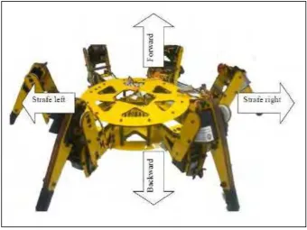
Figure.1 The robot consists of 6 legs. Each leg has 3 servo motors and it will make a
total up of a servo motor is 18. This robot is used in hardware section which is it will be working when the Verilog code are complete. Every servo motor will connect to Papilio board where the coding is burned into the Spartan-6 FPGA chip
2.3 Gait Analysis
Gait analysis refers to the mechanism responsible for controlling leg step transitions (stance and swing) to assure that the Hexapod robot will not tumble. Most approaches try to replicate known insect gaits. However, other approaches have been used to find stable gaits. For instance, by running genetic algorithms or optimizing energy cost function. Basically the movement of the Hexapod is liked human prone and try to move forward or backward.
There is an example of Hexapod locomotion which is: Alternating tripod: 3 legs on the ground at a time. Crab.