HEXAPOD ROBOT MOTOR CONTROLLER USING FPGA
FIKRI NAIM BIN MOHD ROSLI
This report is submitted in partial fulfillment of the requirements for the award of Bachelor of Electronic Engineering (Computer Engineering) With Honors
Faculty of Electronic and Computer Engineering
University Technical Malaysia Melaka
I
For my lovely mum and dad, thanks for sacrifice towards my success.
For my supervisor, Pn. Nur Alisa Bt. Ali, thanks for all your supports
II
ACKNOWLEDGEMENT
III
ABSTRACT
IV
ABSTRAK
V
CONTENTS
CHAPTER DESCRIPTION PAGES
PROJECT TITLE i
DECLARATION ii
DEDICATION v
ACKNOWLEDGEMENT vi
ABSTRACT vii
CONTENTS ix
LIST OF TABLES xiii
LIST OF FIGURES xiv
LIST OF ABBREVIATIONS xvii
LIST OF APPENDIX xviii
I INTRODUCTION 1
1.1 OVERVIEW 1
VI
1.3 PROBLEM STATEMENT 2
1.4 SCOPE 2
1.5 BRIEF EXPLAINATION OF METHODOLOGY 3
1.6 REPORT STRUCTURE 5
II LITERATURE REVIEW 6
2.1 INTRODUCTION 6
2.2 HEXAPOD ROBOT 7
2.2.1 Leg Coordination 7
2.2.2 Single Leg Controller 8
2.2.3 Degrees of freedom 9
2.3 SERVO MOTOR 9
2.3.1 Servo Motor Operation 10
2.3.2 Servo Wiring 11
2.3.3 Servo Voltage 11
2.3.4 Servo Current 12
2.3.5 Servo Velocity 12
2.3.6 Servo Selection 12
VII
2.4 HEXPOD ROBOT MOTOR CONTROLLER 14
2.5 PWM SIGNAL 16
III METHODOLOGY 18
3.1 INTRODUCTION 18
3.2 FLOWCHART OF PROJECT METHODOLOGY 19
3.2.1 Literature Review 20
3.2.2 Hexapod Movement Algorithm 21
3.2.3 Verilog code 26
3.2.4 Thesis writing 27
3.3 PRELIMINARY RESULT 28
IV RESULTS AND DISCUSSION 30
4.1 PRELIMINARY RESULT 30
4.2 EXPECTED RESULT 31
4.3 PROGRAMMING THE LEG ALGORITHM 31
4.4 SIMULATION RESULTS 34
VIII
4.4.2 Synthesize Our Design 41
4.4.3 User Constraints 41
4.4.4 Implement Design 42
4.4.5 Generate Program File 43
4.5 HARDWARE TESTING AND PROGRAM CODE 44
4.8 DISCUSSION
V CONCLUSION AND RECOMMENDATION 48
5.1 CONCLUSION 48
5.2 RECOMMENDATIONS 49
REFERENCES 50
IX
LIST OF TABLES
NO TITLE PAGES
1 Table 1: Movement for time T1 23
2 Table 2: Movement for time T2 23
3 Table 3: Movement for time T3 23
4 Table 1: Movement for time T1 24
5 Table 2: Movement for time T2 24
6 Table 3: Movement for time T3 24
X
LIST OF FIGURES
NO TITLE PAGES
1 Figure 1: Basic block diagram of project 3
2 Figure 2: Flow-chart of project methodology 4
3 Figure 3: Actual image of the project Hexapod robot 7
4 Figure 4: Example of Hexapod robot leg 8
5 Figure 5: Servo motor from HiTEC HS-55 10
6 Figure 6: Diagram of pulse widths sent to control servo motor
position
11
7 Figure 7: Closed-loop velocity servo 13
8 Figure 8: Measuring open-loop characteristic 14
9 Figure 9: LP-2900 Development kit 14
10 Figure 10: Basic Spartan-II Family FPGA block diagram 15
XI turning degree
12 Figure 12: Project methodology flowchart 19
13 Figure 13: Block diagram of the Hexapod robot 21
14 Figure 14: Top angle of the Hexapod robot with positions of
all servo motor
22
15 Figure 15: Example of movement of the servo motor 25
16 Figure 16: Example of new project wizard in Xilinx ISE 26
17 Figure 17: Example of Verilog source program 26
18 Figure 18: Example of PWM module in Xilinx ISE 27
19 Figure 19: Verilog programming for generating a PWM 28
20 Figure 20: Code to do a continuous pulse count 28
21 Figure 21: Comparing pulse count to generate pulses 29
22 Figure 22: Example of complete Verilog programming of RC
Servo PWM signal generation
29
23 Figure 23: Parameter assign as follows 32
24 Figure 24: PWM out pin assignment 33
25 Figure 25: PWM signal generation by overflowing the
accumulator
33
26 Figure 26: Declaration for full rotational for the servo 34
27 Figure 27: 180 degree waveform generate in ModelSim 34
28 Figure 28: Declaration for neutral position 35
[image:15.612.138.531.76.717.2]XII
30 Figure 30: Declaration for -180 position 35
31 Figure 31: Waveform for -180 position 35
32 Figure 32: Full waveform for simulation of the PWM output
signal.
36
33 Figure 33: Flowchart for the whole program 37
34 Figure 34: Register transfer level schematic 38
35 Figure 35: Inside the RTL schematic 39
36 Figure 36: View of RTL technology 40
37 Figure 37: Pin assignment for the project 41
38 Figure 38: Successful design flow 43
39 Figure 39: Program into FPGA chip package 43
40 Figure 40: Actually board with input/output indicator 44
41 Figure 41: SW1 is "0" and SW2 "1" meaning switch 1 is activate
44
42 Figure 42: Waveform when switch 1 (01) is pressed. 45
43 Figure 43: Declaration for testbench taken from Verilog
module
46
44 Figure 44: Initializing input to do a testbench for our module. 46
45 Figure 45: Hexapod robot movement direction 52
[image:16.612.137.535.80.683.2]XIII
LIST OF ABBREVIATIONS
DOF - Degree of Freedom
DC - Direct Current
PWM - Pulse Width Modulation
CCW - Counter Clock Wise
CW - Clock Wise
FPGA - Field Programmable Gate Array
HDL - Hardware Description Language
LED - Light Emitting Diode
XIV
LIST OF APPENDIX
NO TITLE PAGES
A Hexapod movement 52
B Program algorithm 55
1
CHAPTER 1
INTRODUCTION
1.1 Overview
2 Each leg is actuated by three (3) servos which makes 18 servos in total. Hexapod means that the robot will be have 6 legs (Hex). An array of algorithm will be program to make the Hexapod move.
1.2 Objective
Objective of the project are to design algorithm of movement, implement and the design of FPGA based servo motor control for the movement of Hexapod.
1.3 Problem Statement
A robot walks on six legs can be describe as Hexapod robot. Each leg consists of 3 servos which make 18 servos in total. Most of servo control are using PIC based controller. The use of PIC is no longer relevant as there are too many servos to control and to make the hexapod movement more precisely. Therefore, we need to control and achieve multiple servo control synchronization. Using FPGA base controller, we can get a precise movement of control for all servo motor. Others micro-controller like PIC have limited number of servo motor control. Therefore need more than one IC need to be utilized all the servo control for the whole operation. Furthermore, micro-controller like PIC needs larger board size and magnifying the use of discreet IC.
1.4 Project Scope
3
1.5 Brief Explanation of Methodology
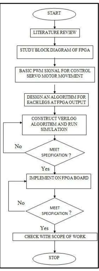
The methodology of this project is made to determine the objective of the project and ensure it will not derail from project‟s scope. Beginning of the project, literature review and background study is made. This is to ensure what, why and how the FPGA based system is different from conventional PIC microcontroller system. Furthermore, this will lead to problem solving method for problem statement that occurs for PIC based Hexapod robot motor controller.
[image:21.612.150.484.404.596.2]After that, the FPGA architecture is study and familiarize. Study on block diagram of the FPGA and the LP-2900 experiment kit which hold the FPGA chip and input/output module on it are made and documented. Basically the controller for this project is place on LP-2900 Spartan II board. On that board have input/output module. The expected use of input are the switches where it control the movement of the Hexapod, while the output will be connected to the eighteen servos motor at each six-leg of the Hexapod. Then, basic PWM signal for control motor movement will be design and developed.
Figure 1: Basic block diagram of project
Next step for project methodology is the most crucial for Hexapod development. The algorithm for each leg to move is carefully design and constructed. Movements were insect-inspired where three crucial aspects are look into. Stability, speed and synchronization of all servos motor are coming into place. This is to ensure the
Switch
•On/Off Hexapod
•Movement
LP-2900 FPGA Experiment Kit
•Input
•Output pin
Hexapod
•Six leg
4 fluidity of the Hexapod movement to move at all terrain and all direction. The servomechanisms that make the Hexapod move are actually generated by the FPGA and this make the FPGA is ideal for Hexapod motor controller.
Figure 2: Flow-chart of project methodology
5 implementation on the FPGA board itself. If the implementation is succeeded, the end result must be check to see whether it is still within the scope of the project and if it does the project can be classify as successfully delivered.
1.6 Report Structure
This report consists of three chapters which are Introduction, Literature Review, and Methodology.
In Chapter 1 is Introduction, discussed about project background, project objectives, problem statement, scope of work, short brief of project methodology and overview the remaining chapters.
In Chapter 2 is Literature Review, reviews some references from previous project, journals, articles, books and datasheet. All the materials was useful to success this project.
6
CHAPTER 2
LITERATURE REVIEW
2.1 Introduction
In this chapter, about the Hexapod robot, the leg coordination FPGA based controller, degree of freedom and the servomechanism theory is discussed. The background study or literature review come from various resources such as:
1. Senior‟s past project thesis
2. Books
3. Journals