0
STUDY AND DEVELOPMENT OF THE DRAG REDUCTION SYSTEM FOR
GO-KART
JULIANOUS KETIHUS
A report in partial fulfilment of the requirements for the degree of Bachelor of
Mechatronics Engineering
Faculty of Electrical Engineering
UNIVERSITI TEKNIKAL MALAYSIA MELAKA
i
“I hereby declare that I have read through this report entitle “Study and Development of The
Drag Reduction System for Go-kart” and found that it has comply the partial fulfilment for awarding the degree of Bachelor of Mechatronics Engineering”
Signature : ...
Supervisor‟s Name : MOHD. ZAMZURI BIN AB. RASHID
ii
STUDY AND DEVELOPMENT OF THE DRAG REDUCTION SYSTEM FOR
GO-KART
JULIANOUS KETIHUS
A report in partial fulfilment of the requirements for the degree of Bachelor of
Mechatronics Engineering
Faculty of Electrical Engineering
UNIVERSITI TEKNIKAL MALAYSIA MELAKA
iii
I declare that this report entitle “Study and development of Drag Reduction System for Go
-kart” is the result of my own research except as cited in the references. The report has not
been accepted for any degree and is not concurrently submitted in candidature of any other
degree.
Signature : ……….
Name : JULIANOUS KETIHUS
iv
v
ACKNOWLEDGEMENT
First of all, I would like to thanks to Almighty God, who has blessed and guided me
for completion of this report as a partial fulfilment for awarding the degree of Bachelor of
Mechatronics Engineering at Universiti Teknikal Malaysia Melaka. A special gratitude and
sincerely thanks to my project supervisor, Encik Mohd Zamzuri bin Abdul Rashid, for
encouragements, guidance critics and correction for this report from the beginning until the
end of this report writing.
In this special moment, I would like to express my deepest thanks to my beloved
parents, Ketihus bin John and Iren binti Angkarul for their love encouragement and supports
both financially and mentally that made me to finishing this report as well as my study.
Last but not least, sincere thanks to all my friends and others who have provided
assistance and contributing their ideas in completing this report. Without their support and
vi
ABSTRACT
Aerodynamic is an important element that needs to be considered in designation of a race car
to achieve the top speed instead of depending only on the engine horsepower. In development
of race car, engineer’s goal is to provide enough downforce, and minimum aerodynamic drag.
The innovative of aerodynamic design affects the speed of a race car, means the more
aerodynamic of the car, the faster the speed of the vehicle and vice versa. However, there are
two enemies or constrains that may affect speed in race car aerodynamics which is excess in
drag force and lack of downforce. The drag is the resultant force in the direction of the
upstream velocity; it opposes the forward motion of the vehicle. Excess in drag (wind
resistance) reducing the effectiveness of the time and requires more horsepower for the engine
to achieve top speed. Lack of downforce can reduce the traction and road grip. Therefore, this
paper addresses the study and development of Drag Reduction System (DRS) for go-kart, a
current technology in aerodynamics world. DRS are an adjustable rear wings used in Formula
One cars to facilitate overtaking by reducing the drag and at the same time reducing
downforce. In order to prove this hypothesis, DRS need to be developed in this project. Then
its performance is tested in simulation and real world test (static test). In the same time, front
and rear wing also required to be fabricated. Development of wings and DRS begins with
conducting a literature study on previous research by several experts and follow by designing
wings model. Process continues with fabrication and development. The final product are
tested in real world environment and simulated by using Solidworks Flow Simulation. The
purpose of this tests are to obtain the performance of the final product and comparing both
results in term of aerodynamics element. The reduction of both aerodynamics forces must be
vii
ABSTRAK
Aerodinamik memainkan peranan penting dalam setiap kereta lumba untuk mencapai
kelajuan tinggi dan tidak hanya bergantung kepada kuasa enjin. Dalam pembangunan kereta
lumba, matlamat jurutera adalah untuk menghasilkan kuasa teras yang mencukupi , dan
meminimumkan seretan aerodinamik. Reka bentuk aerodinamik yang inovatif memberi kesan
kepada kelajuan kereta lumba, dimana jika kereta yang lebih bersifat aerodinamik, kelajuan
kenderaan lebih tinggi dan begitu juga sebaliknya. Walau bagaimanapun, terdapat dua musuh
kelajuan dalam aerodinamik kereta lumba, iaitu yang berlebihan dalam daya seretan dan
kekurangan daya teras. Kedua-dua daya adalah kekangan utama dalam setiap kereta lumba
untuk mencapai kelajuan tertinggi. Seretan adalah daya paduan yang menentang gerakan ke
depan kenderaan. Berlebihan dalam seretan ( rintangan angin ) mengurangkan keberkesanan
masa dan memerlukan lebih kuasa kuda enjin untuk mencapai kelajuan tertinggi. Kekurangan
daya teras boleh mengurangkan daya tarikan dan cengkaman kereta. Oleh itu, projek ini
menumpukan kajian dan pembangunan Sistem Pengurangan Drag (DRS) untuk go-kart, iaitu
teknologi terkini di dunia aerodinamik. DRS adalah sayap belakang yang boleh laras
digunakan dalam kereta Formula Satu untuk memudahkan memotong dengan mengurangkan
seretan dan pada masa yang sama mengurangkan daya teras. Dalam usaha untuk
membuktikan hipotesis ini, DRS perlu dibangunkan dalam projek ini dan menguji prestasi
dalam simulasi dan ujian dunia sebenar (ujian statik ). Dalam masa yang sama, sayap depan
dan belakang juga perlu direka . Pembangunan sayap dan DRS bermula dengan menjalankan
kajian literatur mengenai penyelidikan oleh beberapa pakar dan diikuti dengan mereka bentuk
model sayap depan dan belakang. Proses berterusan dengan fabrikasi dan pembangunan.
Produk akhir diuji dalam persekitaran dunia sebenar dan simulasi dengan menggunakan
Solidworks Aliran Simulasi . Tujuan ini menguji adalah untuk mendapatkan prestasi produk
akhir dan membandingkan kedua-dua keputusan dalam elemen-elemen aerodinamik.
Pengurangan kedua-dua angkatan aerodinamik mesti sekurang-kurangnya lebih rendah
viii
1.5 Report Organization ... 7
CHAPTER 2 ... 8
LITERATURE REVIEW ... 8
2.1 Introduction ... 8
2.2 Analysis of information ... 9
2.3 Synthesis of information ... 12
2.4 Evaluation of infomation ... 15
CHAPTER 3 ... 16
METHODOLOGY ... 16
3.1 Introduction ... 16
3.2 Project Gantt Chart ... 18
ix
3.4 Fabrication Methodology Flow Chart ... 24
3.5 System Block Diagram ... 26
3.6 Process Flow Chart ... 28
3.7 Components selection ... 29
3.8 Front and Rear Wings Design ... 29
4.2 Solidworks Simulation ... 41
4.2.1 Front wing Simulation ... 41
4.2.2 Rear Wing Simulation ... 47
4.2.3 Full Scale Go-kart Simulation ... 57
x
LIST OF TABLES
TABLE TITLE PAGE
2.1 Front and Rear Wing Comparison 13
2.2 Drag Force and Downforce comparison 14
3.1 Project Gantt Chart 18
4.6 Go-kart’s Front Wing Pressure Simulation Result comparison 73
4.7 DRS OFF and DRS ON of Rear Wing comparison 75
4.8 DRS ON and DRS OFF of Full Scale Go-kart comparison 80
4.9 Flow trajectories of Rear Wing comparison (Isometric View) 85
4.10 Flow trajectories of Rear Wing comparison (Side View) 85
xi
2.2 Three components of aerodynamic force 11
3.1 (a) Project flow chart (part 1) 19
3.8 Front Wing Fabricated using PVC Foam 30
3.9 Linkage of Servo Motor 31
4.1 Element in Aerodynamics 40
4.2 Front Wing 42
4.3 Isometric View for Pressure Flow Trajectories 42
xii
FIGURE TITLE PAGE
4.5 Side View for Pressure Flow Trajectories 43
4.6 Top View for Pressure Flow Trajectories 44
4.7 Isometric View for Surface Plot Pressure 44
4.8 Front View for Surface Plot Pressure 45
4.9 Side View for Surface Plot Pressure 45
4.10 Top View for Surface Plot Pressure 46
4.11 Rear Wing 47
4.12 Isometric View for Pressure Flow Trajectories (DRS OFF) 48
4.13 Front View for Pressure Flow Trajectories (DRS OFF) 48
4.14 Top View for Pressure Flow Trajectories (DRS OFF) 49
4.15 Top View for Pressure Flow Trajectories (DRS OFF) 49
4.16 Isometric View for Pressure Surface Plot (DRS OFF) 50
4.17 Front View for Pressure Surface Plot (DRS OFF) 50
4.18 Side View for Pressure Surface Plot (DRS OFF) 51
4.19 Top View for Pressure Surface Plot (DRS OFF) 51
4.20 Isometric View for Pressure Flow Trajectories (DRS ON) 52
4.21 Front View for Pressure Flow Trajectories (DRS ON) 53
4.22 Top View for Pressure Flow Trajectories (DRS ON) 53
4.23 Top View for Pressure Flow Trajectories (DRS ON) 54
4.24 Isometric View for Pressure Surface Plot (DRS ON) 54
4.25 Front View for Pressure Surface Plot (DRS ON) 55
4.26 Side View for Pressure Surface Plot (DRS ON) 55
4.27 Top View for Pressure Surface Plot (DRS ON) 56
4.28 Full Scale Go-kart Solidworks Drawing 57
4.29 Isometric View for Pressure Flow Trajectories (DRS OFF) 58
4.30 Front View for Pressure Flow Trajectories (DRS OFF) 58
4.31 Side View for Pressure Flow Trajectories (DRS OFF) 59
4.32 Isometric View for Pressure Surface Plot (DRS OFF) 60
4.33 Front View for Pressure Surface Plot (DRS OFF) 60
4.34 Side View for Pressure Surface Plot (DRS OFF) 61
4.35 Top View for Pressure Surface Plot (DRS OFF) 61
xiii
FIGURE TITLE PAGE
4.37 Front View for Pressure Flow Trajectories (DRS ON) 63
4.38 Side View for Pressure Flow Trajectories (DRS ON) 63
4.39 Top View for Pressure Flow Trajectories (DRS ON) 64
4.40 Isometric View for Pressure Surface Plot (DRS ON) 65
4.41 Front View for Pressure Surface Plot (DRS ON) 65
4.42 Side View for Pressure Surface Plot (DRS ON) 66
4.43 Top View for Pressure Surface Plot (DRS ON) 66
4.44 Go-kart 67
4.58 Graph of Downforce of a Rear Wing during DRS ON and DRS OFF
Comparison 77
4.59 Graph of Drag Coefficient of a Rear Wing during DRS ON and DRS OFF
Comparison 78
4.60 Graph of Downforce Coefficient of a Rear Wing during DRS ON and DRS
OFF Comparison 79
4.61 Graph of Drag Force of a Rear Wing during DRS ON and DRS OFF
Comparison 81
4.62 Graph of Downforce of a Rear Wing during DRS ON and DRS OFF
xiv
FIGURE TITLE PAGE
4.63 Graph of Drag Coefficient of a Rear Wing during DRS ON and DRS OFF
Comparison 63
4.64 Graph of Drag Force of a Rear Wing during DRS ON and DRS OFF
Comparison 64
A1 Front wing solidworks drawing dimension 94
A2 Front wing solidworks drawing dimension 95
A3 Rear wing solidworks drawing dimension 96
A4 Rear wing solidworks drawing dimension 97
C1 Circuit Diagram 102
xv
LIST OF ABBREVIATIONS
DRS - Drag Reduction System
xvi
LIST OF APPENDICES
APPENDIX TITLE PAGE
A Solidworks Drawing 93
B Turnitin Report 98
C Circuit Design 100
1
CHAPTER 1
INTRODUCTION
1.1 Motivation
Aerodynamic plays important role in every race car to achieve the top speed
instead of depend only on the engine horsepower. The innovative of aerodynamic design
affects the speed of a race car, means the more aerodynamic of the car, the faster the speed
of the vehicle and vice versa. The most important in aerodynamic research and
development is to produce downforce, minimum aerodynamic drag and good directional
stability [1]. The aim of every aerodynamic research is to channel the airflows perfectly
through the car body, in order to generate as much downforce as possible; therefore the
downforce will thrust the car down to onto the road and decreasing the clearance between
the lower body parts to the road. This permits shorter braking distance and higher
cornering speed [2].
The rear wing and front wing are crucial components for the performance of a race
car that aims to reduce the lift and drag force on the car. The rear wing of a race car
contribute approximately a third of the car’s total downforce [2]. Basically rear wing
consist of two sets of aerofoil connected to each other by the wing endplate. The angle
between this aerofoil will affect the downforce and drag force of a car. Thus adjustable
rear wing is the solution for this matter in order to adjust the angle between aerofoil
automatically in certain condition. The front wing has a lot constrain too like the rear wing.
Front wing produce in drag force which improving the car stability, especially in high
2
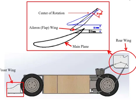
According to [3], DRS are adjustable rear wings used in Formula One cars for
facilitate overtaking only. The DRS consists of two elements which is the main plane and
the flap. The main plane remains fixed and the flap is adjustable which able to pivot
between 10mm to 50mm from the main plane. DRS can be activated and deactivated
depending on several conditions. When the DRS is activated, the flap wing at 50mm
distance from main plane and when disabled, the flap wing returns to original position,
10mm from main plane as shown in Figure 1.1. However, DRS can be activated only for
overtaking in a straight line condition. When the flap wing at 10mm position from main
plane (DRS deactivate), the air stream ideally connected with wing contours and without
any turbulence as shown in Figure 1.2. This provides the car with full of downforce
efficiency and improving level of grip (stability). At the 50mm away from the main plane
(DRS activate), both wings stop acting in harmony and airflow around the wing separated
as shown in Figure 1.3. This condition decreasing the effectiveness of the wings
(downforce decrease) and reduce drag force, but in the same time improving the straight
line speeds of the car. Decrease in downforce can cause the handling to change from
understeer to oversteer (car losing stability). This is the reason why DRS only can be
activated during overtaking in straight line but not in cornering condition. During high
3
Figure 1.1: Drag Reduction System
Figure 1.2: DRS deactivated [3]
Figure 1.3: DRS activated [3] Front Wing
Rear Wing Center of Rotation
4
This project is about a drag reduction system (DRS) for go-kart. The rear wing
DRS capable to improve the straight line speed of race car. The front wing aerodynamic
design allows increasing the downforce of the race car. This system capable to reduce the
aerodynamic drag force to generate more stream line speed and improve car’s handling
stability. This DRS has two set of aerofoil (main plane and flap wing) connected to each
other by the wing endplate and an actuator. The flap (aileron) wing can rotate only
between 10mm to 50mm from the main plane. The flap rotate by using actuator that
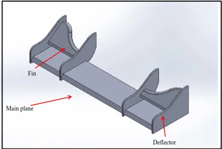
control by the driver. The front wing, which is responsible to produce downforce consist of
deflector, fin, and main plane as shown in Figure 1.4.
Figure 1.4: Front Wing
. The front and rear wing are designed by using Solidworks software. The
aerodynamic flow motions of this wing are simulated by using Solidworks Flow
Simulation software to yield aerodynamics forces and coefficients. These wings are built
using PVC foam. The actuator to actuate the flap wing is controlled by using on/off control
circuit.
Deflector Fin
5
1.2 Problem Statement
The purpose of DRS is to improve speed of a race car during overtaking situation.
However, there are two enemies of speed in race car aerodynamics which is excess in drag
force and lack of downforce. These two forces are the main constrain in every race car in
order to achieve top speed. The drag is the resultant force in the direction of the upstream
velocity [5], it opposes the forward motion of the vehicle. Excess in drag (wind resistance)
reducing the effectiveness of the time and required more engine horsepower to achieve top
speed. Lack of downforce can reduce the traction and road grip [3]. This reduction on tire
traction can be very dangerous during the race car is braking or cornering. Oversteers will
occurs if there is little grip at the rear of the car compare to the front. The main problem in
aerodynamic design of a race car is how to provide sufficient downforce as well as
minimum aerodynamic drag. Therefore, the current concern in this project is about on
how to balance the downforce and aerodynamic drag. In order to balance these forces, a
fundamental engineering knowledge of aerodynamics is essential as well as the downforce
and drag force theories.
1.3 Objectives
The objectives of this project are listed as follows:
1. To study aerodynamic front and rear wings for go-kart in term drag force and
downforce.
2. To develop the go-kart Drag Reduction System (DRS) and test its performance
in term of aerodynamics element (drag force, downforce, drag coefficient,
downforce coefficient) using simulation software and static test (real world
test).
6
1.4 Scopes
The scopes of the project are summarized as follows:
1. This study concentrates on front and rear wings only and does not include study
into other aerodynamic devices such as diffusers, venturies and body part.
2. Testing of the wings is limited to the analysis using Solidworks Flow simulation
software and static test only.
3. The development of adjustable/actuated wing (DRS) only for the rear wing.
4. This study does not include material study or constructability analysis.
Manufacturing consideration will be ignored in this study.