UNIVERSITI TEKNIKAL MALAYSIA MELAKA
AUTOMATIC PART FEEDER
This report submitted in accordance with requirement of the Universiti Teknikal Malaysia Melaka (UTeM) for the Bachelor Degree of Manufacturing Engineering
(Robotic and Automation) with Honours.
by
MUHAMMAD HELMI BIN JAMIL
UNIVERSITI TEKNIKAL MALAYSIA MELAKA
BORANG PENGESAHAN STATUS LAPORAN PROJEK SARJANA MUDA
TAJUK: AUTOMATIC PART FEEDER
SESI PENGAJIAN: 2009/ 10 Semest er 2
Saya MUHAMMAD HELMI BIN JAMIL
mengaku membenarkan Laporan PSM ini disimpan di Perpust akaan Universit i Teknikal Malaysia Melaka (UTeM) dengan syarat -syarat kegunaan sepert i berikut :
1. Laporan PSM adalah hak milik Universit i Teknikal Malaysia Melaka dan penulis. 2. Perpust akaan Universit i Teknikal Malaysia Melaka dibenarkan membuat salinan
unt uk t uj uan pengaj ian sahaj a dengan izin penulis.
3. Perpust akaan dibenarkan membuat salinan laporan PSM ini sebagai bahan pert ukaran ant ara inst it usi pengaj ian t inggi.
4. **Sila t andakan (√)
SULIT
TERHAD
TIDAK TERHAD
(Mengandungi maklumat yang berdarj ah keselamat an at au kepent ingan Malaysia yang t ermakt ub di dalam AKTA RAHSIA RASMI 1972)
(Mengandungi maklumat TERHAD yang t elah dit ent ukan oleh organisasi/ badan di mana penyelidikan dij alankan)
DECLARATION
I hereby, declared this report entitled “Automatic Part Feeder” is the results of my own research except as cited in references.
Signature : ……….
Author’s Name : ………
APPROVAL
This report is submitted to the Faculty of Manufacturing Engineering of UTeM as a partial fulfillment of the requirements for the degree of Bachelor of Manufacturing Engineering (Manufacturing Process) with Honours. The member of the supervisory committee is as follow:
ABSTRACT
ABSTRAK
DEDICATION
Specially dedicated to
my beloved parents and family who have encouraged,
guided and inspired me throughout my
ACKNOWLEDGEMENTS
TABLE OF CONTENT
2.2 Previous Work and Research 4
2.2.1 Part Feeder In Automated Assembly 4
2.2.2 Importance of Part Feeder 6
2.2.3 Flexible Part Feeding 7
2.2.4 Important Factor for Part Feeder 8
2.2.5 Types of Part Feeder 9
2.2.5.6 Revolving-Plate Feeder 13
2.2.5.8 Linear Feeder 15
2.2.5.9 Vibratory Part Feeder 15
2.2.6 Sensors 18
2.3 Related Works 19
2.3.1 Design and Fabrication of an Agile Sorting and Feeding System 19 2.3.2 Novel Design and Development of An Active Feeder 20 2.3.3 A Methodology for Part Feeder Design 21
2.4 Conclusion 23
3 METHODOLOGY 24
3.1 Introduction 24
3.2 Planning Stage 24
3.2.1 Gantt Chart 25
3.2.2 Methodology Flowchart 26
3.3 Research Related to Project 27
3.4 Design Stage 28
3.5 Software Used 29
3.6 Material Selection 31
3.6.1 Aluminum Profile for Structure 31
3.6.2 Aluminum Sheet for Feeder 32
3.6.3 Electrical/Electronic Component 34
3.6.3.1 Microcontroller 34
3.6.3.2 Sensor 36
3.6.3.3 Relay 37
3.7 Testing and Analysis 37
3.8 Preliminary System Design 38
3.81 Sketch 38
3.82 System Block Diagram 39
4 DESIGN AND DEVELOPMENT 40
4.1 Introduction 40
4.3 Part Feeder Electronic Circuit Development 44
6 CONCLUSION AND FUTURE WORK 66
6.1 Conclusion 66
6.2 Future Work 67
REFERENCES 68
LIST OF TABLES
2.1 Functions of feeder 15
3.1 Gantt chart for PSM 1 and PSM 2 24
3.2 Static friction coefficent of aluminum against other material 32 3.3 Static coefficent of steel against other material 32
4.1 Output pins and motor direction 48
LIST OF FIGURES
2.1 Friction on incline track 8
2.2 Barrel feeder 9
2.3 Centrifugal feeder 10
2.4 Drum feeder 10
2.5 Shaker feeder 11
2.6 Roll feeder 12
2.7 Revolving-plate feeders 12
2.8 Gravimetric feeder 13
2.9 Linear feeder 14
2.10 Vibratory part feeder 14
2.11 Fabricated setup of agile feeder 18
2.12 Developement of an active feeder 19
2.13 Feeder design flowchart 21
3.1 Methodology flowchart 26
3.2 Design flowchart 28
3.9 PIC16F877 microcontroller 35
3.10 Limit switch 36
3.11 Relay 37
3.12 Automatic part feeder sketch 38
4.1 Design of part feeder 40 4.11 Circuit simulation using Proteus ISIS 7 44 4.12 Red LED is ON when the two switches is OFF 45
4.13 Green LED is ON when switch 1 is ON 45
4.14 Real electronic circuit 45
4.15 Operational flowchart for automatic part feeder 47
4.16 New project in mikroC 49
4.17 Select P16F877A as the device 50
4.18 Write the programming 50
4.19 Success build in mikroC 51
4.20 PIC burner 51
4.21 PICkit 2 programmer 52
4.23 Hex file successfully imported 52
4.24 Write programming 53
4.25 Programming successful 53
5.1 Automatic part feeder prototype 55
5.2 18º angle of incline feeder track 56
5.3 Design showing the angle of the incline track 56
5.4 Feeder with limit switch station 56
5.5 Red LED indicate feeder is OFF 57
5.6 Green LED indicate feeder is ON 57
5.7 Electronic circuit of part feeder 57
5.9 Adjustable feeder wall 58
5.10 Feeder width of 4.5 cm 58
5.11 Feeder width of 4 cm 58
5.12 Electronic testing 59
5.13 Voltage supply to relay 59
5.14 9V battery length and width 60
5.15 9V battery height 60
5.16 Feeder gate holding down part from going down the track 61 5.17 Top view of part being hold by feeder gate 61
5.18 Part sliding down to the station 61
5.19 Part arrive at the station 62
5.20 Part on upper feeder 62
5.21 Feeder gate releasing one part 62
5.22 Incline surface angle and dimensions 63
LIST OF ABBREVIATIONS
PC - Personal Computer MC - Microcontroller DC - Direct Current AC - Alternating Current
CHAPTER 1
INTRODUCTION
1.1 Background
Parts feeders are machines that feed parts so that robots or other automated processes can capture and use or package the parts or components. Applications range from packaging pills in the pharmaceutical industry to sparkplug production in the automotive industry. The main difference between parts feeders is their method of directing the feed. The purpose of this project is to create an automatic part feeder for pressing machine. This feeder will direct the part into the machine with the right orientation. Operator will put the parts into the part feeder with large volume and the feeder will let the part move one by one into the pressing machine. Automation nowadays is a must for a manufacturing factory as it provides many benefits. The advantages of part feeder to manufacturing nowadays as it reduce cost where factory will not have to pay for operator. By using part feeder also it will increase the manufacturing productivity because it reduces time and cost.
1.2 Problem Statement
Nowadays, automated manufacturing needs are changing from large-volume, single-product runs to small-size, customer-specific lots. There is also a continuing pressure for higher quality, lower cost, and shorter design cycles.
The parts for the pressing machine need to be inserted manually by operator, so there is no safety element. The hands of the operator might be pressed by the pressing machine while inserting the part. To avoid any accident, this automatic part feeder will replace the inserting part job with the feeder feeding the part automatically to the pressing machine.
With the use of operator to insert the part and at the same time to control the pressing machine is quite hard. So with this automatic part feeder, it is easier to use. The operator will just put the part into the part feeder in large volume, and the feeder will let go the part one by one, so operator just have to control the pressing machine and not to repeat inserting the part into the machine.
1.3 Objectives
The objectives of the project are:
a) To develop an automatic part feeder for pressing machine.
b) To added safety element to the pressing machine to avoid any accident.
c) To create a cheaper and easier to use part feeder than the normally part feeder that is available in the market.
1.4 Scope of project
In order to complete this project, the following tasks are required:
a) Design the part feeder mechanical structure. b) Develop the prototype of the feeder.
c) Program the feeder using microcontroller. d) Test and analysis.
CHAPTER 2
LITERATURE REVIEW
2.1 Introduction
This chapter reviews some of the previous works that have been done in the field of feeder technology. This section highlighted the needs of part feeding in automated assembly systems, the common applications of automatic feeder, types of conveying in part feeder, analysis on the part feeding system as well as design of effective traps for a typical type of part feeder.
2.2 Previous Work and Research
2.2.1 Part Feeder in Automated Assembly
Nowadays industrial sector have been using automated assembly line which come in bulk, so the use of part feeder is essential as it will orientiate and transport the part. Some of the previous work will be discussed to support the need of the part feeder.
The components are usually joined one at a time and are completed progressively. An automated assembly system consists of the following subsystem:
a) One or more workstations at which the assembly steps are performed.
b) Parts feeding devices that deliver the individual components to the workstations. c) A work handling system for the assembled product.
Prior to starting any automation project, it is important to set goals and determine why the automating process is necessary Philip (1998). The following are the few possible reasons:
a) Increase productivity
Many times the use of automation will allow an operator to perform more than one task. In other situations, the automation device can actually assist in an operation, resulting in increased productivity.
b) Labor savings
Automation usually performs tasks that are very repetitive,which can lead to fatigue and boredom if performed manually. Automation can free a worker to perform additional, more highly-skilled assembly functions. One type of automated parts handling system consists of a storage supply hopper, vibratory parts feeder, an in-line track, and a part placing device. This system reduces the requirement for a full time employee to hand load the machine. Assuming one shift operation, payback for this system would be less than one year. In multiple shift operations, payback can be little as four months.
c) Quality
Automation can lead to increased consistency and quality. In general, automatic systems require a higher quality supply of parts than that required for hand assembly.
d) Safety
Before any automated solution to be considered, focused attention must be given to the part. The shape, size, weight, composition and condition of the part must be evaluated to determine if an automated solution is achieveable. To effectively feed and orient a part, the shape of the part must be consistent so that an orientation method can be properly design. Quality of the part handled is very important success to part feeding. Part size and weight also play a big role in the evalution process of part feeding. The equipment size will determined by the part size, feed rate, complexity of part shape, as well as part compostion .
2.2.2 Importance of Part Feeder
The importance of part feeder is to maximize productivity in industry in order to satisfy increasing labour cost and increasing demand for finished goods. In his proceedings, Natarajan (2007), points out that assembly accounts for up to 50% of the total manufacturing cost so it is quite mandatory that we opt for a mechanized assembly. It shows that we should use other method because assembly will cost alot and then we have to pay for the workers. By this, part feeder became and important solutions, where cost of workers can be cut.
2.2.3 Flexible Part Feeding
Automated manufacturing needs are changing from large-volume, single-product runs to small-size, and customer-specific lots according to Branicky et.al. (1999). This shows that factory doesn’t need a big and flexible part feeder that can orient all part and feed it to one machine, but the growing needs of small and cheaper part feeder is higher. Moreover, a continuing pressure for higher quality, lower cost, and shorter design cycles for part feeder makes one lot-specific part feeder more better than the flexible part feeder that can feed many part. However as it can feed many part, it will also decrease the feed rate and thus make the feeding process slower than the one lot-specific part feeder.
Sprovieri (2004) discussed about flexibility in automated assembly operations. Usually, manufacturing engineers would like to feed part A today, part B tomorrow and part C next month. But, when they realize that such flexibility will decrease the feed rate and increase the cost and complexity of the system, suddenly flexibility doesn't seem like such a good idea. Flexibility involves three of the manufacturing biggest needs which are automating more processes, reducing changeover time, and spreading the cost of equipment investment over multiple products. This shows that flexibility is depends on what the company needs, if the company produces variety of product and want the equipment cost to be low, the use of flexible part feeder is important, but then, if the company only produces two or three product, the needs of flexible part feeder is lower as the one lot-specific feeder gives you lower cost, shorter design cycle and a better quality.
2.2.4 Important Factor for Part Feeder
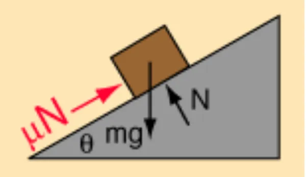
To build an automatic part feeder, speed, flexibility and ease of integration must all be considered according to Weber (2001). However the method to use to build the part feeder depends on part configuration and its complexity. Variables such as size, shape, density and material will determine how effectively a part can be positioned. The speed of the part depends mostly from the inclined surfaces of the part feeder. The coefficient friction of the incline surface on the part feeder will also affect the speed of the part going through the part feeder. So the use of the right material is important for the part feeder. The friction between part and the surface of the feeder must be low to prevent part from damage or scratch because of the friction.
Figure 2.1: Friction on incline track
Where, θ - angle of inclination of track m - mass of part