Procedia Engineering 68 ( 2013 ) 251 – 257
1877-7058 © 2013 The Authors. Published by Elsevier Ltd.
Selection and peer-review under responsibility of The Malaysian Tribology Society (MYTRIBOS), Department of Mechanical Engineering, Universiti Malaya, 50603 Kuala Lumpur, Malaysia
doi: 10.1016/j.proeng.2013.12.176
ScienceDirect
The Malaysian International Tribology Conference 2013, MITC2013
Experimental and Numerical Investigation of SUP12 Steel Coil
Spring
Mohd Izaham Zainal Abidin
a,b, Jamaluddin Mahmud
a, Mohd Juzaila Abd Latif
c,
Aidah Jumahat
aaFaculty of Mechanical Engineering, Universiti Teknologi MARA, 40450 Shah Alam, Selangor, Malaysia
bSapura Industrial Berhad, Kawasan Perindustrian Bangi, 43650 Bandar Baru Bangi, Selangor, Malaysia
cFaculty of Mechanical Engineering, Universiti Teknikal Malaysia Melaka, 76100 Durian Tunggal, Melaka, Malaysia
Abstract
Coil springs made of spring steel often have high yield strength which enables them to return to their original form after a significant force is applied. Specific application of steel spring in automotive is ruled by industrial guideline, for example, Japanese Industrial Standard (JIS), Daewoo Engineering Standard (EDS) and Daihatsu Technical Standards (DTS). This study attempt to investigate the characteristics of a coil spring type used in automotive i.e. SUP12 where the analysis approach was done systematically using experimental and numerical methods. The experimental part was intended to verify the SUP12 springs material properties (spring constant, yield strength and tensile strength) are within standard for spring steels, JIS G 4801(1984). The SUP12 spring underwent tensile testing in accordance to JIS Z 2201(2010). Later, finite element simulation was performed using HYPERWORKS (Ver. 11) software to predict the steel spring under displacement conditions as per specific customer requirement i.e. at full rebound, curb length and full bump. The resulting experimental data indicates that the tested SUP12 passed the minimum requirement as per standard. On the other hand, finite element results show that the spring meets the customer requirement within small deviation. This suggested that the systematic verification by experiment and numerical analysis approach on such spring is practical by spring maker.
© 2013 The Authors. Published by Elsevier Ltd. Selection
Selection and peer-review under responsibility of The Malaysian Tribology Society (MYTRIBOS), Department of Mechanical Engineering, Universiti Malaya, 50603 Kuala Lumpur, Malaysia.
Keywords: "coil spring, SUP12, tensile test, finite element, HYPERWORKS"
Nomenclature
E Young's modulus (MPa) S tensile strength Sy yield strength Greek symbols
ρ density
ν Poisson’s ratio
© 2013 The Authors. Published by Elsevier Ltd.
1.Introduction
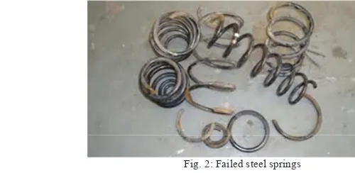
A coil spring, also known as a helical spring (Fig. 1), is a mechanical device which is typically used to store energy and subsequently release it, to absorb shock, or to maintain a force between contacting surfaces[1]. Generally, they are made of an elastic material formed into the helical shape which returns to its initial length when unloaded. Spring steel is an alloy, consists of either low, medium or high carbon content with very high yield strength [2]. This allows coil spring made out of spring steel to return to their original shape despite of large magnitude of bending or twisting. In addition to its already impressive properties, steel springs are often heat treated. The process includes heating, quenched, and finally tempered as enhancement to withstand heavy application such as in automotive sector. Some of the problems that may occur to a coil springs are out of stiffness and low fatigue life. Fig. 2 below shows the common failure type that occurs on a spring. Failure analysis of spring is the main concern of auto-parts maker and usually caused by insufficient load-carrying capacity, raw material defects, manufacturing defects and due to complex stress distribution [3]. Therefore, specific guidelines are available for the manufacturing of coil spring type that requires fatigue stiffness and toughness to high stress. One type that is widely used is silicon chromium steel. The spring is designated as SUP12, of which Japanese Industrial Standards (JIS), Daewoo Engineering Specs (EDS) and Daihatsu Technical Standards (DTS) are referring to [4, 5, 6]. The standards above regulate the mechanical properties of the spring but each of them differs in the minimum tensile strength, allowable elongation, contraction and hardness range.
Fig. 1: Coil type steel spring Fig. 2: Failed steel springs
While the previous standards rule out the minimum magnitude and tolerance, automakers or customers are usually demand for higher requirement. These customers requirement may diverse from each other, and thus necessitate for a quick way to test and verify a particular coil spring. One way of doing this is by using computer aided engineering (CAE) or finite element method (FEM). Experimental method has limited properties that can be gained from and some of the customers' requirements might not be acquired. Therefore, the use of CAE or FE software as verification procedure helps designers prior to prototyping coil springs. Main reason of using finite element analysis (FEA) in coil design is to minimize error by simplification of equations [3,7]. For example, buckling equations of isotropic helical springs loaded axially consist of twelve linear equations. Analytical procedure is too tedious and requires numerical implementation in exact manner [8]. However, due to the nature of FEM that relies on assumptions and simplification, the generated result would not be accurate [3]. Nevertheless, the result is often approximated and capable of reducing enormous design time.
In finite element modelling (FEM), helical spring in compression is represented by a simple stiffness matrix element as explained by Kelly and Knight [9]. The stiffness matrix of an isotropic beam element is defined by its cross sectional area, area moments of inertia, torsional constant elastic modulus and modulus of rigidity. One or more of these may be applied to best approximate the desired spring stiffness matrix. In a study by Watanabe et al., FEM analysis on the beam element of actual spring was compared to its experimental stress measurement [10].
2.Methodology
The systematic approach to validate the SUP12 spring is by first experimental tensile testing of coil spring and later numerical procedure by the means of FE software i.e. HYPERWORKS (Ver. 11, licensed under Sapura Technical Centre).
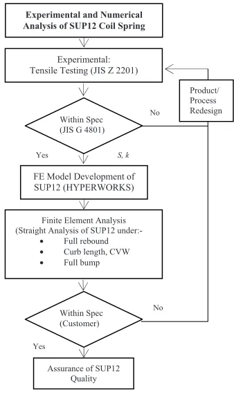
. SUP12 spring's additional exact materials property i.e. tensile strength, S from the experiment will be used as input in FEM for customer specification conformity. Supposedly in industry, if the spring does not passed at any of those test, material or the manufacturing process should be reviewed or re-design to come out with SUP12 spring that comply to both requirement. The overall procedure of the study (as in Figure 3) is comprises of main stages as described below:-
• Tensile testing of coil spring
• FEA of SUP12 spring in compression
The study material of interest is steel spring type SUP12, specification grade from JIS G 4801: Spring Steels [4]. It is a relatively high strength silicon-chromium steel coil spring that is purposely used as automotive suspension. SUP12 is equivalent to AISI 9254. Table 1 and Table 2 show respectively the coil dimension and material properties of SUP12 for the current study according to industrial standards i.e. JIS G 4801.
Table 1. SUP12 Coil Dimension
SUP12 Coil Dimension Value
Bar Diameter (mm) 11.05
Bar length (mm) 2645.10
Spring Inner Diameter (mm) 80.00
Spring Outer Diameter (mm) 102.10
Mean Diameter (mm) 91.05
No. of coils 9.18
Free length (mm) 308.9
Fig. 3: Verification of SUP12 spring proposed for current research Table 2. Material properties of steel spring, SUP12 sample and its
specification as per JIS G 4801
Material Properties JIS G 4801
Density, ρ (tons/mm3) 7.85 E-9
Young's Modulus, E (GPa) 207
Poisson's ratio, ν 0.28
Tensile Strength, S (MPa) Min 1226
Yield Strength, SY (MPa) Min 1079
Elongation (%) Min 9.0
2.1.Experiment: Steel Spring Tensile Testing
Physical testing on the spring in tension is done as accordance to Tensile Testing JIS Z 2201(2010) [11]. The testing was done by 10-tonne universal testing machine, UTM as in Fig, 4 (a) below. It was made by ACT Technology (South Korea) and is operated by using ActimPro software.
Number of coil spring that is used for testing is one piece. The tested spring was mounted both on top and bottom, at specially made seats (see Fig. 4 (b)). Results produced from the testing i.e. spring constant, maximum force, elongation and tensile strength, are to be verified for their particular specification conformity. Value of tensile strength will be referred for the FE model development in the next stage.
(a) (b) Fig. 4: (a) UTM machine used in the study and (b) its top seat to mount the spring
2.2.Finite Element Analysis of SUP12 Spring in Compression
The study is limited to only straight analysis of spring where only vertical loading and displacement are assumed to take place. The analysis of steel spring is focusing on its compressibility performance at three conditions i.e. full rebound, curb length and full bump. Curb length and full bump conditions resemble maximum load and ultimate tensile strength respectively. The FEA was performed using HYPERWORKS (Ver. 11) as the solver, licensed under Sapura Technical Centre.
3D FE Model Development of SUP12
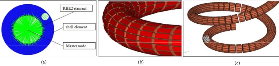
The SUP12 coil spring is replicated by using HYPERWORKS software. It is an integration of 1-D, 2-D and 3-D element meshing as shown in Fig. 5. RBE2 element type (1-D) was used for the upper and lower seat of spring model to constrain and distribute force equally from master node (centre axis) to all other nodes. QUAD4 mesh element (2-D) was applied as shell or skin element to 'capture' accurately the stress generated from the main body of spring which a HEXA8 type 3-D element. Total number of nodes and element of the model are 10898 and 12758 respectively. Apart from other properties that are available in previous Table 2, spring's tensile strength of 1728 MPa from the previous tensile test results are used for the FE model material properties input.
Fig. 5: Meshing procedure on spring model (a) RBEA (1-D), (b) QUAD4 (2-D) as red skin and (c) exploded view of spring as HEXA8 (3-D)
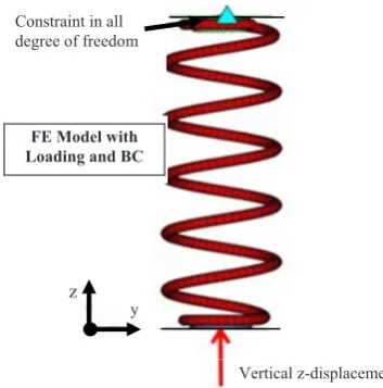
Boundary and Loading Condition
Developed model is shown in Fig. 6. The analysis was mimicking the coil spring on-the-road condition where top seat was set as fixed (degree of freedom, DOF = 0) while lower seat was given imposed displacement in z-direction, with respect to time (transient analysis). The displacement is set by certain condition by a customer (undisclosed automaker) as in Table 3. Maximum load at curb length or compression at 221.1 mm was set to 1470 ± 75 N and maximum stress at full bump should be below 1260 MPa, much higher than JIS specification (1226 MPa). In addition, the maximum stress should not be exceeding the ultimate tensile strength of raw material of SUP12 i.e. 1800 MPa [4].
Table 3. Example of condition by customer requirement
Fig. 6: FE model with loading and boundary condition
Results and Discussion
Results of SUP12 tensile testing are shown in Table 4 and compared to its JIS specification. The theoretical maximum strain is 0.0086 while the tensile test revealed SUP12 has a yield strength and tensile strength of 1356 N/mm2 and 1728 N/mm2 respectively. Both results are beyond the specification by 25.67% and 40.95% respectively. Also, the tested SUP12 records 13.5% of elongation and exceeds 50% of the minimum value (9.0%). Thus, it is clearly that SUP12 spring superiorly complies to the JIS 4108 standard. However, the number of test sample is insufficient due to part's cost. In case of mass manufacturing, number of test pieces should be sampled out from the production line to assure the quality. On the other hand, the SUP12 is yet to meet the customer's specification provided.
Condition Value Maximum Load at Curb Length, CVW @
221.1 mm (N) 1470 ± 75
Spring Stiffness, k (N/mm) 25 ± 1.47
Maximum Stress at Full Bump (MPa) < 1260
Vertical z-displacement Constraint in all
degree of freedom
FE Model with Loading and BC
z
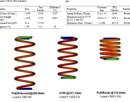
Fig. 7: FEA simulation of SUP12 spring on three displacement conditions i.e. full rebound, CVW and full bump
Figure 7 shows the simulation done in HYPERWORKS to analyze the functioning condition under full rebound, curb length and full bump. Full rebound is the state where the spring recovers to its unloaded length. CVW is the curbed spring when it is fitted to an auto suspension system where the pre-load is the whole body of car (1458.2 N). Maximum loading (3631.3 N) on a car would lead to maximum compression of spring to 114.9 mm. As for validation, Table 5 presents the summary of FEA simulation results as compared to the specific customer requirement. The maximum stress recorded is 1011.0 MPa, within the specification range and below the actual tensile strength of SUP12 which is 1728 MPa. CVW load from simulation is within the requirement range i.e. 1458.2 N. The stiffness rate calculated from the load-displacement plot is predicted as 20.63 N/mm, lower by 1.79% to the nominal but is within the specified range.
From both actual testing and FEA simulation, the SUP12 spring conforms both JIS G 4801 and customers specification. In real industry practice, conforming by the means of FEA or CAE should be succeeded by actual compression of springs in full suspension system. Any incompliance should be addressed by the supplier/manufacturer's design department for any redesign in product or process as shown in research flow chart (Fig. 3).
Table 4. Summary of tensile test on SUP12 coil spring results as compared to JIS G 4801 standard.
Properties Spec Results Test Difference (%)
Yield Stress (N/mm2) 1079 1356 25.67
Tensile Strength
(N/mm2) 1226 1728 40.95
Maximum Force (kN) N/A 173.95 -
Elongation (%) 9.0 13.5 50
Table 5. FEA simulation result summary as compared to customer spec.
Properties Customer Spec Results FEA Remarks
Spring Stiffness (N/mm) 21 ± 1.47 20.63 Passed Maximum Load at CVW
Conclusion
The experimental tensile testing to confirm the compliance of SUP12 spring towards JIS 4108 has been performed successfully. Later, employment of numerical analysis using commercial software (HYPERWORKS) to validate the SUP12 as per customer requirement has been accomplished. With the actual spring tensile strength of 1728 N/mm and elongation of 13%, the SUP12 coil spring actually passed beyond the JIS standard and fulfils the customer specification.
Completion of the study would benefits in development and designing phase of an automotive coil spring where designers have to fulfil both requirement from industrial standard and customers' quality need. The study could be further research on how reliable the FE modelling of tensile test as compared to actual testing results. If any discrepancy is found, the FE model can be improved by including other material properties or refinement of 3D element in term meshing, size and etc.
References
[1] Adetunji, O. R., Alao, M. J., 2012. The Influence of Annealing Temperatures on the Ductility and Toughness of Springs, The Pacific Journal of Science and Technology 13, p. 63-66.
[2] Boker's Inc., Spring Steel Metal Stamping, Website: http://www.bokers.com/spring_steel_metal_stampings.asp
[3] Prawoto, Y., Ikeda, M., Manville, S. K., 2007. "Failure Analysis of Automotive Suspension Coil Springs," 2007 AIST Steel Properties & Applications Conference, Detroit, Mich.
[4] JIS G 4801, Spring Steels, 1984. Japanese Industrial Standard. [5] EDS-M-1801, Spring Steels, 2003. General Motor Standard. [6] DTS G 3500G, SPring Steels, 1995, Daihatsu Technical Standard.
[7] Prawoto, Y., Ikeda, M., Manville, S. K., Nishikawa, A., 2008. "2007 AIST Steel Properties & Applications Conference", Detroit, U, S, A, pp. 35-48.
[8] Sacma, S., 2009. Estimation of the Buckling loads of Helical Coil Springs with the Help of Neural Networks, Unpublished Msc Thesis, Dept. of Mechanical Eng, Cukurova University.
[9] Kelly, A. D., Knight, C. E., 1992. "Helical Suspension Springs in Finite Element Models of Compressors," International Compressor Engineering Conference, paper # 870.
[10]Watanabe, K., Yamamoto, H., Ito, Y., Isobe, H., 2007. "Simplified Stress Calculation Method for Helical Spring,." Proceeding of Advanced Spring Technology JSSE 60th Anniversay International Symposium, paper#4.