DESIGN AND EVALUATE THE PERFORMANCE OF MY 2ND EYE BY USING ULTRASONIC SENSOR
Tin Shaw Liang
i
“ I hereby declare that I have read through this report entitle “DESIGN AND EVALUATE THE PERFORMANCE OF MY 2nd EYE BY USING ULTRASONIC SENSOR” and found that it has comply the partial fulfilment for awarding the degree
of Bachelor of Mechatronics Engineering”.
Signature : ...
Supervisor’s Name : ...
ii
DESIGN AND EVALUATE THE PERFORMANCE OF MY 2nd EYE BY USING
ULTRASONIC SENSOR
TIN SHAW LIANG
A report submitted in partial fulfilment of the requirements for the degree of Bachelor of Mechatronics Engineering
Faculty of Electrical Engineering
UNIVERSITI TEKNIKAL MALAYSIA MELAKA
iii
I declare that this report entitle “Design And Evaluate The Performance Of My 2ND Eye By Using Ultrasonic Sensor” is the result of my own research except as cited in
the references. The report has not been accepted for any degree and is not concurrently submitted in candidature of any other degree.
Signature : ...
Name : ...
iv I dedicate this research work to my supervisor, Mr. Anuar bin Mohamed Kassim who teach and guide me, to my family who supports me in everything and to my friends who helped
v
ACKNOWLEDGEMENT
First of all, I would like to thank my beloved supervisor Mr. Anuar Bin Mohamed Kassim for giving the support morally and physically and shared his expertise and knowledge with me. He always guides me to explore some new idea in my project and solution for difficult problem.
I am highly indebted to panels, Mr. Syed Mohamad Shazali Bin Syed Abdul Hamiddan Dr. Muhammad Fahmi bin Miskon who have provided me the valuable
suggestion and good support before my presentation.
I owe a debt of thanks to all those time, concern and efforts were given during the process of completing this report. I am thankful to everyone who always inspires me directly and indirectly during my FYP .
vi
ABSTRACT
vii
ABSTRAK
viii
TABLE OF CONTENTS
CHAPTER TITLE PAGE
1. ACKNOWLEDGEMENT V
2. ABSTRACT VI
3. ABSTRAK VII
4. TABLE OF CONTENTS VIII
5. LIST OF TABLES X
6. LIST OF FIGURES XI
7. LIST OF SYMBOLS AND ABBREVIATIONS XII
8. INTRODUCTION 1
1.1 Project Background 1
1.2 Problem Statement 2
1.3 Objective 2
1.4 Scope 2
9. LITERATURE REVIEW 3
2.1 GuideCane 3
2.2 An Ultrasonic Navigation System for Blind People 5
2.3 A Low Cost Artificial Vision System for Visually Impaired People 6
2.5 Product Comparison 8
2.6 Sensor Comparison 11
ix
2.6.2 GP2Y0A21YK (Infrared Distance Sensor) 12
2.6.3 OADM 250 (Laser Sensor) 13
10. METHODOLOGY 17
3.1 Lab Test 24
3.1.1 Experiment 1 24
3.1.2 Experiment 2 26
3.2 List Of Components 27
11. RESULTS AND ANALYSIS 29
4.1 Experimental 1 Result 29
4.1.1 Data Analysis of Experiment 1 31
4.2 Experiment 2 Result 32
4.2.1 Data Analysis of Experiment 2 32
12. DISCUSSION OF RESULTS 33
5.1 Discussion 33
13. CONCLUSION AND RECOMMENDATION 34
6.1 Conclusion 34
6.2 Recommendation 34
x
LIST OF TABLES
TABLE TITLE PAGE
2.1 Pair Wise Comparison Table Of The Product’s Criteria 8
2.2 Weighted Objective Table For The Products 9
2.3 Point Explanation 9
2.4 Technical Specifications Of Ultrasonic Distance Sensor 11
2.5 Technical Specifications Infrared Distance Sensor 12
2.6 Technical Specifications Of Laser Sensor 13
2.7 Pair wise Comparison Table Of Sensor’s Criteria 14
2.8 Weighted Objective Table For The Sensors 15
2.9 Point Explanation 15
xi
LIST OF FIGURES
FIGURE TITLE PAGE
2.1 The User Avoid Obstacles 4
2.2 The Block Diagram Of The System 5
2.3 The Navigation Aid Worn By The Blind 6
2.4 The System Block Diagram 7
2.5 Hardware Setup 7
2.6 Ultrasonic Distance Sensor 11
2.7 Infrared Distance Sensor 12
2.8 Laser Sensor 13
3.1 K-Chart 18
3.2 Project flowchart 19
3.3 System Flowchart and Pseudocode 20
3.4 Overview of The Casing for Ultrasonic Sensors. 21
3.5 Overview of My 2nd Eye (A: New Version; B: New Version) 22
3.6 Right Angle of Theorem Pythagoras 23
3.7 Side View of My 2nd Eye 23
3.8 Experiment 1 Equipment Used. 25
3.9 Experiment 1’s Path Layout 25
3.10 Hardware Setup For Experiment 2 26
3.11 Project Gant- Chart 28
4.1 Graph of Left Sensor's Distance Reading Versus Distance of Path 29
4.2 Graph of Front Sensor's Distance Reading Versus Distance of Path 30
4.3 Graph of Right Sensor's Distance Reading Versus Distance of Path 30
4.4 Graph of Bottom Sensor's Distance Reading Versus Distance of Path 31
4.5 Graph of Ultrasonic Sensor’s Accuracy Versus Voltage Level of
Battery
xii
LIST OF SYMBOLS AND ABBREVIATIONS
1 CHAPTER 1
INTRODUCTION
1.1 Project Background
According to the organization of the United Nations (UN) has been released the statistic that people with disabilities (PWDs) in the world are 10% percent of the total population in year 2010 [1]. The population of visually impaired person in Malaysia is 2.44% of total population of Malaysia. Besides that, the number of blind people in Malaysia is 0.2% of total resident. By seen this statistic, the percentage of visually impaired person and blind person is not so much. However, based on the 2010 population Census, total resident of Malaysia achieved 28.3 million peoples, which means Malaysia had 0.69 million visions impaired peoples and 56.6 thousand blind people [2]. These results show that this amount of people needs more support and care from the community. This phenomenon gave birth to the first researched and
developed device for the visually impaired person which is called My 2nd Eye had been
2
1.2 Problem Statement
There are several problem need to be solved along this project. First of all, we need to carry out some experiment to compare the characteristic of infrared sensor and
ultrasonic sensor. After that, a new method should to be applied in order to replace the infrared sensor used in previous version of My 2nd Eye with ultrasonic sensor. Then, a new
casing needs to be designed to place the ultrasonic sensor. Thus, there are several aspect need to be considered in the design to make has an aesthetic value:
Accuracy of ultrasonic sensor within 1.0 to 1.5 meter.
Number of ultrasonic sensor has to be used.
The size of new designed casing for ultrasonic sensor that can make the design has an aesthetic value.
1.3 Objective
The objective of this project is to improve the performance of the previous My 2nd
Eye by using ultrasonic sensor as the system’s input.
1) To design and develop the obstacle detection system by using ultrasonic distance sensor and PIC microcontroller.
2) To analyze the efficiency of ultrasonic sensor for obstacle detection.
3) To determine the effect of the voltage drop on the accuracy of the ultrasonic sensor.
1.4 Scope
Design an obstacle detection system by using four ultrasonic sensors that are able to detect the obstacle within 1.5 meter in four directions (front, down, left and right) for static obstacle in order to replace the IR sensor on the previous version My 2nd Eye white
3 CHAPTER 2
LITERATURE REVIEW
In this chapter, a review of several previous research project journals which are related with this project’s purpose and objective will be discussed. Then, a comparison will be made between the previous projects and this project and the result will be displayed in table.
2.1 GuideCane
The GuideCane is actually same like white cane because the user needs to hold the cane in front of them while walking. Although it is consider heavier than the white cane, but it rolls on wheels that support the GuideCane’s weight during regular operation. A servomotor is controlled by the built-in computer to steer the wheels left and right relative to the cane. Both wheels are equipped with encoders to determine their relative motion. The GuideCane is equipped with ten ultrasonic sensors in order to detect obstacle. To specify a desired direction of motion, the user operates a mini joystick located at the handle. Based on the user input and the sensor data from its sonar and encoders, the computer decides where to head next and turns the wheels accordingly.
4 Figure 2.1: The User Avoid Obstacles
The user’s trajectory is very close to the GuideCane’s trajectory because it handle is short. After the obstacle is cleared, the wheels steer back to the original desired direction of travel immediately, although the new line of travel will be offset from the original line of travel[3].
5
2.2 An Ultrasonic Navigation System for Blind People
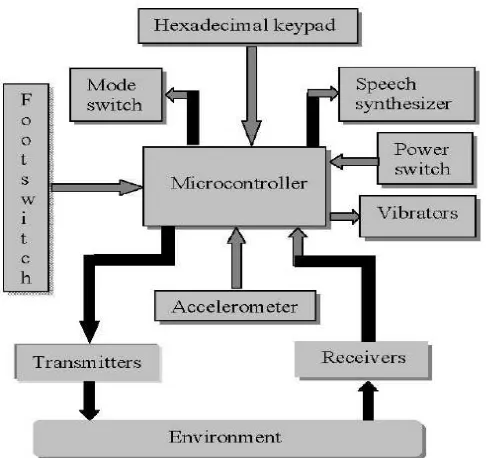
In this paper, an ultrasonic guidance system for blind people is developed without white cane by using microcontroller. This system consists of a microcontroller, an accelerometer, a footswitch, a speech synthesizer, a hexadecimal keypad, a mode switch, two ultrasonic sensors, two vibrators and a power switch. Figure 2.2 shows the block diagram of the system.
Figure 2.2: The Block Diagram Of The System
Basically this system has several functions. First of all is the obstacle detection function. This system detects the obstacle by using two ultrasonic sensors and gives direction instruction to the user by vibration. For example, if left ultrasonic sensor detects obstacle, then the left vibrator will vibrate. The vibration will increase if the distance between the user and the obstacle decrease and the vibration will decrease if the distance increases.
6 cross road, cross road junction, pedestrian crossing, steps, pause, and stop.
In the playback mode, there are forward and reverse directions. The aid measures again the distance travelled by the user. When this is equal to that stored in the memory for that particular section of the route, a corresponding decision word generated by the
synthesizer is given to the user. The audible signal indicates what action the user should take at this point, for instance turn left. In the reverse direction, the procedure is exactly the same except that the route information stored in the memory is used in reverse order, and that right and left are interchanged [4].
Figure 2.3: The Navigation Aid Worn By The Blind
This system is very user friendly as the system consists of multifunction. However, the placement of ultrasonic sensors at the shoulder of the user is too high will cause the ultrasonic sensors cannot detect the obstacle at lower level. If the user does not hold a white cane, this will very dangerous to the user.
2.3 A Low Cost Artificial Vision System for Visually Impaired People
7 system will be able to recognize objects using image processing algorithms. The system block diagram is shown in figure. From figure, we can see that the system consists of microcontroller, camera, ear speaker, ultrasonic sensors, EEPROM, digital to analog converter. The system can function in two modes, WALK mode and CAM mode. In WALK mode, the system uses ultrasonic sensors to detect obstacle and the voice command will guide the user to the right direction via ear speaker. In CAM mode, the vision camera is used to help the blind people in recognizing objects and text. Figure shows hardware setup of the system [5]. Figure 2.4 shows the system block diagram and Figure 2.5 shows the hardware setup of the system.
Figure 2.4 The System Block Diagram
8 This system can give the direction guidance accurately as the ultrasonic sensors are placed with angle so that the sensors can detect the obstacle from many directions,
including the dig. However, this system cannot determine the distance between the obstacle and user and give an instruction on it. Since this system did not involve white cane, this will very dangerous to the user.
2.5 Product Comparison
The table shows the distribution of particular design and proposed design. They will be compared in several criteria: accuracy, cost, user friendly, safety, and energy consumption. With this comparison, we can detect the strength and weakness of each product.
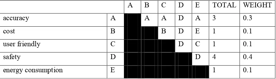
Table 2.1 Pair Wise Comparison Table of the Product’s Criteria
In the Table 2.1, we display all the important criteria which should be included in a product and weighted all of it. Next, we can arrange the importance of the particular criteria according it’s weight after compare with other entire criteria. From the Table 2.1, we found that safety (weight= 0.4) is the most important criteria to the product, follow by the accuracy (weight= 0.3). This means that we need to concentrate both of these criteria in the product designing.
A B C D E TOTAL WEIGHT
accuracy A A A D A 3 0.3
cost B B D E 1 0.1
user friendly C D C 1 0.1
safety D D 4 0.4
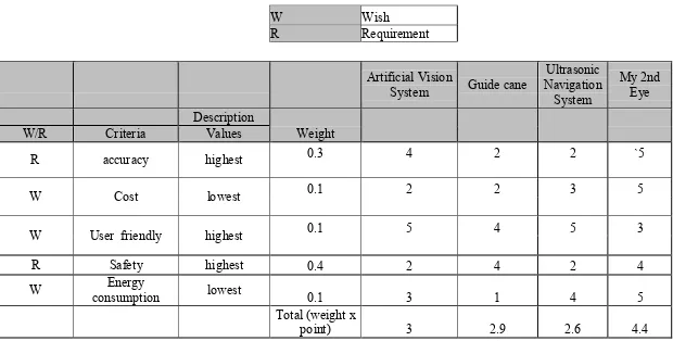
9 Table 2.2: Weighted Objective Table For The Products
W Wish
R Requirement
Artificial Vision
System Guide cane
Ultrasonic Navigation System My 2nd Eye Description Weight
W/R Criteria Values
R accuracy highest 0.3 4 2 2 `5
W Cost lowest 0.1 2 2 3 5
W User friendly highest 0.1 5 4 5 3
R Safety highest 0.4 2 4 2 4
W consumption Energy lowest 0.1 3 1 4 5
Total (weight x
point) 3 2.9 2.6 4.4
Table 2.3 Point Explanation
Very Low Low Moderate High Very High
11
2.6 Sensor Comparison
In this section, we will discuss the specification of 3 types of sensor: IR sensor, sonar sensor and laser sensor and compare their specification based on some criteria. Hence, we can choose the most suitable sensor for our system.
2.6.1 PING)))™ Ultrasonic Distance Sensor (#28015) (Ultrasonic sensor)
Figure 2.6: Ultrasonic Distance Sensor
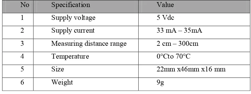
Ultrasonic sensor works by transmitting an ultrasonic (well above human hearing range) burst and providing an output pulse that corresponds to the time required for the burst echo to return to the sensor. By measuring the echo pulse width, the distance to target can easily be calculated. Table 2.4 display all the technical specification of the PING)))™ Ultrasonic Distance Sensor (#28015).
Table 2.4: Technical Specifications Of Ultrasonic Distance Sensor
[6]
No Specification Value
1 Supply voltage 5 Vdc
2 Supply current 33 mA – 35mA
3 Measuring distance range 2 cm – 300cm
4 Temperature 0°Cto 70°C
5 Size 22mm x46mm x16 mm