i
“ I hereby declare that I have read trough this report entitle “Design and evaluate the performance of Solar charging system for MY 2nd EYE project” and found that it has comply the partial fulfillment for awarding the degree of Bachelor of Electrical Engineering (Power Electronic and Drive)
Signature : ……….
Supervisor’s Name : Mr. ANUAR BIN MOHAMED KASSIM
ii
DESIGN AND EVALUATE THE PERFORMANCE OF SOLAR CHARGING SYSTEM FOR MY 2ND EYE PROJECT
ZULHAIMIE BIN BOLOH
A report submitted in partial fulfillment of the requirements for the degree of Bachelor Electrical Engineering
Faculty of Electrical Engineering
UNIVERSITI TEKNIKAL MALAYSIA MELAKA
iii
I declare that this report entitle “Design and evaluate the performance of Solar charging system for MY 2nd EYE project” is the result of my own research except as cited in the references. The report has not been accepted for any degree and is not concurrently submitted in candidature of any other degree.
Signature : ……….
Student Name : ZULHAIMIE BIN BOLOH
iv
Thanks to my beloved mother and father My Family
My supervisor
Mr. Anuar Bin Mohamed Kassim
v
ACKNOWLEDGEMENT
First of all, I would like to thank to Allah because I managed to complete the Final Year Project (FYP 2) report on time without face any difficult problem. The immense help and support received from many persons who generously advice and assist me while I was doing my FYP 1 which is compulsory to all Universiti Teknikal Malaysia Melaka (UTeM) students to pass before awarded.
I owe a debt of thanks to all those time, concern and efforts were given during the process of completing this report. Thus, our heartfelt gratitude is extended my beloved supervisor Mr. Anuar Bin Mohamed Kassim for giving the support morally and physically and shared his expertise and knowledge with me.
vi
ABSTRACT
vii
ABSTRAK
viii
LIST OF CONTENTS
CHAPTER PAGE
ACKNOWLEDGEMENT v
ABSTRACT vi
LIST OF CONTENTS viii
LIST OF TABLE xi
LIST OF FIGURES xii
LIST OF ABBREVIATION xiv
LIST OF SYMBOLS xv
LIST OF APPENDICES xvi
1 INTRODUCTION 1
1.1 Project Background 1
1.2 Problem Statement 1
1.3 Objective 2
1.4 Scopes 2
2 LITERATURE REVIEW 3
2.1 Introduction 3
2.2 Solar panel 3
2.3 Solar Charge Controller 4
2.4 Maximum Power Point Tracking (MPPT) 5
2.5 Summary of Literature Review 6
3 PROJECT BACKGROUND 7
3.1 Hardware 7
3.1.1 Solar Panel 7
3.1.2 Batteries 9
ix
3.1.4 SK40C 11
3.1.5 USB ICSP PIC Programmer V2010 11
3.2 Software 12
3.2.1 Solidworks 12
3.2.2 MikroC 13
3.2.3 Proteus 15
3.3 System Configuration 16
4 METHODOLOGY 19
4.1 Introduction 19
4.2 Project Methodology 19
4.3 Design Solar Charging System 20
4.3.1 Solar Charge Controller 21
4.4 Software Development 22
4.5 Circuit Simulation 24
4.6 Experiment Test 25
4.7 Program Solar Charge Controller 27
5 RESULTS AND DISCUSSION 31
5.1 Introduction 31
5.2 Solar Charge Controller of Buck Converter Circuit Simulation 31
5.3 Solar Charge Controller Analysis 33
5.4 Solar Charge Controller Operation 33
5.5 Experiment test result 35
5.5.1 Waveform from Solar Panel Terminal 35
5.5.2 Waveform from GET MOSFET Terminal 35
5.5.3 Waveform from Battery Terminal 36
5.6 Analysis Data during charging battery of the Solar Charge Controller 37
x
5.8 Data During Charging of the Solar Charge Controller 38
5.8.1 The Radiation from Sun 39
5.8.2 The Temperature From Weather 40
5.8.3 The photovoltaic voltage 40
5.8.4 The Photovoltaic Current 41
5.8.5 The Battery Capacity 42
5.8.6 The Battery Voltage 42
5.8.7 The Battery Current 43
5.9 Maximum Power Point Tracker (MPPT) Simulation 44
5.10 Analysis Actual Model ( PV, Boost Converter with MPPT ) 45
5.11 Analysis Actual Model ( PV, Boost Converter without MPPT ) 46
5.12 System Comparison 46
5.13 Discussion 47
6 CONCLUSION AND RECOMMENDATION 48
6.1 Conclusion 48
6.2 Recommendations 49
REFERENCES 50
APPENDIX A 52
xi
LIST OFTABLE
TABLE TITLE PAGE TABLE 3.1: The Specification of Solar Panel 12V 5W 8
TABLE 3.2: The specification of Energizer rechargeable battery 9
TABLE 3.3: The specification of Li-Po rechargeable battery 10
TABLE 4.1: The apparatus used in this experiment 22
TABLE 5.1: Analysis data during charging battery of the Solar Charge Controller 37
TABLE 5.2: Simulation result MPPT 44
TABLE 5.3: Result by using MPPT 45
xii
LIST OFFIGURES
FIGURE TITLE PAGE
FIGURE 2.1: Solar Powered Battery Charger 4
FIGURE 2.2: Solar Charge Controller 5
FIGURE 2.3: Charge controller set points 5
FIGURE 2.4: Charge controller using MPPT 6
FIGURE 2.5: Photovoltaic (PV) array V-I curve 6
FIGURE 3.1: Solar Panel 8
FIGURE 3.2: Type of batteries use in this project 9
FIGURE 3.3: SK40C 11
FIGURE 3.4: USB ICSP PIC Programmer V2010 11
FIGURE 3.5: Solidworks premium 2010 software cover 13
FIGURE 3.6: MikroC interface 14
FIGURE 3.7: Setting the new project 15
FIGURE 3.8: The interface of proteus 16
FIGURE 3.9: System configuration of sound warning system 17
FIGURE 3.10: System Configuration of Sound Warning System with Solar Charge Controller 15
FIGURE 4.1: Flowchart Project Methodology 20
FIGURE 4.2: Solar Charger Circuit with Voltage Regulator 21
FIGURE 4.3: Solar Charge Controller Circuit 22
FIGURE 4.4: Programming using MikroC 23
xiii FIGURE 4.6: The experiment for Solar Charge Controller and Photovoltaic at day light 26
FIGURE 4.7: The Experiment for Solar Charge Controller and Photovoltaic at night time 27
FIGURE 5.1: Proteus 7 Profeesional Schematic of Buck Converter 32
FIGURE 5.2: Waveform generated by Proteus 7 simulation of the Buck Converter circuit 32
FIGURE 5.3: Solar Charge Controller Analysis 33
FIGURE 5.4: Waveform from Solar Panel Terminal 35
FIGURE 5.5: Waveform from GET MOSFET Terminal 35
FIGURE 5.6: Waveform from battery terminal 36
FIGURE 5.7: Data during charging of the Solar Charge Controller 38
FIGURE 5.8: The Radiation from Sun 39
FIGURE 5.9: The temperature from weather 40
FIGURE 5.10: The photovoltaic voltage 40
FIGURE 5.11: The Photovoltaic Current 41
FIGURE 5.12: The Battery Capacity 42
FIGURE 5.13: The Battery Voltage 42
FIGURE 5.14: The Battery Current 43
xiv
LIST OF ABBREVIATION
AC Alternating Current
ARV Array Reconnect Voltage
C Programming language
DC Direct Current
CAD Computer Aided Design
DSP Digital Signal Processors
GPS Global Positioning System
FYP Final Year Project
I Current
IC Integrated Chip
LCD Liquid Crystal Display
LED Light Emitting Diode
MPPT Maximum Power Point Tracker
P Power
PIC A family of microcontroller
PV Photovoltaic
PWM Pulse Width Modulation
RPM Rapid Prototype Modeling
SBM Society of Blind Malaysia
SPV Solar Photovoltaic
USB Universal Serial Bus
UTeM Universiti Teknikal Malayisia Melaka
V Voltage
VR Voltage Regulation
xv
LIST OF SYMBOLS
R1 Resistor 1
R2 Resistor 2
Vin Voltage Input
V Voltage
I Current
R Resistor
P Power
D Duty Cycle
k kelvin
T Time
W/m2 Weber Per Square Meter
xvi
LIST OFAPPENDICES
APPENDIX TITLE PAGE
A Project 52
1
CHAPTER 1
1 INTRODUCTION
1.1 Project Background
The population of disable person is increased year by year and the 80 percent of disable person is located in developing countries. The number of disabled people in Malaysia is estimated about 2.8 million people from a population of Malaysian people. This number of population include the disable person that cannot be traced by government. This project is timed to develop the system to help the blind people move without any complication. This developing system uses the microcontroller to control the obstacle sensor and gives the input to the vibration motor as a warning system. This project can use battery and solar for energy supply in the circuit. Focus of this project is to make the user of this system can afford to buy this product and user friendly to the blind man. The user comfortability is our priority to this product because it involves the blind man that cannot see the world. Therefore, the involvement of the blind man to this project is important to make it successfully.
1.2 Problem Statement
A problem statement is a concise description of the issues that need to be addressed before solve the problem. We must come out with the solution to make sure our project successful.
2 The way to solve the problem is to make a device that is compact and user friendly, as well as to design.
1.3 Objective
The objectives of this project are:
1. To design the configuration of solar charging system.
2. To evaluate the performance for My 2nd eye project in order to ensure the device can be operated independently without what parameters.
1.4 Scopes
3
CHAPTER 2
2 LITERATURE REVIEW
2.1 Introduction
There are many products designed to help the disable person in order to improve the quality of life and they can live same as normal person. Especially to the visually impaired person that cannot see light of world. They cannot move with their own and must get help from the normal person to move anywhere. Many of them use the white cane to sense the obstacle around them. However, the white cane needs much training and also required help from others. This innovation is designed to help the blinds to move independently without any support from other people although in day light, because the device proposed will provide energy to the batteries in the form of solar energy from the sun.
2.2 Solar panel
The Solar panel is a power transfer photo electricity component. It transfers sunlight energy to electric energy. Therefore, photo electricity component is called Solar cell. From physics point of view, solar panel is also called Photovoltaic (PV), which means that photo is light and voltaic is electrics [1].
4 such a system are the simplicity and low cost. The disadvantages are the PV panel can only provide charging current when its output voltage is higher than the battery voltage and the system does not always work at the optimal to convert the available solar power into electricity. A controller can be added between PV panel and the battery for improvement of the system performanceas shown in Figure 2.1(b) [2].
(a) with diode
(b) with optimal controller
Figure 2.1: Solar Powered Battery Charger [2].
2.3 Solar Charge Controller
5
Figure 2.2: Solar Charge Controller.
Figure 2.2 show about charge controller set points. There are many differences between charging and discharging. Voltage regulation show maximum situation when charging and low voltage load disconnect when discharging [3].
Figure 2.3: Charge Controller set points [3].
2.4 Maximum Power Point Tracking (MPPT)
6
Figure 2.4: Charge controller using MPPT
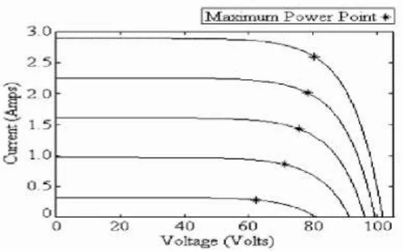
Figure 2.5: Photovoltaic (PV) array V-I curve [4].
2.5 Summary of Literature Review
The fields of literature review for this project are studied so far, includes are solar charging system, Solar Charge Controller and Maximum Power Point Tracker (MPPT). Solar Photovoltaic (SPV) technique is the most popular way of utilizing solar energy storage to supply the load power when solar power is not available. The power voltage characteristics of the Photovoltaic (PV) module varies depending upon atmospheric conditions and has unique peak on it.
7
CHAPTER 3
3 PROJECT BACKGROUND
This project can be divided into two major parts which are software part and hardware part. The software part involves the development of the program for microcontroller to integrate the input with warning system, to perform the simulation and to set the frequency sound. While, the hardware part includes the design and development of the warning system, design of the controller and location of the speaker. Next, the hardware part includes the design and development solar charging for My 2nd Eye project. The system of this project also will be discussed in this chapter.
3.1 Hardware
The hardware for this project can be divided into mechanical parts, electrical and electronics parts. The mechanical parts consist of the solar panel, rechargeable battery and Distribution Board (DB). The electrical and electronics parts consists of microcontroller circuit, solar charge controller circuit, the components electronics such as capacitor, resistor, integrated chip (IC), voltage regulator, wires and connectors.
3.1.1 Solar Panel
8 or thin-film cells based on cadmium or silicon. The conducting wires that take the current off the panels may contain silver, copper or other non-magnetic conductive transition.
Figure 3.1: Solar Panel.
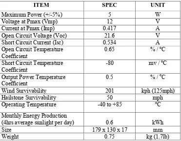
Table 3.1: The specification of Solar Panel 12V 5W
ITEM SPEC UNIT
Maximum Power (+/-5%) 5 W
Voltage at Pmax (Vmp) 12 V
Current at Pmax (Imp) 0.417 A
Open Circuit Voltage (Voc) 21.6 V
Short Circuit Current (Isc) 0.534 A
Open Circuit Temperature
Coefficient 0.65 % /
oC
Short Circuit Temperature
Coefficient -80 mv /
oC
Output Power Temperature
Coefficient 0.5 % /
oC
Wind Survivability 201 kph (125mph)
Hailstone Survivability 50 mph
Operating Temperature -40 to +85 oC
Monthly Energy Production
(4hrs average sunlight per day) 0.6 kWh
Size 179 x 130 x 17 mm
Weight 0.75 kg (1.7lb)
![Figure 2.3: Charge Controller set points [3].](https://thumb-ap.123doks.com/thumbv2/123dok/576051.68313/21.595.162.470.328.519/figure-charge-controller-set-points.webp)