DESIGNING 2.45GHZ RECTENNA FOR LOW VOLTAGE APPLICATION
NUR HIDAYAH BINTI MAHMUD
This Report Is Submitted in Partial Fulfillment of Requirements for the Bachelor Degree of Electronic Engineering (Wireless Communication)
Faculty of Electronic and Computer Engineering Universiti Teknikal Malaysia Melaka
UNIVERSITI TEKNIKAL MALAYSIA MELAKA
FAKULTI KEJURUTERAAN ELEKTRONIK DAN KEJURUTERAAN KOMPUTER
BORANG PENGESAHAN STATUS LAPORAN PROJEK SARJANA MUDA II
Tajuk Projek : DESIGNING 2.45GHZ RECTENNA FOR LOW VOLTAGE APPLICATION
Sesi
Pengajian : 1 2 / 1 3
Saya NUR HIDAYAH BINTI MAHMUD
mengaku membenarkan Laporan Projek Sarjana Muda ini disimpan di Perpustakaan dengan syarat-syarat kegunaan seperti berikut:
1. Laporan adalah hakmilik Universiti Teknikal Malaysia Melaka.
2. Perpustakaan dibenarkan membuat salinan untuk tujuan pengajian sahaja.
3. Perpustakaan dibenarkan membuat salinan laporan ini sebagai bahan pertukaran antara institusi
pengajian tinggi.
4. Sila tandakan ( √ ) :
SULIT*
*(Mengandungi maklumat yang berdarjah keselamatan atau kepentingan Malaysia seperti yang termaktub di dalam AKTA RAHSIA RASMI 1972)
TERHAD** **(Mengandungi maklumat terhad yang telah ditentukan oleh
organisasi/badan di mana penyelidikan dijalankan)
TIDAK TERHAD
Disahkan oleh:
__________________________ ___________________________________
(TANDATANGAN PENULIS) (COP DAN TANDATANGAN PENYELIA)
iii
“I hereby declare that this report is the result of my own work except for quotes as
cited in the reference”
Signature :
iv
“I hereby declare that I have read this report and in my opinion this report is
Sufficient in terms of the scope and quality for the award of Bachelor of Electronic Engineering (Wireless Communication) With Honours”
Signature :
Supervisor’s Name: ENGR. NAJMIAH RADIAH BINTI MOHAMAD
v
vi
ACKNOWLEDGEMENT
I am grateful to the Almighty with His grace and guidance that I was able to complete this thesis.
I take this opportunity to express my profound gratitude and deep regards to my guide (Engr. Najmiah Radiah Binti Mohamad) for her exemplary guidance, monitoring and constant encouragement throughout the course of this project. The blessing, help and guidance given by her time to time shall carry me a long way in the journey of life on which I am about to embark.
I would like to thank everyone who involved directly and directly in this project. The sacrifice and commitment given towards me earning my bachelor’s degree are indescribable and without them, this thesis would not be completed.
vii
ABSTRACT
This project is another method to harvest energy compared to solar ener gy because solar energy because solar energy have some limitation. In space, even the satellite has a solar panel to generate energy, radio frequency also can be generated using as a backup power. The main objective of this project is to design a rectenna which operates at 2.45 GHz, frequency centered at ISM band that can capture the microwave signal or RF signal and convert it into DC power. Besides that, the other objective is to fabricate the rectenna for wireless transmission and applied it in low voltage application. In order to achieve these objectives, a patch antenna and rectifying circuit had been designed separately using CST Microwave Studio and then will be fabricated on FR4 board. The impedance matching for both designs are set at 50 ohms. Two Shcottky diodes (HSMS 2860) are used in the rectifying circuit that provide full wave configuration to generate DC voltage. Measurement experiment had been done by using several antennas as the transmitter and rectenna as the receiver to measure output voltage at different power transmit and load. Based on the experimental result, the maximum output voltage produce at the receiver is
2.112V for load 820kΩ and input power, 20dBm by horn antenna. This rectenna can
viii
ABSTRAK
Projek ini adalah satu lagi kaedah untuk menuai tenaga berbanding dengan tenaga solar kerana tenaga solar mempunyai beberapa batasan. Di udara, walaupun satelit mempunyai panel solar untuk menjana tenaga, frekuensi radio juga boleh dihasilkan untuk digunakan sebagai kuasa sandaran. Objektif utama projek ini adalah untuk mereka bentuk rectenna yang beroperasi pada 2.45GHz,frekuensi tengah ISM band yang boleh menangkap isyarat gelombang mikro atau is yarat RF dan menukarkan ia menjadi kuasa DC. Selain itu, objektif lain adalah untuk mereka rectenna untuk penghantaran tanpa wayar dan digunakan dalam aplikasi voltan rendah. Dalam usaha untuk mencapai objektif ini, antena dan litar penerus telah direka secara berasingan menggunakan CST Microwave Studio dan kemudian dicetak pada papan FR4. Padanan impedans bagi kedua-dua reka bentuk telah ditetapkan kepada 50 ohm. Dua Shcottky diod(HSMS 2860) digunakan pada pada litar penerus yang menyediakan konfigurasi ge lombang penuh untuk menjana voltan DC. Eksperimen telah dilakukan dengan menggunakan beberapa antenna sebagai penghantar dan rectenna sebagai penerima untuk mengukur voltan keluaran pada kuasa dan beban yang berbeza. Berdasarkan keputusan eksperimen, volta n keluaran
maksimum yang dihasilkan pada penerima adalah 2.112V untuk 820KΩ beban dan
ix
TABLE OF CONTENT
CHAPTER CONTENTS PAGE
PROJECT TITLE i
REPORT STATUS VERIFICATION ii
STUDENT’S DECLARATION iii
SUPERVISIOR DECLARATION iv
DEDICATION v
ACKNOWLEDGEMENT vi
ABSTRACT vii
ABSTRAK viii
CONTENT ix
LIST OF FIGURES xiii
LIST OF TABLES xvi
LIST OF ABBREVAIATION xvii
I INTRODUCTION 1
1.1 Introduction on a Rectenna 1
1.2 Objectives 2
1.3 Problems Statement 3
1.4 Project Scope 3
1.5 Methodology 4
x
II LITERATURE REVIEW 7
2.1 Overview of Microwave Wireless Power
Transmission 7
2.2 History of Wireless Power Transmission 8
2.3 The Rectenna 10
III THEORETICAL BACKGROUND 12
3.1 ISM Band 12
3.2 Radio Frequency Identification 13
3.3 Microstrip Antenna 13
3.4 Horn Antenna 15
3.5 Antenna Parameters 16
3.31 Directivity 16
3.32 Gain 17
3.33 Input Impedance 17
3.34 Antenna Efficiency 18
3.35 Beamwidth 19
3.6 Circular Polarization 20
IV METHODOLOGY 21
4.1 Software 21
4.2 Materials 22
4.2.1 Photoresist Board 22
4.2.2 Schottky Diode 23
4.2.3 SMA Connector 24
4.2.4 SMA Adapter 24
xi
4.3 Equipment 25
4.3.1 Network Analyzer 25
4.32 Signal Generator 25
4.33 RF Cable 26
4.34 Horn Antenna 26
4.35 Digit Multimeter 27
4.4 Procedure Of Project 27
4.4.1 Antenna Design Procedure 27
4.4.2 Rectifier Design Procedure 30
4.4.3 Etching Process 31
4.4.4 Experiment Setup 33
4.4.5 Measurement Procedure 33
4.5 Overall Budgets 35
V RESULT AND DISCUSSION 36
5.1 Antenna Design 36
5.1.1 Characteristic of Antenna (Return Loss) 39
5.1.2 Bandwidth 41
5.1.3 Surface Current 41
5.1.4 Directivity and Gain 42
5.1.5 Impedance Matching 43
5.1.6 Radiation Pattern 44
5.2 Rectifier Design 50
5.3 Rectenna Measurement Results 51
5.3.1 Output Voltage Versus Power Transmit 51
xii
VI CONCLUSION AND RECOMMENDATION 56
6.1 Conclusion 56
6.2 Recommendation 57
REFERENCES 58
xiii
LIST OF FIGURES
Figure Titles Pages
1.1 Block diagram of rectenna design 4
1.2 Flow Chart for the Rectenna Project 5
2.1 WPT for UAV Applications 8
2.2 Nikola Tesla in his Colorado Springs Laboratory which was 9 Constructed to experiment with radio waves for power
transmission
3.1 Basic Principle of Microwave RFID Systems 13
3.2 Microstrip Layout Structure 14
3.3 Representative shapes of Microstrip patch elements 14
3.4 Horn Antenna 15
3.5 Thevenin equivalent of an Antenna 17
3.6 Antenna reference terminals 18
3.7 Reflections, conduction and dielectric losses 18 3.8 Two dimensional represantation of Beamwidth 20
3.9 Circular Polarization Wave 20
4.1 CST microwave studio software 22
4.2 Photoresist board 22
4.3 Top View of HSMS 2860 23
4.4 SMA connecter 24
4.5 SMA adapter 24
4.6 Resistor 25
4.7 Network Analyzer 25
4.8 Signal Generator 26
4.9 RF Cable 26
xiv
4.10 Digit Multimeter 27
4.12 Substrate Design 28
4.13 Ground Design 28
4.14 Patch Design 29
4.15 Waveguide Port Design 29
4.16 Transient Solver Parameters 29
4.17 Dimension of Antenna 30
4.18 Dimension of Rectifying Circuit 30
4.19 Printed Antenna Layout 31
4.20 Printed Rectifier Layout 31
4.21 Circuit Developer Chemical 32
4.22 Etching Machine 32
4.23 Drying Process 32
4.24 Rectenna Measurement Setup 33
4.25 Distance of the Rectenna and Horn Antenna 34
4.26 Measurement of Rectifying Circuit 34
5.1 Basic layers of microstrip antenna 37
5.2 Layout of Antenna 38
5.3 Structure of antenna 38
5.4 Parametric Study of Length Patch Antenna 39
5.5 Parametric Study of Width Patch Antenna 39
5.6 Resonant Frequency and Return Loss 40
5.7 Bandwidth 41
5.8 Surface Current 42
5.9 Gain and Directivity of Antenna 43
5.10 S-Parameter Smith Chart 43
5.11 Polar View Radiation Pattern of Antenna 44
xv
5.18 Position Polar Horn Antenna x E plane Patch Antenna 47 5.19 Radiation Pattern of Polar Horn Antenna x E plane Patch Antenna 48
5.20 Radiation Pattern of Yagi Ex Patch E 48
5.21 Radiation Pattern of Yagi E x Patch H 49
5.22 Radiation Pattern of Yagi H x Patch E 49
5.23 Radiation Pattern of Yagi H x Patch H 49
5.24 Rectifying Circuit 50
5.25 Output Voltage Rectifying Circuit 50
5.26 Graph Output Voltage Versus Power Transmit At A Distance
20cm 51
5.27 Graph Output Voltage Versus Power Transmit At A Distance
40cm 52
5.27 Graph Output Voltage Versus Power Transmit At A Distance
60cm 53
5.28 Graph Output Voltage Versus Power Transmit By Varying
Distances 53
xvi
LIST OF TABLES
Table Titles Pages
3.1 Frequency Range, Bandwidth and Center Frequency in ISM Band 12
4.1 FR4 Board Parameter 23
4.2 Overall Budgets For This Project 35
xvii
LIST OF ABBREVIATIONS
AC -Alternating Current
DC -Direct Current
FR4 -Flame Retardant 4
RF -Radio Frequency
RECTENNA -Rectifying Antenna
ISM - Industrial, Scientific and Medical
RFID - Radio Frequency Identification
LED -Light Emitting Diode
MPT -Microwave Power Transmission
HF -High Frequency
SMA -Sub Miniature Version A
UV -Ultra Violet
WPT - Wireless Power Transmission
HPBW -Half Power Beamwidth
FNBW -First Null Beamwidth
CP -Circular Polarization
UHF - Ultra High Frequency
1
CHAPTER I
INTRODUCTION
This chapter will give an overview about the project as project background, project objective, project scope, project methodology and summary of the project. This chapter will also explain briefly the overall project progress from beginning until the project is complete.
1.1 Introduction on a Rectenna
2
The rectenna (rectifying antenna) is an important device for converting microwave signal into useful DC power. A rectenna contains an antenna as the receiver which collects microwave signal and a rectifying circuit to convert RF power into DC power.
A rectifying circuit is often made up of a combination of Schottky diodes, an input HF filter, an output bypass capacitor and a load resistor. The input HF filter, localized between the antenna and diodes, is a low-pass filter which rejects harmonics created by the nonlinear diode behavior. It also acts as a matching circuit between the antenna and the rectifier.
The modeling of individual elements such as patch antenna, diode and low pass filter gives us better insight towards the optimization of parameters for enhanced efficiency of rectenna [3]. But, usually microstrip line technology is used to develop rectenna circuits. In this approach, filter components are made by varying geometric parameters of connected lines. This method constrains us to use electromagnetic simulations coupled with circuit simulations to design the rectenna circuit.
1.2 Objectives
The objectives of this project are to design and testing a rectenna which operates at 2.45GHz, frequency centered at ISM that can capture the microwave signal or RF signal surrounding us and convert into DC power. Besides, the other objective is to fabricate the rectenna for wireless transmission and applied it in low
voltage application. In today’s fast paced world, this project will give more benefit to
3
1.3 Problems Statement
This project is undertaken as a solution for how to generate the power without using either electricity or solar because in some places, this two power source is not available due to some circumstance. For example in space, even the satellite has a solar panel to generate energy, they also can use a microwave or radio frequency to generate energy as a backup power. Besides, ambient frequency which is wasted surround us can be converted into DC voltage. Another problem is regarding the lifetime of the batteries which is very limited even for low power batteries, requiring impractical periodical battery replacement.
Furthermore, there are some problems reported regarding the designing a rectenna and overcome due to the problem. Based on the International Journal of Engineering Science and Technology, R. K. Yadav et al reported that in general it is difficult to predict how the rectenna system is optimized for the maximum conversion efficiency [4].Besides, J. A. G Akkermans reported that using rectenna, the amounts of power that can be transferred are limited due free space path loss [5].
.
1.4 Project Scope
4
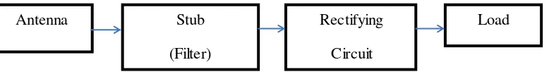
Figure 1.1: Block diagram of rectenna design
1.5 Methodology
The project is started on designing a printed antenna that can operate on 2.45GHz by using CST Microwave Studio. The antenna is design separately from the rectifying circuit. The proposed antenna design is designing with truncated edges to generate circularly polarized which is attractive for wireless transmission to maximize the output of the conversion.
Then, the rectifier which is matched with the impedance of the antenna is designed. There are two methods of designing the rectifier which is a half wave rectifier with single diode configuration and full wave rectifier with dual diode configuration. Full wave rectifier was selected for this project because it can provide twice higher DC output compared to half wave rectifier. To suppress re-radiation and to maximize the power conversion, low pass filter (or band pass filter) is placed between the antenna and rectifier setup. The cutoff frequency for low pass filter has been selected such that second harmonic signals are rejected. Numerous types of filters have been reported for rectenna second harmonic rejection [6] [7].Rectifier should be designed with zero biased Schottky diode [8]. The selected diode should be able to rectify at very low input power, typically -10 dBm to 0 dBm.
The filter designed is a band pass filter that passes the frequency 2.45GHz and with low insertion loss. Besides, this filter design can block higher order harmonic frequency. To avoid unwanted power dissipation, the harmonics generated by the diode need extra attention. To avoid dissipation of the harmonics in the load, a radial stub that is placed between the Schottky diode.
Antenna Stub
(Filter)
Rectifying
Circuit
[image:21.596.120.509.87.138.2]5
Then, the matching circuit between the antenna and rectifying is done. The impedance antenna and the rectifying circuit must be matched because the output of the antenna will be the input for rectifying circuit. The impedance matching stage is essential in providing maximum power transfer from the antenna to the rectifying circuit.
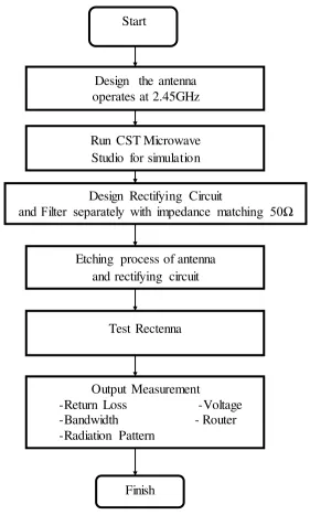
Figure 1.2 : Flow Chart for the Rectenna Project Etching process of antenna
and rectifying circuit
Test Rectenna
Output Measurement
-Return Loss -Voltage -Bandwidth - Router -Radiation Pattern
Finish Start
Design the antenna operates at 2.45GHz
Run CST Microwave Studio for simulation Design Rectifying Circuit
[image:22.596.176.457.169.636.2]6
1.6 Thesis Outline
This report consists of six (6) chapters which are will explain detail about the project of designing a 2.45GHz rectenna for wireless energy harvesting.
The first chapter in this report is about the introduction of rectenna. This chapter will give an overview about the project as background, project objective, project scope, project methodology and summary of the project. This chapter will explain briefly about the overall project progress from the beginning until the project is complete.
The second chapter is a literature review. This chapter delved into the history of RF and discussed the pioneering effort of the early scientists who showed and confirmed the presence of RF within the electromagnetic spectrum. The developments that have taken place and the improvements since the Second World War are also highlighted.
The third chapter is theoretical background. This chapter will review the equipment and devices used to complete the experiments. The best techniques and materials will be chosen to implement in this project.
The fourth chapter is a methodology where it is described the methods and techniques that have been used in this project. This chapter will give detailed information about the materials, equipment, and experimental procedures that have been used in this project.
The fifth chapter will present in the results of the project and conditions that were met from the implementation and realization of the rectenna system for low voltage application.
7
CHAPTER II
LITERATURE REVIEW
This chapter will discuss about the fact and information about microwave wireless power transmission and current study of finding of rectenna.
2.1 Overview of Microwave Wireless Power Transmission
The concept of Wireless Power Transmission (WPT) is to transmit DC power from one point to another through the atmosphere without the physical need of transmission lines. WPT could be realized by microwave or electromagnetic. This process usually involves direct current (DC) to alternating current (AC) power conversion. Besides, this process followed by the transmission of electromagnetic wave through radiation from the antenna. The electromagnetic wave is collected and converted into DC to power load for receiving part. The load is either a resistor or low voltage devices.