PIC BASED ANTI-TIE DOWN MODULE
MOHD HAFIS BIN HASSAN
This report is submitted in partial fulfillment of the requirement for the award of Bachelor of Electronic Engineering (Industrial Electronics) With Honours
Faculty of Electronic and Computer Engineering Universiti Teknikal Malaysia, Melaka
UNIVERSTI TEKNIKAL MALAYSIA MELAKA
FAKULTI KEJURUTERAAN ELEKTRONIK DAN KEJURUTERAAN KOMPUTER
BORANG PENGESAHAN STATUS LAPORAN PROJEK SARJANA MUDA II
Tajuk Projek : PIC BASED ANTI-TIE DOWN MODULE
……… Sesi
Pengajian : 0 9 / 1 0
Saya MOHD HAFIS BIN HASSAN
……….. (HURUF BESAR)
mengaku membenarkan Laporan Projek Sarjana Muda ini disimpan di Perpustakaan dengan syarat-syarat kegunaan seperti berikut:
1. Laporan adalah hakmilik Universiti Teknikal Malaysia Melaka.
2. Perpustakaan dibenarkan membuat salinan untuk tujuan pengajian sahaja.
3. Perpustakaan dibenarkan membuat salinan laporan ini sebagai bahan pertukaran antara institusi
pengajian tinggi.
4. Sila tandakan ( √ ) :
SULIT*
*(Mengandungi maklumat yang berdarjah keselamatan atau kepentingan Malaysia seperti yang termaktub di dalam AKTA RAHSIA RASMI 1972)
TERHAD** **(Mengandungi maklumat terhad yang telah ditentukan oleh organisasi/badan di mana penyelidikan dijalankan)
TIDAK TERHAD
Disahkan oleh:
__________________________ ___________________________________ (TANDATANGAN PENULIS) (COP DAN TANDATANGAN PENYELIA)
Alamat: 499, Jalan Arkid 2 Taman Arkid, 08000, Sg Petani, Kedah.
iii
“I hereby declare that this report is the result of my own work and research except for quotes and cited in the references.”
Signature :………...
iv
“I hereby declare that I have read this report and in my opinion this report is sufficient in terms of the scope and quality for award of Bachelor of Electronic
Engineering (Industrial Electronic) With Honours.”
Signature :………...
Supervisor’s Name : EN. AHMAD NIZAM BIN MOHD JAHARI @ JOHARI
v
vi
ACKNOWLEDGEMENT
Assalammualaikum W.B.T…
First of all I would like to thank ALLAH S.W.T because for HIS blessing, I have completed my final year project for courses Bachelor of Electronic Engineering (Industrial Electronics) successfully.
I would like to extend my deepest gratitude to my supervisors, EN. AHMAD NIZAM B. MOHD JAHARI @ JOHARI for her consistent supervision, guidance, support, and encouragement throughout this project.
I also want to thanks to my beloved family for their patience and understanding throughout my studies in Universiti Teknikal Malaysia Melaka (UTeM).
vii
ABSTRACT
viii
ABSTRAK
ix
TABLES OF CONTENT
CHAPTER TITLE PAGE
PROJECT TITLE i
DECLARATION iii
APPROVAL iv
DEDICATION v
ACKNOWLEDGEMENT vi
ABSTRACT vii
ABSTRAK viii
TABLE OF CONTENT ix
LIST OF TABLES xii
LIST OF FIGURES xiii
LIST OF APPENDICES xv
I INTRODUCTION 1
1.1 Project Introduction 1
1.2 Objective 2
1.3 Problem Statement 2
1.4 Scope 2
1.5 Research Methodology 3
x
II LITERATURE REVIEW OF PROJECT 5
2.1 Industrial Accident 5
2.1.1 Definition of Industrial Accident 5
2.1.2 Accident Causation Models 6
2.1.3 Causes of Accident 6
2.2 Anti-tie Down System 8
2.2.1 Anti-tie Down Logic Using PLC 8
2.3 Overview of Major Components Involved 9
2.3.1 Infrared Proximity Sensor 9
2.3.1.1 Reflected IR Sensor Strength 10
2.3.1.2 Modulated IR Signal 10
2.3.1.3 Circuit of Proximity Sensor 10
2.3.2 Microcontrollers PIC 16F877A 13
III RESEARCH METHODOLOGY 14
3.1 Design Constrains & Solutions 14
3.2 Phases of Method 15
3.3 The Flow Chart 17
3.4 Hardware Development 19
3.5 Microcontroller 19
3.5.1 Pin Diagram of PIC16F877A 20
3.5.2 PIC16F877A Port Assignment 21
3.5.3 Block Diagram of PIC16F877A 23
3.5.4 Basic Circuit for a Microcontroller 23
3.6 Printed Circuit Board (PCB) 25
3.6.1 PCB Design Rule and Consideration 25
3.7 Software Development 26
3.7.1 C Language 26
xi
IV ANALYSIS, TESTING AND RESULT 29
4.1 Result 29
4.1.1 Process 30
4.1.2 Basic Operational 30
4.1.3 Circuit 31
4.2 Analysis 33
4.2.1 Software Analysis 33
4.2.2 Hardware Analysis 35
4.2.2.1 Hardware Testing at Breadboard 36 4.2.2.2 Hardware Analysis for Finish Product 38
V DISCUSSION AND CONCLUSION 42
5.1 Discussion 42
5.2 Conclusion 43
5.3 Project Improvement and Suggestion 43
REFERENCES 44
APPENDICES 45
Appendix A 45
xii
LIST OF TABLES
NO TITLE PAGE
2.1 The Advantages of PIC than PLC 9
2.2 Comparison of the Sensor 13
3.1 Design Constrains Versus Alternative Solutions 15
3.2 PIC pin number that used in Anti-tie down Module 21
3.3 Common Design Rules of PCB Layout Design 26
xiii
LIST OF FIGURES
NO TITLE PAGE
1.1 Block diagram of the Anti-tie down module System 3
2.1 IR Sensor Circuit 11
2.2. Result of A/D Conversion in Two A/D Registers 11
2.3 The ADCON1 Register 12
2.4 The AD Port Configuration Bits 12
3.1 Waterfall Model for Anti-tie Down Module 16
3.2 Flow Chart of PSM1 17
3.3 Flow Chart of PSM2 18
3.4 Hardware Block Diagram 19
3.5 Pin Diagram of Microcontroller PIC16F877A 20
3.6 Block Diagram of Microcontroller PIC16F877A 23
3.7 Basic Circuit for a Microcontroller 24
4.1 Block Diagram of Anti-tie Down Module 30
4.2 Operation of Anti-tie Down Module 31
4.3 Voltage Regulator Circuit 32
4.4 Basic IR Sensor Circuit 32
4.5 Anti-tie Down module circuit design using ISIS Proteus 7.1. 34 4.6 The output will active if the both of input switch are active until 5 second 34
4.7 Anti-tie Down Module Layer PCB Layout 35
4.8 Finish Product 36
4.9 The Fault Condition 37
xiv
4.13 The Input Voltage for Input Switch2 not active – 0V 40 4.14 The Input Voltage for Input Switch2 active – 2.53V 40
xv
LIST OF APPENDICES
NO TITLE PAGE
A Ldmicro Software 45
CHAPTER I
INTRODUCTION
1.1 Project Introduction
Anti-tie down module is normally designed by using PLC logic in a semi-automatic machine. Using anti-tie down insures safety by making sure the user hands are in a safe position during a potentially hazardous motion. The PLC designs has a several disadvantages such as too much work required in connecting wires, difficulty in component changes or replacements, difficulty in finding errors; requiring skillful work force and when the problem occurs, hold-up time is indefinite, usually long.
This idea of PLC logic in anti-tie down system will upgrade to PIC system. The anti-tie down module system is control by using programmable microcontroller (PIC). The circuit using PIC will make the hardware circuitry compact and easy with change or replacement the components.
2
1.2 Objective
The objective of this project is to design and build a system to insure safety for worker during conducts a machine at working area and design and build a prototype of anti-tie down module using PIC microcontroller to make the hardware circuitry compact and easy with changes or replacement the components and also user frendly.
1.3 Problem Statement
In industrial, there are a lot of hazardous machine that have high dangerous risk to the worker. Using anti-tie down system insures safety to the operator, especially their hands in a safe position during a potentially hazardous motion.
1.4 Scope
Firstly, do some researches about a anti-tie down system. For the simulation part:
a) Anti-tie down module is target to be operated by using Microchip PIC as a microcontroller implement the input function into the closed loop system. b) Simple switches are use as an input.
c) The output will be connect to a simple machine module.
d) Using software to produce .hex file for interface to the hardware.
For the Hardware Part:
a) Finding and design the desired circuit.
3
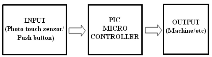
[image:18.595.140.502.158.255.2]After finish build up the hardware, testing and troubleshooting should be done to check wheter the hardware is in good condition.
Figure 1.1: Block diagram of the Anti-tie down module System
1.5 Research Methodology
There are 4 phases of methodology in order to achieve the objective of the project. The first phase is project planning, second phase is literature review, third stage hardware design and final phase is performance test.
1.6 Report Structure
These reports obtain five chapters that explain details about this project. The first chapter is introduction of the project. This chapter contains project introduction, project objective, project scope, problem statement and research methodology.
4
The third chapter is Research Methodology. This chapter will decide the selecting from literature review of figure out a few technique and approach that been conducted. This is to make sure that all data and other technique will involve. The factor, procedures, devices and method used to generate the expected results will include in this chapter. This chapter also gives information about a circuit and the main components used. The components are PIC (microcontroller).
The fourth chapter is focused on to build a few programming during attend the PIC class and laboratory. The purpose of the test, expected result, procedures and result for each test will be detailed out in this report (PSM 2).
CHAPTER II
LITERATURE REVIEW OF PROJECT
This chapter will discuss precisely about the project, which includes the Anti-tie down system, overview of the major component involved and overview of the project. This chapter also will discuss about industrial accident, accident cause and safety system.
2.1 Industrial Accident
2.1.1 Definition of Industrial Accident
6
2.1.2 Accident Causation Models
Accident causation model is not a new model to identify the root problem of safety in construction and other industry. The objective of this model is to provide tools for better industrial accident prevention program (Abdelhamid and Everett, 2000). As described by Heinrich (1980) accident prevention is an integral program, a series of coordinate activities, directed to the control of unsafe personal performance and unsafe mechanical conditions, and based on certain knowledge, attitudes, and abilities. The famous models that were developed that relate to accident causation are namely domino theory that was invented by Heinrich in 1930 and multiple causation theory that was developed by Petersen in 1971.
2.1.3 Causes of Accident
Accident don’t just happen, they are caused. According to Ridley 99 percent of the accident are caused by either unsafe acts or unsafe conditions or both (Ridley, 1986). As such, accidents could be prevented. The unsafe act is a violation of an accepted safe procedure which could permit the occurrence of an accident. The unsafe condition is a hazardous physical condition or circumstances which could directly permit the occurrence of an accident. Most accident results from a combination of contributing causes and one or more unsafe acts and unsafe condition. Accident theories have evolved from merely blaming workers, conditions, machineries into management roles and responsibilities. Nowadays, accident models are being used to better explain the causes of accident so that appropriate actions could be taken to make improvement. However, in order to effect permanent improvement, we must deal with the root causes of accident.
7
a more comprehensive study in the USA and classified the causes into human and physical factors. Human factors were due failed to secure and warn; Failed to wear personal protective equipment (PPE); horseplay; operating equipment without authority; operating at unsafe speed; personal factor; remove safety device; serviced moving and energized equipment; took unsafe position or posture; used defective tool or equipment; and other unsafe action. While, physical factors were due to; unsafe act of another person(s); disregard known prescribed procedures; defects of accident source; dress or apparel hazard; environmental hazard; fire hazard; hazardous arrangement; hazardous method; housekeeping hazard; improper assignment of personnel; inadequately guarded; public hazard; and other unsafe conditions.
Lubega et al (2000) did a study in Uganda and concluded the causes of accidents were mainly due to lack of awareness of safety regulations; lack of enforcement of safety regulations; poor regard for safety by people involved in construction projects; engaging incompetent personnel; non-vibrant professionalism; mechanical failure of construction machinery/equipment; physical and emotional stress; and chemical impairment. Pipitsupaphol and Watanabe (2000) did a study in Thailand construction sites and classified the causes into the most influential factors i.e. unique nature of the industry; job site conditions; unsafe equipment; unsafe methods; human elements; and management factors. They further concluded that major immediate causes were due to failure to use personal protective equipment; improper loading or placement of equipment or supplies; failure to warn co-workers or to secure equipment; and improper use of equipment.
8
regulation; lack of organizational commitment; low education level of workers; poor safety conscientiousness of workers; lack of personal protective equipment (PPE); ineffective operation of safety regulation; lack of technical guidance; lack of strict operational procedures; lack of experienced project managers; shortfall of safety regulations; lack of protection in material transportation; lack of protection in material storage; lack of teamwork spirits; excessive overtime work for labor; shortage of safety management manual; lack of innovative technology; and poor information flow.
2.2 Anti-Tie Down System
Anti-tie down module is a safety system product normally used in a semi-automatic machine. Using anti-tie down insures safety by making sure the user hands are in a safe position during a potentially hazardous motion. [2].
2.2.1 Anti-tie Down Logic using PLC
Anti-tie down module is a normally a design using PLC logic in a semi-automatic machine. However, The PLC designs have a several disadvantages like too much work required in connecting wires, difficulty with changes or replacements, difficulty in finding errors; requiring skillful work force and when a problem occurs, hold-up time is indefinite, usually long.
9
[image:24.595.106.534.256.535.2]Operators' placing their hands on the push buttons at the same time is a safety issue. If a false input on one of the buttons were sensed, then it would only take the other input to start the machine cycle. Some past causes of the false input conditions could be a person laying a rag on top of one of the buttons. However these types of false input considerations must be taking into account so your logic can be written to prevent false cycle starts and possibility prevent bodily harm.
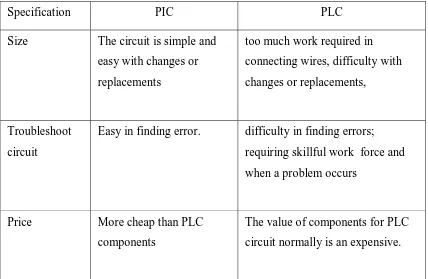
Table 2.1: The advantages of PIC than PLC.
Specification PIC PLC
Size The circuit is simple and easy with changes or replacements
too much work required in connecting wires, difficulty with changes or replacements,
Troubleshoot circuit
Easy in finding error. difficulty in finding errors; requiring skillful work force and when a problem occurs
Price More cheap than PLC components
The value of components for PLC circuit normally is an expensive.
2.3 Overview Of Major Component Involved
2.3.1 Infrared Proximity Sensors