HOME CONTROL SYSTEM
MOHAMAD RAZIF BIN ABDUL RAHIM
MOHAMAD RAZIF BIN ABDUL RAHIM
This report is submitted in partial fulfillment of the requirements for the award of Bachelor of Electronic Engineering (Industrial Electronic) With Honours.
Faculty of Electronic and Computer Engineering Universiti Teknikal Malaysia Melaka
UNIVERSTI TEKNIKAL MALAYSIA MELAKA
FAKULTI KEJURUTERAAN ELEKTRONIK DAN KEJURUTERAAN KOMPUTER
BORANG PENGESAHAN STATUS LAPORAN
PROJEK SARJANA MUDA II
Tajuk Projek : HOME CONTROL SYSTEM
Sesi
Pengajian : 1 0 / 1 1
Saya MOHAMAD RAZIF BIN ABDUL RAHIM
mengaku membenarkan Laporan Projek Sarjana Muda ini disimpan di Perpustakaan dengan syarat-syarat kegunaan seperti berikut:
1. Laporan adalah hakmilik Universiti Teknikal Malaysia Melaka.
2. Perpustakaan dibenarkan membuat salinan untuk tujuan pengajian sahaja.
3. Perpustakaan dibenarkan membuat salinan laporan ini sebagai bahan pertukaran antara institusi
pengajian tinggi.
4. Sila tandakan ( √ ) :
SULIT*
*(Mengandungi maklumat yang berdarjah keselamatan atau kepentingan Malaysia seperti yang termaktub di dalam AKTA RAHSIA RASMI 1972)
TERHAD** **(Mengandungi maklumat terhad yang telah ditentukan oleh organisasi/badan di mana penyelidikan dijalankan)
√ TIDAK TERHAD
Disahkan oleh:
__________________________ ___________________________________
“I hereby declare that this report is the result of my own work expect for quotes as cited in the references.”
Signature :………
“I hereby declare that I have read this report and in my opinion this report is sufficient in terms of scope and quality for the award of Bachelor of Electronic Engineering
(Industrial Electronics) With Honours.”
Signature :………
ACKNOWLEDGEMENT
First and foremost, I would like to take this opportunity to express my sincere gratitude to my supervisor, Mdm. Noor Asyikin Binti Sulaiman for her advice, guidance, motivation and support in completing this final year project. Her guidance and advices always inspire me to seek more knowledge in solving all the difficulties I had faced throughout this project.
Special thanks to my housemate and all my friends of 4 BENE 2011 who have directly or indirectly contributed and spent their precious time helping me to accomplish this project. I wish you all the best in future life and hope you all will have great achievement in life.
ABSTRACT
ABSTRAK
CONTENTS
CHAPTER TITLE PAGE
DECLARATION i
SUPERVISOR APPROVAL ii
DEDICATION iii
ACKNOWLEDGEMENT iv
ABSTRACT v
ABSTRAK vi
TABLE OF CONTENTS vii
LIST OF TABLES x
LIST OF FIGURES xi
LIST OF ABBREVIATIONS xiii
I INTRODUCTION 1
1.1OVERVIEW 1
1.2PROBLEM STATEMENT 2
1.3PROJECT OBJECTIVE 3
1.4SCOPE OF PROJECT 3
1.5 METHODOLOGY 3
1.6 REPORT STRUCTURE 5
II LITERATURE REVIEW 6
2.1 RESEARCH PROJECT 6
2.2 WEB-BASED MANAGEMENT SYSTEM 9
2.2.1 Web Server 9
2.2.2 PHP 10
2.3 COMMUNICATION MEDIUM 11 2.3.1 Serial Communication Interface 11
2.3.2 RS-232 Serial Port 12
2.3.3 USB to UART Converter (UC00A) 13
2.3.4 Local Area Network (LAN) 13
2.4.4 Wide Area Network (WAN) 14
2.5 MICROCONTROLLER SYSTEM 15
2.5.1 PIC16F877A Microcontroller 15
2.5.2 SK40C from Cytron 16
2.6 DRIVER CIRCUIT 17
2.6.1 Relay 17
2.7 SOFTWARE REVIEW 18
2.7.1 Proteus 7.6 18
2.7.2 Adobe Dreamweaver 19
2.7.3 PIC C Compiler 20
2.7.4 Adobe Photoshop 5 20
2.7.5 WampServer 2.1 21
2.7.6 PICkit 2 Programmer 22
III METHODOLOGY 23
3.1 SYSTEM OVERVIEW 23
3.2 HARDWARE DEVELOPMENT 25
3.2.1 Schematic design 25
3.2.2 PCB layout 29
3.3 WEB LAYOUT DEVELOPMENT 33
IV RESULT & DICUSSION 37
4.1 RESULT 37
5.2 SUGGESTION 51
LIST OF TABLE
NO. TITLE PAGE
3.1 Computer to Microcontroller 28
LIST OF FIGURES
NO. TITLE PAGE
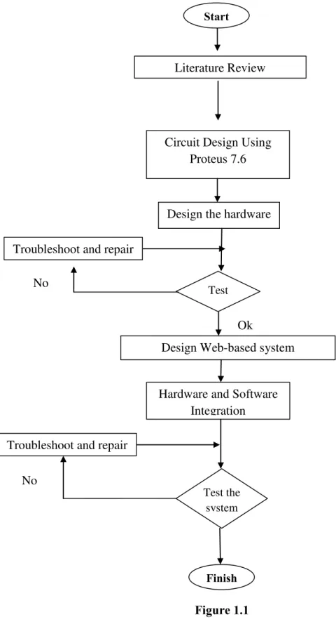
1.1 Methodology Flow Chart 4
2.1 RS-232 protocols 12
2.2 UC00A 13
2. 3 16F877A 16
2.4 SK40C 16
2.5 Relay 17
2.6 Proteus 7.6 19
2.7 Adobe Dreamweaver 19
2.8 PIC C Compiler 20
2.9 Adobe Photoshop 5 21
2.10 WampServer 2.1 22
2.7.5 PICkit 2 Programmer 23
3.1 Flow chart of the system 24
3.2 Complete circuit design 25
3.3 Main circuit 26
3.4 Switching circuit 26
3.5 Virtual computer 27
3.6 Trigger Circuit 27
3.7 Virtual terminal 28
3.8 ARES button 29
3.9 Complete wiring 30
3.13 Web layout development 32
4.1 Start page 38
4.3 Main Page 39
4.4 No input key enter 40
4.5 Off Status 41
4.6 Switch on Lamp 1 41
4.10 Switch on Fan 1 44
LIST OF ABBREVIATIONS
DTE - Data Terminal Equipment
DCE - Data Circuit-termination Equipment GUI - Graphical User Interface
HTTP - Hypertext Transfer Protocol IP - Internet Protocol
ISP - Internet Service Provider I/O - Input / Output
JSP - Java Server Pages LAN - Local Area Network
MAN - Metropolitan Area Network PAN - Personal Area Network PCB - Printed Circuit Board
PIC - Programmable Integrated Circuit SQL - Structured Query Language WAN - Wide Area Network PC - Personal Computer
TTL - Time to live
VPN -Virtual Private Network USB -Universal Serial Bus
CHAPTER I
INTRODUCTION
This chapter will discuss about the introduction, objective, scope and methodology of the project.
1.1 Overview
Internet was developed around 1960, since then it becomes such an important tool for everyone. In 21st century internet is integral part of our modern lifestyle. Internet allows people to do important task flawlessly such as online backing, pay bills, sharing files, and business. Thus, is it possible to give access and control the home appliances over the internet.
This project is a new economical solution of home electrical appliances control systems. The system can be used for different sophisticated electrical appliances such as home light, fan, aircond, television, radio and others electrical device. This control system consists of three basic parts such as personal computer, control circuitry and the electrical devices.
1.2 Problem Statement
Current technology of home appliances control system uses main switch for each appliances and requires human to control the appliances directly. Sometimes users have forgotten whether they have switched ON or OFF the appliances such as lamp or fan when they were away from home. This would cause wastage of the electricity and money. Moreover, cases of burglary are increasing especially during festive season such as Hari Raya Puasa, Tahun Baru Cina, where owner will leave their home for several days without ability to know the current status of their home. Burglaries usually target home that are not occupied. By turning the light ON remotely it will make the home look like occupied with peoples.
Nowadays, computer technology has become more advance as well as internet. Internet subscribers are growing rapidly especially in Malaysia. Lots of ISP (internet service provider) comes up with new package to attract as many subscribers as they can. Network protocol such as 3G, HSDPA, 4G and latest UniFI is some of key element that boosts Malaysian to use internet as part of their daily life. The demand of having remote technology using internet has made this area favorable, thus, it is chosen to be studied and discussed extensively in this thesis.
system, which provides efficient use of energy in a long distance.
1.3 Project Objective
This project attempts:
i. To develop a system that can monitor the status of home appliances and control it regarding user’s need.
ii. To develop a system that can be accessed anywhere either using Ethernet or internet
1.4 Scope Of Project
i) System will use LAN or WAN as a communication medium. ii) Hardware: Using ISIS Proteus 7.6 for simulation.
a) Microcontroller: PIC16F877A combine with SK40C module Communicate using USB to UART.
b) Trigger Circuit: 3V relay.
c) 240Vac Home Light & 13 Amp Socket iii) Programming:
a) Microcontroller: Program written in C# using PIC Complier. b) Webpage: written in PHP language and Dreamweaver CS4. c) Adobe Photoshop CS5 for graphics
1.5 Methodology
hardware. Test the system to ensure it functionalities, and then proceed to designing web-based system. After completed we moved to the final process that is software and hardware integration. Test the system to ensure it working flawlessly and troubleshoot if any problem occurs.
Figure 1.1 Start
Literature Review
Circuit Design Using Proteus 7.6
No
Design the hardware
Test
Ok Troubleshoot and repair
Design Web-based system
Hardware and Software Integration
No
Test the system Troubleshoot and repair
This thesis contains five chapters. The first chapter is about the introduction of the project. It explains the objectives, scope of the project and the problem statement related to the project.
The second chapter is literature review. All the background study that relates to this project will be discussed here. This chapter explains all the hardware and software use in this project.
The third chapter discussed the methodology of the project. This chapter will explain about the method that used to complete this project. Design step of hardware and software are shown in this chapter.
The fourth chapter explains about the result and discussion of the project. The simulation and tested result are discussed further in this chapter.
CHAPTER II
LITERATURE REVIEW
This chapter will explain and discuss about the source and reference that related to the project.
2.1 Research Projects
Zurina Mohd Hanapi [1] in her thesis state the concept of remote control and monitoring becomes an essential feature in many systems nowadays. Remote control allows clients to control their homes from any places, whereas remote monitoring provides the clients the ability to monitor their home or premises when they are away. The key advantage of this application is client has the ability to control and monitor their home remotely for security and safety reasons.
smart home. However, low voltage electrical wiring in homes has largely been dismissed as too noisy and unpredictable to support high-speed communication signals.
Yuta Uesugi, et.al [4] proposes Time Sharing System for In-Home Electric Appliances Using Simple Network Time Protocol. In-home electric appliances obtain the correct time through the Internet by using SNTP. The proposed method was implemented in a verification system with an embedded microprocessor, RTOS and the small resources of 1.8 MB which are assumed to be required for consumer use and was verified. As a result, the correct time was provided with a precision within 1 ms for an SNTP server, and the RTC was able to set it.
Ariff Idris and Anton Satria Prabuwono presented [5] the development of laboratory appliances management system via wireless network for Faculty of Information and Communication Technology-UTeM. The system uses client server communication. The client terminal is used to operate LAMSWi from remote location. It may consist of smart phone, personal digital assistant (PDA), notebook or personal computer (PC) equipped with Bluetooth, WI-Fi or local area network (LAN). The server stores LAMSWi server application and database as well as receiving signal transmitted by client terminal. The experiment result shows the system is able to control electrical appliances from remote location in real time mode via webpage without physically entering specific laboratory. Webpage accessing is done wirelessly via Bluetooth or Wi-Fi. Unfortunately the system is too expensive.