i
“I hereby declare that I have read through this report entitle “Optimization of Solar Panel Positioning for Maximum Energy Conversion” and found that it has comply the partial fulfillment for awarding the degree of Bachelor of Electrical Engineering (Industrial Power)”
Signature :……….………….
Supervisor’s Name :……….……….…
ii
OPTIMIZATION OF SOLAR PANEL POSITIONING FOR MAXIMUM ENERGY CONVERSION
UMMI IMARAH BINTI MAMAT
A report is submitted in partial fulfillment of the requirements for the degree of Bachelor of Electrical Engineering (Industrial Power)
Faculty of Electrical Engineering
UNIVERSITI TEKNIKAL MALAYSIA MELAKA
iii
“I declare that this report entitle Optimization of Solar Panel Positioning for Maximum Energy Conversion is the result of my own research except as cited in the references. The report has not been accepted for any degree and is not concurrently submitted of any other degree”
Signature :……….
iv
v
ACKNOLEDGEMENT
First and foremost, I thank to Allah the Almighty for give me a blessing to complete my Final Year Project II. I would like enlarge my appreciation to En. Azhar bin Ahmad because of his kindness heart to accept me as one of the student under supervision. Special thanks also dedicated to him for all the comments, ideas, supports, and a guideline begin from the first day I start this project and also to En. Mohd Arif bin Mohd Noor as a technician that helps me a lot during my research.
This appreciation also goes out to my friends who always give support, opinion, and advice to me while completing this project. To my beloved family, I would like to forward my obliged to them for their continuous support during my study period, their patience and benevolence. Lastly, I would like to thank to everyone who has any contribution during my Final Year Project II. Your kindness and cooperation is much appreciated.
vi
ABSTRACT
vii
ABSTRAK
viii
TABLE OF CONTENTS
CHAPTER TITLE PAGE
SUPERVISOR DECLARATION i
TITLE PAGE ii DECLARATION iii DEDICATION iv ACKNOWLEDGEMENT v
ABSTRACT vi
ABSTRAK vii TABLE OF CONTENT viii
LIST OF FIGURES xi
LIST OF TABLES xiii
1 INTRODUCTION 1.1 Introduction 1
1.2 Problem Statement 2
1.3 Project Objectives 2
1.4 Scope 3
ix
2 LITERATURE REVIEW
2.1 Introduction 4
2.2 Solar power 5
2.3 Solar system component 6
2.3.1 Photovoltaic cell 7
2.3.2 Storage battery 9
2.3.3 Blocking diode 10
2.3.4 Charge controller 11
2.4 Conversion of sunlight into electricity 12
2.5 Solar cell panel position 14
3 METHODOLOGY
3.1 Introduction 15
3.2 Flow chart 16
3.2.1 Check temperature 17
3.2.2 Setting facing direction 17
3.2.3 Setting the angle 18
3.2.4 Record data 20
3.2.5 Data analysis 23
4 RESULTS
4.1 Introduction 25
4.2 Experiment Results
4.2.1 North 25
x
4.2.3 East 28
4.2.4 West 29
4.3 Final results 30
5 ANALYSIS AND DISCUSSION
5.1 Introduction 31
5.2 Analysis
5.2.1 North 31
5.2.2 South 34
5.2.3 East 37
5.2.4 West 40
5.3 Discussion 43
6 CONCLUSION AND RECOMMENDATION
6.1 Introduction 45
6.2 Conclusion 45
6.3 Recommendation 46
7 REFERENCES 47
xi
LIST OF FIGURES
FIGURE TITLE PAGE
Figure 2.1 Circuit Diagram for Solar System 5
Figure 2.2 Solar panel at FKE 8
Figure 2.3 Battery in solar system 9
Figure 2.4 Solar Storage Battery 10
Figure 2.5 Solar Blocking Diode 11
Figure 2.6 Solar Charge Controller 12
Figure 2.7 The conversion process 13
Figure 2.8 Earth moving around the sun 14
Figure 3.1 Flow chart for the experiment 16
Figure 3.2 Fluke Meter 179 17
Figure 3.3 The compass that used to determine the facing 18
direction
Figure 3.4 Trigonometry equation,sin σ = 18
Figure 3.5 The value of solar panel length and height from 19
ground
Figure 3.6 Solar panel increased based on certain angle 19
Figure 3.7 Measuring tape 20
Figure 3.8 Link that connect outside panel with component in 21
xii
Figure 3.9 Solar panel at FKE 21
Figure 3.10 The connection for Fluke Meter and clamp 22
Figure 3.11 A warning sign 23
Figure 3.12 Solar panel width and length 24
Figure 5.1 Graph of voltage and current vs solar panel angle 31
Figure 5.2 The graph of output power versus solar panel angle 32
Figure 5.3 Voltage and current reading for North with angle 20o 32
Figure 5.4 Voltage and current readings 33
Figure 5.5 Graph of voltage and current vs solar panel angle 34
Figure 5.6 The graph of output power versus solar panel angle 34
Figure 5.7 Voltage and current reading for South with angle 50o 35
Figure 5.8 Voltage and current readings 35
Figure 5.9 Graph of voltage and current vs solar panel angle 37
Figure 5.10 The graph of output power versus solar panel angle 37
Figure 5.11 Voltage and current reading for East with angle 30o 38
Figure 5.12 Voltage and current readings 38
Figure 5.13 Graph of voltage and current vs solar panel angle 40
Figure 5.14 The graph of output power versus solar panel angle 40
Figure 5.15 Voltage and current reading for West with angle 20o 41
xiii
LIST OF TABLES
TABLE TITLE PAGE
Table 4.1 The table for North readings 26
Table 4.2 The table for South readings 27
Table 4.3 The table for East readings 28
1
CHAPTER 1
INTRODUCTION
1.1 Introduction
Nowadays the main sources of generating power system like oil, gas, nuclear power are going more expensive than ever. Besides the price, the amount of non-renewable resources is decreasing and starting to run out while the demands of the world keep rises. If this situation still could not be solved, it can cause a trouble to the world if this is still continuing for a next decade. Besides that, burning fossil can produce greenhouse gases and this gases can make a global warming become faster. In Malaysia, the majority of energy source is from oil. The percentages of the energy sources in Malaysia are 71.4% petroleum, 11.6% hydroelectric power, 8.8% natural gas, 7.6% coal, and 0.5% biomass. Since the world is consuming the energy sources and try to protect the environment, renewable energy are the alternatives in solving this problem. So the main objective is to find a good replacement for such a problem. Renewable energy can be defined as an energy that has been generated from the natural resources such as sun, wind, tidal and others.
2
1883 when Charles Fritz created the first solar cell and began turning solar power into electricity. This was marked as an important moment in the history of solar energy. On 1949 William Grylls Adams had discovered that when light were shined upon selenium, the material shed electrons thereby creating electricity. At Bell Laboratories, Gerald Pearson, Daryl Chapin and Calvin Fuller make a progress about solar cell and on 1953 they developed the first silicon solar cell that works as a semiconductor is capable of generating a measurable electric current.
1.2 Problem Statement
Sunlight position is not static and the position is keep changing from east in the morning and moving to west in the evening before sunset. Since the position of the sunlight is not static, so the sunlight that will produce electricity using PV cells will give a variety output power. This variety of the output power not only depends on the sunlight condition, it also depends on solar cell angle position. Based on this condition, the output power of solar panel will give a different value and not be optimized.
1.3 Project Objectives
The objective of this project is to study about a solar system and the output. However, the main focus is to find the right position for the solar panel in facing the sun. The objectives can be listed as below:-
i) To determine the solar panel angle that can produce the optimum output power. ii) To develop calculation methods for determining the solar panel angle based on the
solar panel height.
3
1.4 Scope
This project will be based on determining the output power from solar cell panel. Besides that, it also will be focused on how to find the suitable solar panel angle in producing the most optimum output power. There are a few solar cell panels at Faculty of Electrical Engineering (FKE) UTeM, so the experiment will be conducted here. The experiment will be done repeatedly hence it will produce a variety of output power.
1.5 Conclusion
4
CHAPTER 2
LITERATURE REVIEW
2.1 Introduction
In writing the literature review, the main purpose is to convey to the reader about the ideas that is want to be established in this project. As a piece of writing, a literature review must be defined by as a guiding concept and the all of the information in it is not only a descriptive list of the material available, or a set of summaries. It must contain all of the important information that will be used in this project.
Literature review is the phase where all the processes happen such as searching, collecting, and analyzing that has been done or published by another researcher. All of the process can be completed through relevant sources such as book, journal, and technical report, proceeding conferences, web pages and others. Literature review could be main references guidance in the process of making this project.
5
2.2 Solar power
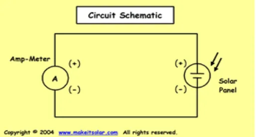
Solar power is energy which comes from the sun. This energy is very powerful and even with the tiny percentage of sunlight that touches the earth will produces plenty of the energy and the power needs of the entire human population more than 8,500 times over. The purpose of solar energy collection is for the output of power, measured in Watts (P= V x I, V=voltage, I=current). However, in order to study how factors affect this output, it is crucial to understand how this performance is evaluated. In Figure 2.1, it shows the basic circuit diagram of solar power system.
Figure 2.1 Circuit Diagram for Solar System
6
rate of delivery of solar radiation per unit of surface. Insolation can be expressed in the units of watts per square meter (W/m2) or kilowatt-hours per square meter (kWh/m2) per day. However, not all the insolation that arrives at the earth's upper atmosphere will be absorbed in earth but half is reflected back into space. In this condition, there is more than enough free solar energy available to power human energy needs. Insolation is affected by Earth's atmosphere and the angle of incidence of sunlight on the atmosphere. On a clear day at sea level, when the sun's rays hit perpendicular to the earth's surface, we receive 1000 W/m2 of insolation. Because Earth is round, the Sun strikes the surface at different angles, from 0 degrees to 90 degrees. At lower degrees, the insolation travels longer through the atmosphere and becomes scattered and diffuse, whereas at higher degrees there are fewer atmospheres to travel through, so more of the sun's energy hits the earth. (Lewis, N. 2005)
Solar power has its own advantage and disadvantage. Since it is come from sun, it is known as a clean renewable energy. Besides that the cost of the source is free and it is also an infinite source. The maintenance for solar power also less rather than other energy source like fossil. However, even the cost of the source is free but the cost for construction the whole solar system is very high. Photovoltaic cells and battery is the main part of the system and because of that it needs a huge space to place all the equipment. In future, if we want to use solar energy as a main source for power system in Malaysia, a very huge placed is needed.
2.3 Solar system component
To make a complete solar system, it depends on a few important components and every part has it own functions. Photovoltaic cells are the most important things that cannot be missed in solar system. However, besides photovoltaic cells there are other components like storage battery, blocking diode, control charger, and inverter.
7
developed and in mass production when solar energy collection technology was developed, and so it was the practical choice.
2.3.1 Photovoltaic cell
“Photovoltaic” is a Greek word which has its own meaning. The meaning of “Photo” is light and “Volt” is the voltage we can get after we make it in a circuit. The photovoltaic effect is the basic principal process by which a PV cell converts sunlight into electricity. When light shines on a PV cell, it may be reflected, absorbed, or pass right through. The absorbed light generates electricity.
Since the mid 1980s there have been dramatic increases in the efficiencies of laboratory demonstration cells. These came from improvements in current, significant increases in voltage, and splitting the sunlight among solar cells of differing bands gaps that waste less of sunlight input power. The higher voltages directly resulted from increases in the density of minority carriers generated by absorbed light.
A photovoltaic device or solar cell is a semiconductor device that can be used to convert light into electricity at the atomic level. Solar cells are made of the same kinds of semiconductor materials, such as silicon, used in the microelectronics industry. For solar cells, a thin semiconductor is specially treated to form an electric field, positive on one side and negative on the other. Semiconductors are not good at conducting electricity and that is what makes them semiconductors. Silicon, for example, forms a crystalline structure. Each molecule is bonded to the electrons of its neighbors, leaving no free floating electrons to move around and create a current. The photovoltaic cells are usually connected in series and parallel to construct a PV module. (Lafferty, K.,1998)
8
proportional to the power that the solar cell delivers. The amount of energy that will be kept is depends the size of PV cells. There are a few types of PV cells such as, amorphous silicon, multicrystalline silicon ribbon silicon and others. PV cells can be made of many different semiconductors but crystalline silicon is the most widely in industry.
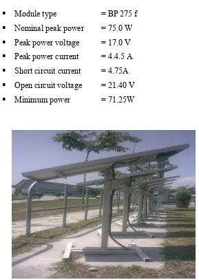
At FKE, there are a few solar panels that will be used in the research. In Figure 2.2 show the solar panel at FKE that will be used in this research. This is a few details about the solar cell panel:-
§ Module type = BP 275 f § Nominal peak power = 75.0 W § Peak power voltage = 17.0 V § Peak power current = 4.4.5 A § Short circuit current = 4.75A § Open circuit voltage = 21.40 V § Minimum power = 71.25W
9
2.3.2 Storage battery
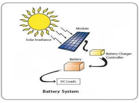
Backup battery charging is essential to most renewable energy systems because there are likely to be occasions when the natural energy supply is insufficient. In solar system, this is another important element that can’t be missed. Many people might confuse and think that at night solar system will not be function. It is not true because solar system has this component that named storage battery. In Figure 2.3 shows the position of the storage battery in solar power system. The batteries are necessary to store the power once the sun does not supply an electrical charge anymore for an example at night or on a cloudy day. During that time, the photovoltaic modules will charges the batteries. Hence the batteries will supplies power to the load as needed.
Figure 2.3: Battery in solar system
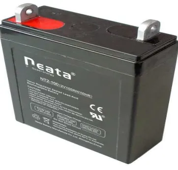
10
Figure 2.4: Solar Storage Battery
Another important thing to be considered is about the process when discharge the batteries. There is one method named Depth of Discharge (DOD). This method is related with the voltage drop before the next charge cycle. Most battery ratings talk about 50% or so, but they will last longer if you keep them as charged as possible. For lead acid batteries is like to be fully charged. They will last much longer if not discharge it too deeply. This is known as shallow cycling and greatly extends their life. However, they can withstand discharges down to 20%.
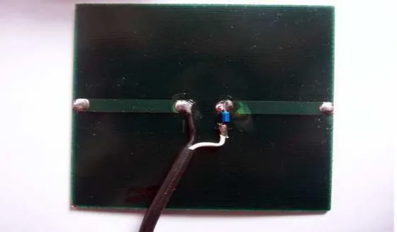
2.3.3 Blocking diode
11
Another function is to block the reverse flow down damaged modules from parallel modules during the day. Blocking diodes placed at the head of separate series wired strings in high voltage systems can perform yet another function during daylight conditions. If one string be comes severely shaded, or if there is a short circuit in one of the modules, the blocking diode prevents the other strings from loosing current backwards down the shaded or damaged string. The shaded or damaged string is “isolated” from the others, and more current is sent on to the load. In this configuration, the blocking diodes are sometimes called “isolation diodes”. (Anon, 2003)
Figure 2.5: Solar Blocking Diode
2.3.4 Charge controller