VALVE FLOW CONTROL USING PWM (PIC)
Ahmad Faizul Bukhari B. Mat Tahir
Bachelor in Mechatronic Engineering
i
“I hereby declared that I have read through this report entitle “Valve Flow Control Using PWM (PIC)” and found that it has comply the partial fulfillment for awarding
the degree of Bachelor of Mechatronic Engineering
Signature : ………
Supervisor’s Name : ……….
ii
VALVE FLOW CONTROL USING PWM (PIC)
AHMAD FAIZUL BUKHARI B. MAT TAHIR
This report is submitted in partial fulfillment of requirements for the degree of bachelor in mechatronic engineering
Faculty Of Electrical Engineering
UNIVERSITI TEKNIKAL MALAYSIA (UTeM)
iii
“I declared that this report entitle “Valve Flow Control Using PWM (PIC)” is the result of my own work except as cited in the references. The report has not been accepted for any degree and is not concurrently submitted in candidature of any other
degree.”
Signature : ………
iv
v
ACKNOWLEDGEMENT
Alhamdulilah, praise be to Allah, the Cherisher and Sustainer of world, most Gracious, most Merciful Lord.
Praise be to Allah for enabling me to completed this Valve Flow Control using PWM (PIC16F877A) Microcontroller project and report for my “Projek Sarjana Muda”.
I would like to thank Pn Intan Azmira bte. Wan Abd Razak as my supervisor, for his priceless help, support and ideas to me during achieving my “Projek Sarjana Muda” goals. Her countless assistance in this project will remind eternally in my mind.
During the accomplishment, I had collaborated with many colleagues for whom I have great regards and I want to extend my warmest thanks to all those who helped me with my work.
vi
ABSTRACT
vii
ABSTRAK
viii
TABLE OF CONTENTS
CHAPTER DESCRIPTION PAGE
DECLARATION i
TITLE ii
DEDICATION iv
ACKNOWLEDGEMENTS v
ABSTRACT vi
TABLE OF CONTENTS viii
LIST OF FIGURES x
LIST OF TABLE xi
LIST OF APPENDICES xii
1. INTRODUCTION
1.1 Background 1
1.2 Project objectives 3
1.3 Problem Statement 3
1.4 Scope of Project 4
1.5 Project Methodology 4
1.6 Summary 6
2. LITERATURE REVIEW
2.1 Introduction 7
2.2 Derive the frequency of a turbine meter 7 2.3 Basic construction of turbine flowmeter 9
2.3.1 Turbine meter 9
2.3.2 Signal output 10
2.4 The PIC16F877A Microcontroller 11
2.4.1 Microcontroller 11
ix
2.4.3 High-Performance RISC CPU 12
2.4.4 Analog Features 13
2.4.5 Special Microcontroller Features 13
2.5 Pulse Width Modulation (PWM) 14
2.6 Servo motor 17
2.6.1 Electrical Specification 17
3. METHODOLOGY
3.1 Introduction 20
3.2 Part A 20
3.2.1 Formula 22
3.2.2 Calculation 22
3.3 Part B 23
3.3.1 Controlling Servo 23
3.3.2 PIC16F877A-IP 25
3.3.3 PIC16F877A-IP Hardware Programmer 26
3.3.4 Controller design 28
3.3.5 Valve flow control fabrication 30
3.4 Project planning 31
4. RESULT & DISCUSSION
4.1 Introduction 32
4.2 Simulation 32
4.2 Hardware Configuration 35
5. CONCLUSION & RECOMMENDATIONS
5.1 Conclusion 36
6. REFERENCES 37
x
LIST OF FIGURES
FIGURE TITLE PAGE
1.1 Flowchart of project 5
2.1 Turbine flowmeter 9
2.2 Pickup coil 10
2.3 The Diagram of PIC16F877A and Its Pin Descriptions Diagram 12
2.4 Types of PWM 16
2.5 Control servo motor using PWM 16
2.6 Servo motor 17
2.7 Anatomy of a servo motor 18
2.8 PWM Waveforms 19
3.1 Flowchart of project 21
3.2 Servo motor block diagram 23
3.3 Pulse Width Modulation for servo motor 24
3.4 Schematic diagram to drive servo motor 24
3.5 PIC 16F877A-IP pin configuration 25
3.6 Shcematic diagram of programmer 26
3.7 JDM programmer 27
3.8 Closed-loop system 28
3.9 Gain scheduling technique’s flow chart 29
3.10 Top view 30
3.11 4 x 4 keypad 30
4.1 Simulation of servo motor 33
4.2 Simulation of keypad 4x4 and LCD 33
xi
LIST OF TABLE
TABLE TITLE PAGE
xii
LIST OF APPENDICES
APPENDIX TITLE PAGE
A 4 x 4 Alphanumeric keypad 39 B1 16 X 2 LCD Module Pins Description 40 B2 16 X 2 LCD Module Electrical Characteristic 41 C Regulators connection and characteristic 42
D PWM Servo Motor Generation 47
E Servo Motor Control 49
CHAPTER 1
INTRODUCTION
1.1
Background
Process plants consist of hundreds or even thousands of control loops that are networked together to produce a product. Each of these control loops is designed to keep some important process variable such as pressure, flow, level, and temperature within a required operating range to ensure the quality of the end product. Each of these loops receives and internally creates disturbances that detrimentally affect the process variable. Interaction from other loops in the network provides a disturbance that influences the process variable.
The most common final control element in the process control industries is the control valve. The control valve manipulates a flowing fluid, such as gas, steam, water, or chemical compounds, to compensate for the load disturbance and keep the regulated process variable as close as possible to the desired set point [1].
2
3
1.2 Project objectives
The main objectives of this project are to design the valve flow control for turbine meter using microcontroller (PIC). This project consists of hardware and software elements. Below are the objectives of the project:
.
1. To design the valve flow control system
2. To develop and design the programming language of the system 3. To design and control the servo motor using microcontroller 4. To control the average flow rate by input data of base frequency
1.3 Problem statement
Microcontroller is more stable compare to the microprocessor in order to generate the pulse width modulation (PWM) waveform. The microcontroller circuit is also simpler and easier to control. Therefore, the microcontroller is cheaper than microprocessor.
4
1.4 Scope of project
With wide variety of turbine meter uses such as in pipelines, this project purposely to design simple valve flow control using PIC 16F877A microcontroller with servo motor to control the average flow rate. In order to achieve the objective of the project, a programming language needs to be developed. Finally the flow rate value will be displayed.
1.5 Project methodology
This section explained the method involved in the project. The first step is gathering information regarding the turbine meter, servo motor, PWM, PIC 16F877A. Then the circuit is designed and simulated using the Proteus Design Suite software to ensure the designing circuit in well operated. Finally, after the circuits are tested, the circuit is fabricated. The figure 1.1 below shows about the flow chart of
5
[image:18.612.162.469.79.663.2]NO
Figure 1.1: Flowchart of project Start
Literature review :
Gather all source or information about the PWM, servo motor, PIC 16F877A and turbine meter
Design:
Design the hardware / control circuit
Design the software / programming language Design the regulator circuit
Design overall control circuit
Simulation:
Simulate the keypad and LCD Simulate the servo motor with PWM
Functioning
Testing overall control circuit
Functioning
End NO
6
1.6 Summary
CHAPTER 2
LITERATURE REVIEW
2.1
Introduction
This chapter introduces the ideas of starting the project. The theory of the flow
control is described in this chapter. These references are used to gain an understanding
of the concepts required to implement a working algorithm which would meet the
project requirements.
2.2 Derive the frequency of a turbine meter
Every turbine flow meter has a unique k-factor or ratio of input pulses per unit of
flow. As the turbine rotates within the flow meter an electronic pulse is created each
time a turbine blade passes the face of the magnet. The total number of pulses equivalent
to
one
unit
of
flow
is
the
k-factor.
Each pulse generated represents a discrete amount of volumetric throughput.
Dividing the total number of pulses generated by the specific amount of liquid product
that passed through the turbine flowmeter determines the K-Factor. The K-Factor,
expressed in pulses per unit volume, may be used with a factoring totalizer to provide an
indication of volumetric throughput directly in engineering units. The totalizer
continuously divides the incoming pulses by the K-Factor (or multiplies them with the
8
output, or number of pulses per unit time, is directly proportional to the rotational rate of
the turbine rotor. Therefore, this frequency of the pulse output is proportional to the rate
of
the
flow.
By dividing the pulse rate by the K-Factor, the volumetric throughput per unit
time of the rate of flow can be determined. Frequency counters or converters are
commonly used to provide instantaneous flow rate indication. Plotting the electrical
signal output versus flow rate provides the characteristics profile or calibration curves
9
2.3
Basic construction of turbine flowmeter
2.3.1 Turbine meter
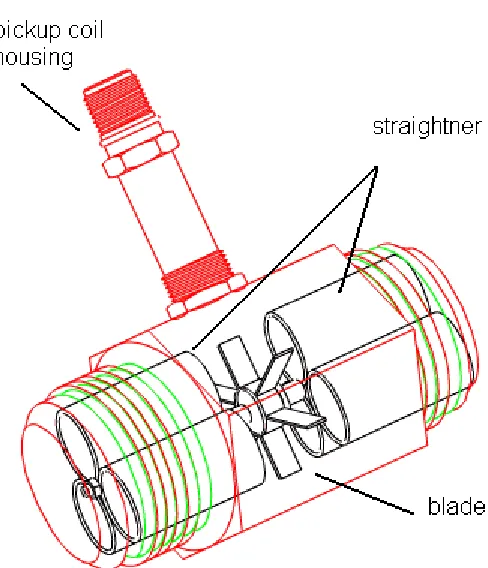
The basic construction of the turbine flowmeter incorporates a bladed turbine
rotor installed in a flow tube. The rotor is suspended axially in the direction of flow
through the tube. The turbine flowmeter is a transducer, which senses the momentum of
the flowing stream. The bladed rotor rotates on its axis in proportion to the rate of the
liquid flow through the tube. Figure 2.1 below show the construction of turbine
flowmeter. The first element of turbine meter is their blade that functions as flux cutter.
Pickup coil housing is where the pickup coil will be placed. It is functions as pulse
generator that will be sent to control monitor. Finally the straightner is an element in
[image:22.612.211.455.361.645.2]stabilizing the flow of liquid through the flowmeter
10
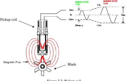
2.3.2 Signal Output
Electrical output is generated using the principle of reluctance. A pickup coil,
wrapped around a permanent magnet, is installed on the exterior of the flow tube or the
meter body immediately adjacent to the perimeter of the rotor (Figure 2.2). The magnet
is the source of the magnetic flux field that cuts through the coil. Each blade of the
turbine rotor passing in close proximity to the pickup coil causes a deflection in the
existing magnetic field. This change in the reluctance of the magnetic circuit generates a
voltage pulse within the pickup coil. Each pulse generated represents a discrete amount
of volumetric throughput. Dividing the total number of pulses generated by the specific
amount of liquid product that passed through the turbine flowmeter determines the
[image:23.612.119.529.360.623.2]K-Factor.
11
2.4
The pic16f877a microcontroller
2.4.1 Microcontroller
A microcontroller (or MCU) is a computer-on-a-chip used to control electronic
devices. It is a type of microprocessor emphasizing self-sufficiency and
cost-effectiveness, in contrast to a general-purpose microprocessor (the kind used in a PC). A
typical microcontroller contains all the memory and interfaces needed for a simple
application, whereas a general purpose microprocessor requires additional chips to
provide these functions.
A microcontroller is a single integrated circuit with the following key features:
central processing unit - ranging from small and simple 8-bit processors to
sophisticated 32- or 64-bit processors
input/output interfaces such as serial ports
peripherals such as timers and watchdog circuits
RAM for data storage
ROM, EEPROM or Flash memory for program storage
clock generator - often an oscillator for a quartz timing crystal, resonator or
RC circuit
This integration drastically reduces the number of chips and the amount of wiring and