UNIVERSITI TEKNIKAL MALAYSIA MELAKA
ANTI-THEFT MOSQUE FUND USING GLOBAL SYSTEM FOR
MOBILE (GSM)
This report is submitted in accordance with the requirement of Universiti Teknikal Malaysia Melaka (UTeM) for the Bachelor of Electronics Engineering Technology
(Industrial Electronics) with Honours
by
MUHAMMAD HIKMAL HAKIM BIN ABD HAMID
B071210192
900524-04-5175
UNIVERSITI TEKNIKAL MALAYSIA MELAKA
BORANG PENGESAHAN STATUS LAPORAN PROJEK SARJANA MUDA
TAJUK: ANTI-THEFT MOSQUE FUND USING GLOBAL SYSTEM FOR MOBILE (GSM)
SESI PENGAJIAN: 2015/16 Semester 1
Saya MUHAMMAD HIKMAL HAKIM BIN ABD HAMID
mengaku membenarkan Laporan PSM ini disimpan di Perpustakaan Universiti Teknikal Malaysia Melaka (UTeM) dengan syarat-syarat kegunaan seperti berikut:
1. Laporan PSM adalah hak milik Universiti Teknikal Malaysia Melaka dan penulis. 2. Perpustakaan Universiti Teknikal Malaysia Melaka dibenarkan membuat salinan
untuk tujuan pengajian sahaja dengan izin penulis.
3. Perpustakaan dibenarkan membuat salinan laporan PSM ini sebagai bahan pertukaran antara institusi pengajian tinggi.
4. **Sila tandakan ( )
SULIT
TERHAD
TIDAK TERHAD
(Mengandungi maklumat yang berdarjah keselamatan atau kepentingan Malaysia sebagaimana yang termaktub dalam AKTA RAHSIA RASMI 1972)
(Mengandungi maklumat TERHAD yang telah ditentukan oleh organisasi/badan di mana penyelidikan dijalankan)
Alamat Tetap:
Tingkat 3D Blok Mawar IPD PD,
Jln. Seremban 71000 Port Dickson,
Negeri Sembilan.
Tarikh: ________________________
Disahkanoleh:
Cop Rasmi:
Tarikh: _______________________
i
DECLARATION
I hereby, declared this report entitled “Anti-Theft Mosque Fund Using Global System For Mobile (GSM)” is the results of my own research except as cited in references.
Signature :………
Name : ………
APPROVAL
This report is submitted to the Faculty of Engineering Technology of UTeM as a partial fulfillment of the requirements for the degree of Bachelor of Electronics Engineering Technology (Industrial Electronics) (Hons.). The member of the supervisory is as follow:
iii
ABSTRACT
ABSTRAK
v
DEDICATIONS
ACKNOWLEDGMENTS
vii
LIST OF FIGURES... xi
LIST OF TABLES... xii
LIST OF SYMBOLS AND ABBREVIATIONS... xiii
CHAPTER 1...1
1.0 Introduction... 1
1.1 Project Background... 1-2 1.2 Problem Statement...2
1.3 Objectives of the Project... 2
1.4 Scope of the Projects... 3
1.5 Methodology...4
CHAPTER 2...6
2.0 Introduction... 6
2.1 Related Research on Control Boards...6
2.1.1 Arduino Uno R3... 7
2.1.2 Raspberry Pi Model B... 8
2.1.3 BeagleBone Black Rev C...9
2.1.4 Comparison of Control Boards... 10
2.2 Related Research on Networking...10
2.2.1 GSM...11-12 2.2.2 Wi-Fi ... 12-13 2.2.3 Comparison of Networking...13
2.3 Related Research on Buzzer... 14
2.3.1 Piezo Buzzer...14
2.3.2 Magnetic Buzzer... 15
2.3.3 Comparison of Buzzer ... 15-16 2.4 Related Research on Emergency light (LEDs)...16
2.5 Related Research on Sensor... 17
2.5.1 Infrared Sensor... 17
2.5.2 Ultrasonic Sensor... 18
2.5.3 Comparison of Sensor... 18
2.6 Review on Related Project... 19
CHAPTER 3...20
ix
3.1 Methodology Framework... 20
3.1.1 Overview of Project Methodology...21
3.2 Details of Framework... 21
3.2.1 Project Study...21-22 3.2.2 Information Analysis...22
3.2.3 Design... 22-23 3.2.4 Development... 23
3.2.5 Testing & Deployment...23-24 3.3 Software and Hardware Components... 24
CHAPTER 4...25
4.0 Introduction... 25
4.1 Manually Power ON the System... 25
4.2 SMS Service Accessibility... 25-27 4.3 Time Analysis...27
4.3.1 Software and Hardware Components...28
4.3.2 SMS Sending Time... 28-30 4.3.3 Delay Based on Distance... 31-33 4.3.4 Coverage of Mobile Networks...33-35 4.4 Distance Detection...36
CHAPTER 5...37
5.0 Introduction... 37
5.1 Objective of Project... 37
5.1.2 Second Objective Achieved... 38
5.1.3 Third Objective Achieved... 39
5.2 Recommendations for Future Improvement...40
5.3 Conclusion... 41 REFERENCES... 42-43 APPENDIX A
xi
LIST OF FIGURES
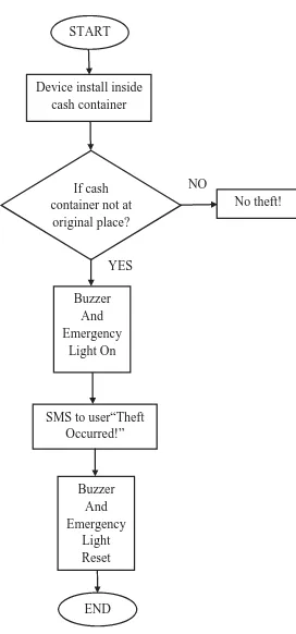
Figure 1.1: Flowchart for whole project... 4
Figure 1.2: Block diagram for whole project... 5
Figure 2.1: Arduino Uno R3... 7
Figure 2.2: Raspberry Pi Model B... 8
Figure 2.3: BeagleBone Black Rev C... 9
Figure 2.4: GSM Logo... 11
Figure 2.5: How SMS works...11
Figure 2.6: Wi-Fi Logo... 12
Figure 2.7: Wi-Fi Router...12
Figure 2.8: Structure of Piezo buzzer...14
Figure 2.9: Structure of Magnetic buzzer... 15
Figure 2.10: Infrared sensor operation... 17
Figure 2.11: Ultrasonic sensor operation... 18
Figure 3.1: Flowchart of Methodology Framework...20
Figure 4.1: SMS Service Accessibility Formula...26
Figure 4.2: Example of Notification... 26
Figure 4.3: Calculation of SMS Service Accessibility...27
Figure 4.4: The Flow of the Message from System to Receiver...29
Figure 4.5: The Location of System and Points... 31
LIST OF TABLES
Table 2.1: Comparison between types of control board... 10
Table 2.2: Comparison between types of networking technology... 13
Table 2.3: Comparison between types of buzzer... 15
Table 2.4: Comparison of chip technologies for wide-angle, non-diffused LEDs... 16
Table 2.5: Comparison between types of sensor...18
Table 3.1: Overview of Project Methodology...21
Table 3.2: System Components...24
Table 4.1: Result of Service Accessibility... 27
Table 4.2: Response Time of the System...28
Table 4.3: SMS Sending Time... 29
Table 4.4: The Total Time Taken for User Received Notification... 30
Table 4.5: Name of Location... 32
Table 4.6: Delay Based on Distance... 32
Table 4.7: Total Time for Digi Mobile Network... 33
Table 4.8: Total Time for Maxis Mobile Network... 34
Table 4.9: Total Time for Celcom Mobile Network... 34
Table 4.10: Total Time for U Mobile Mobile Network... 34
xiii
LIST OF SYMBOLS AND ABBREVIATIONS
LED = Light Emitting Diode GSM = Global System for Mobile USB = Universal Serial Bus
I/O = Input Output DC = Direct Current
GPU = Graphics Processing Unit RAM = Random Access Memory
GHz = Gigahertz
MHz = Megahertz
KHz = Kilohertz
MB = Megabyte
GPIO = General Purpose Input/Output PC = Personal Computer
TV = Television
SMS = Short Message Service SMC = Short Message Center SME = Short Message Entity HLR = Home Location Register
GMSC = Gateway Mobile Switching Centre MSC = Mobile Switching Centre
BSS = Base Station System SPL = Sound Pressure Level
dB = Decibel
mA = Milliampere
PIC = Peripheral Interface Controller
1
CHAPTER 1
INTRODUCTION
1.0 Introduction
This chapter elaborates the overview and the brief explanation of this research. It is followed by the project background, problem statement, objectives, scopes, and the significance of this project. Besides that, this research also will elaborates the current situation and issues that are being faced which led to this research.
1.1 Project Background
Mosque is a place for Muslims to worship. Furthermore, they will donates money before they leave the mosque at the specific cash container placed in the mosque. However, nowadays criminals will steal the mosque cash container. With the installation of anti-theft mosques funds, expected that it will help mosque committee members to control the theft cases that occur in their area and indirectly can reduce cases of the same in other places. It can be activated at any time without human supervision twenty-four hours. This is because the system itself will notify responsible person of mosque if the theft occur.
to help reduce thefts occurring. Basically, the system uses the Global System for Mobile (GSM) that will notify the responsible person of mosque. This system also be connected with a buzzer and emergency light. Furthermore, responsible person of mosque can enable and disable it.
1.2 Problem Statement
There are several problems that happen based on the mosque cash container. The problem statement as
shown:-i. Thief usually steal mosque cash container when other people do worship and nobody around the mosque.
ii. Even though closed-circuit cameras installed but theft still occurs because theft happen when nobody around the mosque.
iii. Mosque committee members cannot control the area surrounding of the mosque for twenty-four hours a day a week.
iv. Mosque committee members may forgot to lock the mosque.
1.3 Objectives of the Project
The main objective of this project is to build a system to be implemented at mosque on cash container without human supervision. The objectives as
shown:-i. To using mechanism of sensor as a main point before message notification is sent to responsible person of mosque activated.
ii. To construct the buzzer and emergency light that produce sound and light respectively which is alert if theft occurs.
3
1.4 Scope of the Project
This project can be divided into two parts which is hardware and software approach implementation. The scopes of the project as
shown:-i. Sensor will range the distance of mosque cash container that will connected to Arduino.
ii. When Arduino receive signal from sensor means that the mosque cash container not at original place.
iii. Buzzer and emergency light will turn on.
1.5 Methodology
NO
YES
5
1.6 Block Diagram
Figure 1.2 : Block diagram for whole project SENSOR
EMERGENCY LIGHT
CHAPTER 2
LITERATURE REVIEW
2.0 Introduction
This chapter will explain the related articles. The articles will be utilizes as references and guidelines for this project to be done. It can give a considerable measure of great thought to make a great exploration. This chapter reviews the available literature managing for this project.
2.1 Related Research on Control Boards
7
2.1.1 Arduino Uno R3
Figure 2.1 : Arduino Uno R3
The diagram above shows the Arduino Uno R3. This is the latest board from Arduino with an USB interface chip. This has an expanded shield header with a 3.3V reference and a RESET pin and a 21 500mA fuse to protect your computer's USB port, but as well as an automatic circuit to select USB or DC power without a jumper. This board is pin and code-compatible. This board also has an USB interface chip and additional breakouts for the i2c pins and an IO Ref pin (Arduino, 2013).
2.1.2 Raspberry Pi Model B
Figure 2.2 : Raspberry Pi Model B
The diagram above shows the Raspberry Pi Model B. Raspberry Pi Model B is a control board, which is actually a computer by itself. It is a single-board computer developed with the intention of stimulating the teaching of basic computer science. The design is based on a Broadcom BCM2835 system on a chip, which includes an ARM1176JZF-S 700 megahertz processor, VideoCore IV GPU, and 512 megabytes of RAM. The SD Card slot acts as a slot for storage (Raspberry Pi, 2013).