i ANTI THEFT TRACKING SYSTEM REMOTE USING GSM
MUHAJIR B MUSTAPA KAMAL
This report is submitted in partial fulfillment of the requirement for the award of Bachelor of Electronic Engineering (Wireless Communication) With Honours
Faculty of Electronic and Computers Engineering University Teknikal Malaysia Melaka
viii ABSTRACT
ix ABSTRAK
ix TABLE OF CONTENTS
CHAPTER TITLES PAGE
TITLE OF PROJECT i
REPORT STATUS FORM ii
DECLARATION iii
DEDICATION v
ACKNOWLEDGEMENT vi
ABSTRACT vii
ABSTRAK viii
TABLE OF CONTENTS ix
LIST OF TABLE xii
LIST OF FIGURE xiii
LIST OF ABREVIATION xv
LIST OF SYMBOL xvi
LIST OF APPENDICES xvii
1 INTRODUCTION
1.1 Introduction 1
1.2 Problem Statement 2
1.3 Objective 3
1.4 Thesis Layout 4
2 LITERATURE REVIEW
2.1 Introduction 5
x 2.1.2 Common Methods Used by Thieves to
Steel Cars 8
2.2 Preview Works Related to the Proposed Project 10
2.3 SIM908 11
2.3.1 Power supply 11
2.3.2 Power on SIM908 13
2.3.3 Serial interfaces 15
2.3.4 SIM card interface 16 2.4.5 GPS Application Interface 17 2.4.6 GPS Power on/down Scenarios 17
2.5 Arduino Mini Pro 18
2.5.1 Operation Power 18
2.5.2 Input and Output 19
2.5.3 Programming 20
2.6 AT command 21
2.6.1 Basic syntax 21
2.6.2 S Parameter syntax 21
2.6.3 Extended Syntax 22
3 METHODOLOGY
3.1 Overview 23
3.2 Project Structure 24
3.3 Hardware Design 25
3.3.1 Arduino Mini Pro (Main Controller) 26
3.3.2 GPS/GSM Module 27
3.3.3 PIR Sensor Module 28
3.3.4 Relay Circuit 29
3.4 Software Development 30
3.4.1 General Flow Cart of the Controlling
Program of the Proposed System 30
4 RESULT & DISCUSSION
4.1 Software Test 37
xi
4.1.2 Receive SMS 39
4.1.3 Obtain GPS Information 40 4.1.4 Save and load SMS inside EEPROM
GSM/GPS module 41
4.1.5 PIR Sensor 42
4.1.6 Relay Circuit 43
4.2 System Functionality Test Results 44
4.2.1 Tracking System 44
4.2.2 Immobilize System 46 4.2.3 User Safety System 48
4.2.4 Alarm System 51
5 CONCLUSION AND RECOMMENDATION
5.1 Conclusion and Recommendations 52
REFERENCES 53
APPENDIX A: Source Code for Bus Detection 54
APPENDIX B: Arduino Mini Pro Schematic 70
xii LIST OF TABLES
TABLE TITLE PAGES
2.1 GPS operation mode 17
2.2 Arduino Mini Pro pin description 18
2.3 Arduino GPIO description 19
2.4 AT command operation 22
xiii LIST OF FIGURES
FIGURE TITLE PAGES
2.1 Overall system structure diagram 9
2.2 Working flow diagram 10
2.3 Reference circuit of the LDO power supply 11 2.4 Reference circuit of the DC-DC power supply 12 2.5 Powered on/down module using transistor 13 2.6 Powered on/down module using button 13
2.7 Timing of power on module 14
2.8 Connection of the serial interfaces 15 2.9 Connection of RXD and TXD only 15 2.10 Reference circuit of the 8-pin SIM card holder 16 2.11 Reference circuit of the 6-pin SIM card holder 16
3.1 System block diagram 24
3.2 Connection all module and component 25
3.3 Arduino Mini Pro 26
3.4 Connection between Arduino and USB-UART Converter 26
3.5 GSM/GPS module 27
3.6 (a) PIR Sensor Module front view, (b) PIR Sensor
module back view 28
3.7 Relay Circuit schematic design using Proteus Software 29
3.8 Main loop 30
3.9 initial() function 31
3.10 load() function 32
3.11 check() function 33
3.12 send_GPS() function 34
xiv
3.14 save() function 36
4.1 (a) Serial data from Arduino to GSM/GPS module,
(b) SMS receive 38
4.2 (a) Serial data from GSM/GPS module to Arduino,
(b) SMS send 39
4.3 String form GSM/GPS module to Arduino 40 4.4 (a) String from Arduino to GSM/GPS module
(save SMS), (b) String from GSM/GPS module
to Arduino (load SMS) 41
4.5 Arduino Serial Monitor show “detected” String 42 4.6 LED turn off after push the switch 43 4.7 response after send “Gps on” tracker device 44 4.8 Response after send “Gps off” to tracker device 45 4.9 Response after send “locate” to tracker device 45 4.10 (a) response after send “lock” to tracker device,
(b) LED turn off 46
4.11 (a) response after send “unlock” to tracker device,
(b) LED turn on 47
4.12 response after send “Change password \n <old password> \n <new password> \n
<new password>” to tracker device 48 4.13 Response after send “Change owner \n
<owner number phone> \n <password>” to tracker
device 49
4.14 “ACCESS DENIED” when wrong number send the
SMS 50
4.15 The device send SMS to the owner when detect
xv LIST OF ABREVIATION
LIST OF ABBREVIATION
SYMBOL DEFINITION
GSM Global System Mobile IC Integrated Circuit
GPS Global Positioning System
xvi LIST OF SYMBOL
SYMBOL DEFINITION
Gnd Ground
Tx Transmiter
Rx Receiver
xvii LIST OF APPENDICES
APPENDIX TITLE PAGES
A Source Code for Tracking System 54
B Arduino Mini Pro Schematic 70
1 CHAPTER 1
INTRODUCTION
1.1 Introduction
Now days, the statistical reports of thefts of automobile shows that drastically rising especially motor car at all over the world. This bad situation cause all over the world especially Europe has started worrying for the past of years. Indirectly, the insurance provider has started make new guideline for automobile manufacture to produce their product more secure.
2
1.2 Problem Statement
Based on the data and discussion on automobile theft, this theft cases is a problem all over the world. No one wants his vehicle stolen. Customers who make insurance claims resulting insurance companies feel pressured. This situation resulted increasing the price of insurance premiums by insurance companies. Therefore, insurance premiums affordable for low percentage of customers. Security weaknesses that are installed in the automobile causing automobile insurance premiums increased the price.
3
1.3 Objective
The main objective of this project is to develop, design and test the vehicle anti-theft tracking system using GSM remote that can be used to disable the vehicle and locate the vehicle’s user. The proposed system also allows the user to disable the vehicle and locate the current position of the vehicle remotely by SMS.
Objective and achievement of this project are:-
i. Develop and design based on the proposed hardware system.
ii. Develop software coding based on the proposed control system.
4
1.4 Thesis Layout
This thesis contains five chapters and summarized as follows:-
i. Chapter 1 it about the background of the project, which consists of an introduction, problem statement, and objectives project.
ii. Chapter 2 it regarding the literature review. It is reviewing on vehicle theft, statistics of stolen vehicle, rules and methods used by thieves to steal the car. It also discusses the previous project been used or developed by other researchers associated with this project.
iii. Chapter 3 it regarding the design procedures used to make software and hardware based on the proposed project.
iv. Chapter 4 it regarding the results and a discussion of all the tests conducted for this project.
5 CHAPTER 2
LITERATURE VIEW
2.1 Introduction
One of the social problems in the community is vehicle theft. Contributing to this problem was found several factors including:-
i. The effect of the gap between the rich and the poor are falling further. This is among the reasons for dissatisfaction among the people. This condition occurs due to causes of crime and car theft is one crime that provides opportunities for good returns.
6 iii. Current security system is not effective and the vehicle owner carelessness did not
help for against the crime
Every state of the country and found many forms of vehicle theft. Most crime using common equipment and brute force to unlock the vehicle. Locks and security system provides little deterrent to a skilled thief vehicles.
Moreover, there are two types of vehicle thieves among them "of" the vehicle and "from" the vehicle. Thieves "of" the vehicle consists of a professional thief who stole a car to get parts and accessories, and even change the identity of the vehicle for resale. The second "from" the vehicle, the thief only stole personal items, accessories and spare parts of vehicles. Sometimes, these thieves will stops momentarily committing crimes to avoid suspicion.
7 2.1.1 Statistic of Stolen Car
Statistic by private cars stolen in 1980-1995 shows a decrease every year. After 2000, there was an increase in the number of private cars stolen significantly. In 1980-1995, a total of 5958 private cars stolen average every year. In 2005-2009, this number drastically increased more than 3.5times to 21.501 private cars are stolen every year [5].
8 2.1.2 Common Methods Used by Thieves to Steel Cars
There are many ways thieves steal vehicles such as: -
i. Keys Stolen in Burglary one of the most popular among thieves. This method increases due to increased vehicle safety systems, especially on luxury vehicles stolen by thieves is very difficult without a key [7]. Thieves will break into the
victim's house just to steal the keys inside house.
ii. Keys Left in Car is the second most common method used by thieves. Thieves will steal the vehicle when victim left the keys inside the vehicle when paying for petrol, heating the vehicle on a cold morning and went to the convenience store [7].
Thieves will take the opportunity to bring victim vehicle to another place.
9
2.2 Preview Works Related to the Proposed Project
An Automotive Security System for Anti-Theft is one method that has been proposed to enhance effective vehicle security system. The proposed method uses the GSM modem, and PIC microcontroller.
The structure of the proposed system is:-
Figure 2.1: Overall system structure diagram
10 The software design of the proposed system is:-
11
2.3 SIM908
2.3.1 Power supply
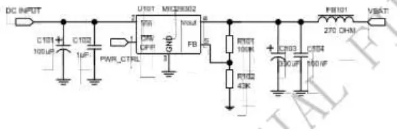
The power supply range of SIM908 is from 3.2V to 4.8V. The transmitting burst will cause voltage drop and the power supply must be able to provide sufficient current up to 2A. For the VBAT input, a bypass capacitor such as a 100uF is strongly recommended, this capacitor should be placed as close as possible to SIM908 VBAT pins. The following figure is the reference design of +5V input power supply. The designed output for the power supply is 4.1V, thus a linear regulator can be used [2].
Figure 2.3: Reference circuit of the LDO power supply
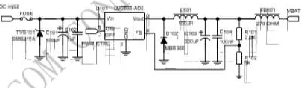
12 Figure 2.4: Reference circuit of the DC-DC power supply
The single 3.7V Li-ion cell battery can be connected to SIM908 VBAT pins directly. But the Ni-Cd or Ni-MH battery must be used carefully, since their maximum voltage can rise over the absolute maximum voltage of the module and damage it [2].
When battery is used, the total impedance between battery and VBAT pins should be less than 150mOhm. The following figure shows the VBAT voltage drop at the maximum power transmit phase, and the test condition is as following [2]: