DOI: 10.12928/TELKOMNIKA.v11i3.1080 451
Controlling Chaos and Voltage Collapse using Layered
Recurrent Network-based PID-SVC in Power Systems
I Made Ginarsa*1, Agung Budi Muljono2, I Made Ari Nrartha3 Dept. of Electrical Engineering, Mataram University
Jln. Majapahit No. 62 Mataram, Telp/fax+62 370 636755
*Corresponding author, e-mail: [email protected], [email protected], [email protected]
Abstrak
Chaos dan voltage collapse muncul pada sistem tenaga listrik akibat gangguan energi pada beban kritis. Untuk mengatasinya maka dirancang PID-SVC yang berbasis-layered recurrent network (LRN).PID berbasis-LRN berfungsi untuk mengatasi chaos dan voltage collapse.Sementara itu, SVC berbasis-LRN berfungsi untuk mengatur tegangan beban. Hasil simulasimenunjukkan bahwa kontroler ini mampu mengatasi chaos dan voltage collapse pada sistem tenaga listrik. Lebih jauh lagi, kontroler ini mampu mengatur tegangan beban dengan cara mensuplai daya reaktif dari SVC. Respons dari kontroler yang diusulkan juga lebih baik dari PI-SVC.
Kata kunci: chaos, voltage collapse, PID-SVC, recurrent network, perbaikan tegangan
Abstract
Chaos and voltage collapse occurred in critical power systems due to disturbing of energy. PID-SVC layered reccurrent neural network-based (LRN-based PID-PID-SVC) was proposed to solve these problems. The PID is used to control chaos and voltage collapse. Meanwhile, an SVC LRN-based is used to maintan the load voltage. By using the proposed controller, chaos and voltage collapse are able to suppress and maintain the load voltage around the setting value. When the maximum load isforced to load bus, the reactive power supplied by SVC, SVC additional voltage and load voltage are at the values of j0.1127, 4.0095103 and 0.980010 pu, respectively. Furthemore, the proposed controller gives better response than PI-SVC controller.
Keywords: chaos, voltage collapse, PID-SVC, recurrent network, voltage maintain
1. Introduction
The Loading on electric power systems (EPS) was growth rapidly. On the other hand, the built of power plants and transmision line were very slow due to economical and environtment reasons. Therefore, the existing EPS must be operated in critical condition on boundary of stability regions. Meanwhile, voltage collapse was found at the highest loading parameter existed on saddle node bifurcation (SNB) and voltage collapseanalysis was done by using center manifold with static and dynamic approach [1]. The appeared of Hopf bifurcation (HB), chaos, crisis and voltage collapse before SNB were identified and classified in [2-3]. The appeared of HB in critical EPS was suppressed by using linear and nonlinear controllers in [4-5].Chaos appeared in rotor speed, angle and voltage magnitude due to disturbingof energy (DE) [6]. Furthermore, chaotic behavior was observed in power systems and modelled using Elman recurrent neural networks (RNN). To validate the RNN model was compared to mathematical model, where the results of the both models were identical [7]. Controlling chaos and voltage collapse using continuation technique [8], ANFIS-based composite controller (CC)-SVC [9] and an additional PID-loop [10]. Artificial neural network(NN) was used in indentification system and control application[11-13]. SVC controlled by NN was used to enhanched dynamic stability of EPS [14] andRNN was used as power system stabilizer in single machine [15].
Section 3. Next, Chaos oscillation, voltage collapse and controller application, result and analysis are described in Section 4. Finally, the conclusion is provided in the last section.
Table 1. Power System Parameters
Y0 Ym 0, m V0 Vm
20.0 5.0 5.0 1.0 1.0
Pm M D T C
1.0 1.0 0.3 0.05 8.5
Kp Kpv Kq Kqv Kqv2
12.0 0.3 0.03 2.8 2.1 All parameter values are in pu except for
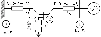
angle, which are in degrees. Figure 1. Three-bus power systems
2. Power System Model
A synchronous generator was connected to infinite bus therefore it was modeled by using a voltage ( ) behind a direct reactance ( ). When the synchrounous generator was operated in normal condition, the voltage magnitude was assumed as remaining constant at pre-disturbance [16]. The power systems supplied the balanced static load with saturation and the stator resistance were neglected. Then the armature current flowed from the generator to the load. Electrical torque was produced on stator winding due to the armature current. Therefore, the mechanical torque was produced by flux on the rotor winding. The rotor speed followed the synchrounous speed in the normal operating condition. Meanwhile, when there was inbalanced energy in the generator, the rotor speed accelerated or decelerated. This condition can be expressed as a swing formula.
∆ 1⁄ (1)
where Tm, Te, , D and M are the mechanical torque, electrical torque, rotor speed deviation,
damping constant and inertia constant, respectively.
In this research, the system was adopted from the work of Chiang et al. [1],as shown in Figure 1. This model represents the system as a synchronous generator that supplies power to an induction motoras local dynamic load with a shunt capacitor (Bus 2) connected by a weak tie line to an external system. By using parameters in Table 1 and put onthe Eqs. (2-4) in [9,10]the parametersV0, Y0 and 0were obtained at the values of 2.5 pu, 8.0 pu and 0.209rad, respectively. Therefore, power system equations are expressed as Equation 2-5.
∆ (2)
∆ 1⁄ ∆ sin sin (3)
1⁄ (4)
1⁄
(5)
where the variables m, , , V, P and Q are the power angle, rotor speed deviation, voltage
angle, voltage magnitude, real and reactive power, respectively. The variables P and Q are computed using Eqs. (6) and (7), respectively.The parameters P1, Q1 and D are the real load, reactive load and damping constant, respectively. The initial real (P0) and reactive (Q0) loads were taken at the values of 0.6 and j1.3 pu, respectively. And the parameter u() was implemented as a control signal of power systems.
sin sin sin sin (6)
3. Layered Recurrent Neural Network-based PID-SVC Design 3.1. PID Controller
PID controllerhas been extensively used by industries and researchers due to their simple structure, which can be easily understood and implemented. In this research, the main focus was to eliminate steady state error as well as to improve the dynamic response. The elimination of steady state error was realized by adding a pole at the origin using an integral controller. Furthermore, transient response was improved by the actionof differential controller. The PID transfer function [17] is expressed as follow:
(8)
where G(s), kp, ki, kd and s are the transfer function, proportional gain, integral gain, differential
gain and Laplace operator, respectively.In this training stage, the P, I and Dgains weretaken at the values of 0.092, 0.0032 and 0.0058, respectively.
3.2 Static Var Compensator (SVC)
Static var compensator was shunt-connected static generator and/or absorber whose output was varied so as to control specific parameter of a power system. The term static was used to indicate that SVC has without any moving or rotating component [16: 693]. Let us start with SVC that was applied at bus k, and the reactive power was injected to bus k
(9)
where Bsvc=BcBl,Bsvc, Bc and Bl are the SVC, capacitive and inductive susceptances,
respectively. Then, dynamic equation of SVC is written as follow [18]:
∆ 1 ∆ ∆ ∆ ∆ (10)
where tsvc, tv1, tv2, kv, Vss-svc, Vr-svc, Vt-svc and Vref are the SVC time constant , time constant 1, time constant 2, SVC gain, SVC voltage at steady state, difference of reference and SVC voltage, difference of terminal and SVC voltage and reference voltage, respectively. In this training stage, the parameter values of SVC for the tsvc, tv1, tv2 and kv were 70.0, 3.073-21.79, 400.0 and 30.0, respectively. The reference voltage was taken at the value of 0.98 pu.
3.3. Layered Recurrent Network (LRN) Design Processes
A detailed method of LRN-based PID-SVC design is presented as follows:
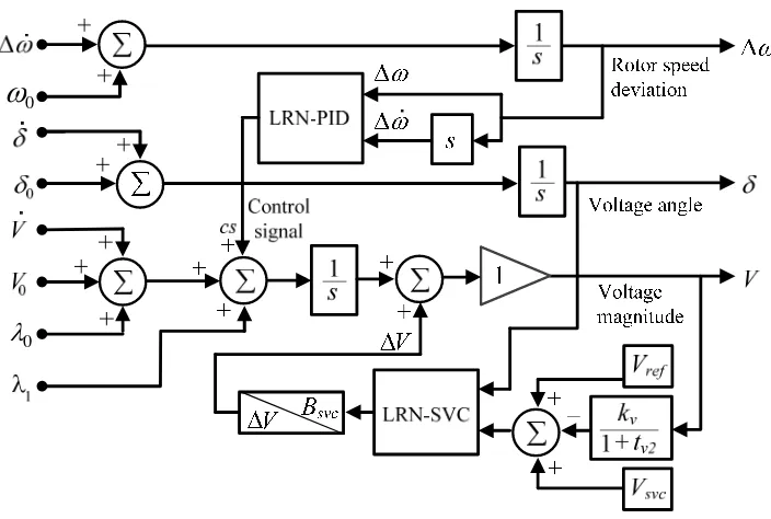
1. Selection of input-output variables: The rotor speed deviation () and its derivative (∆ ) were chosen as the input of LRN-based PID. The output was the control signal (cs). Meanwhile, the voltage angle () and voltage magnitude (V) were chosen as the input of the LRN-based SVC. And the output was the SVC susceptance (Bsvc).
2. Arhitectures of LRN-based PIDand SVC were builtusingthreerecurrent layers and a feed forward layer.First layer (Layer1) was consist of ten neurons, input weight (w11), recurrent
weight1 (w12), bias (b1) and tangent sigmoid activation function (tansig).Second layer (Layer2)
was consist of ten neurons, input weight (w21), recurrent weight1 (w22), bias (b2) and tangent
sigmoid activation function (tansig). Third layer consist of a neuron, input weight3 (w31),
recurrent weight1 (w32), bias (b3) and tangent sigmoid activation function (tansig). And, fourth
layer consist of a neuron, input weight (w41), bias (b4) and linear activation function (purelin).
3. In this training process, the data matrixswith 2×6000 for input data,1×6000for target data and in 100 epochs were used.Gradient descent backpropagation with adaptive learning rate (traingdx) and mean squared error (MSE) [19] were used for learning function and test performance function, respectively.
2.5068 and 0.8979 for LRN-PID and LRN-SVC, respectively. The bias4(b4) parameters
were at the values of 1.0397and 0.2531for LRN-PID and LRN-SVC, respectively.
5. After the training process was completed and the parameters of the LRN-PID and LRN-SVC were obtained, then the proposed controller was applied to power systems. The power systems with the proposed controller is shown in Figure 4.
Figure 2. Architecture of PID-LRN with 10-10-1-1 layers.
Figure 3. Architecture of SVC-LRN with 10-10-1-1 layers.
0
0
4. Results and Analysis
In order to demonstrate the performance of the LRN-based PID-SVC to control chaos and voltage collapse in power systems, the systems were examined using Matlab/Simulink 7.9.0.529 on an Intel Core 2 Duo E6550 233 GHz PC computer.
4.1 Power Systems Without Control Device
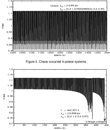
Power systems without any control device are very vulnerable, especialy when these systemsare operated in critical loading.Figure 5 shows chaotic oscillation of power systems when theywere operated on initial condition (x0) at the value of [0.2 1.6700529800344 0.3 0.97]. In this operation, the load voltage magnitude (V)was nonlinear oscillatedin the range of 0.82 -1.12 pu. Therefore, Figure 6 shows the voltage collapse mechanism occurred at time of 442.315 s when power systems were operated at initial condition [0.2 1.2 0.3 0.97] and critical loading at the value of j10.898 pu.Chaos and voltage collapse phenomena are serious problem in power system operation.Blackout phenomenon will occur at the overall of power systems if they are not able to control properly.To overcome of chaos and voltage collapse problems, it is decided to use LRN-based PID-SVC (proposed controller) in power systems. The performance of the proposed controller is analyzed in the next section.
Figure 5. Chaos occurred in power systems
Figure 6. Voltage collapsemechanism of power systemswhen operatedin critical loading.
4.2. Power Systems with LRN-based PID-SVC Application
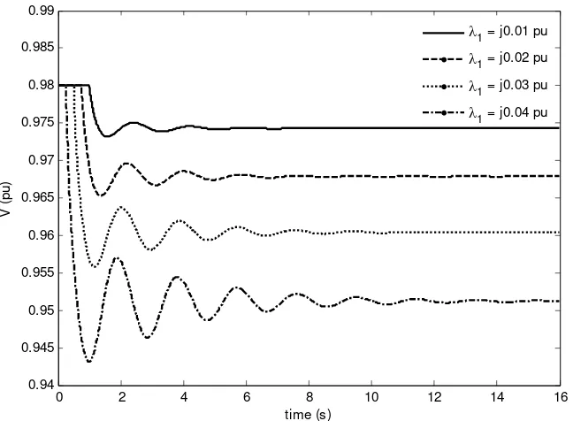
First Scenario, power systems were equipped by LRN-based PID. In this scenario, both chaos and voltage collapse were adequate to suppress in power systems. However, performance of the controller was not good enough. The voltage magnitude (V) was not able to maintain at setting value and the voltage magnitude was still varied according to load value at the load bus.Figure 7 shown that the voltage magnitude was at the value of 0.98 pu when the additional reactive load at the value of j0.0 pu. Furthermore, the voltage magnitude was decreased to 0.9743, 0.9662, 0.9613 and 0.9522 pu when the additional reactive load was forced at the values of j0.01, j0.02, j0.03 andj0.04 pu, respectively. The voltage magnitude was at a low value when a high loading. On the contrary, the voltagemagnitude at a high value when the loading was at a low value.In order to maintain the voltage magnitude at a setting value therefore LRN-based PID was equipped by LRN-based SVC. Performance of the proposed controller was evaluated in the next scenario
Second Scenario: LRN-based PID-SVC (proposed controller) was applied to power systems and load buswas forced by using four additional reactive loads at the values of j0.01, j0.02, j0.03 and j0.04 pu. Simulation results of this scenario are shown Figure 8-12 and listed in Table 2.
Figure 7. Power systems were equipped by LRN-based PID and forced by reactive load at the values of j0.01, j0.02, j0.03and j0.04 pu.
Table 2. Simulation results of power systems when additional loads were forced to load bus at the values of j0.01, j0.02, j0.03 and j0.04 pu.
1(j pu) Vno(pu) Bsvc (j pu) Qsvc (j pu) V(103pu) V(pu)
0.01 0.9743 0.0173 0.0166 0.5853 0.980038
0.02 0.9671 0.0396 0.0380 1.3431 0.980047
0.03 0.9573 0.0733 0.0700 2.4828 0.980033
0.04 0.9427 0.1183 0.1127 4.0095 0.980010
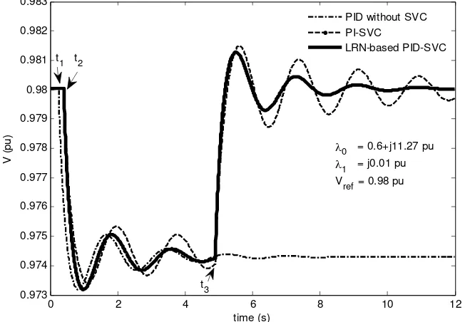
Figure 8 shows responses of PID, PI-SVC and the proposed controller. When power systems were equipped by PIDcontroller without SVC, then an additional load was forced at time t1(0.5 s), voltage magnitude was decreased and oscillated in around 6.3 s.
0 2 4 6 8 10 12 14 16
0.94 0.945 0.95 0.955 0.96 0.965 0.97 0.975 0.98 0.985 0.99
time (s)
V
(
pu)
Figure 8. Comparison of PID, PI-SVC and LRN-based PID-SVCresponses when additional load was forced to power systems at timet1; t2 and the SVC was switched on at time t3.
Furthermore, the voltage magnitude was damped and setlled at the value of 0.9746 pu. When power systems were equipped by PI-SVC, an additional load was forced at (t2 = 0.6 s).
The voltage magnitude was decreased and oscillated with minimum voltage at around 0.9732 pu. At t3 = 4.5 s the SVC was fired and the voltage magnitude was increased and oscillated with
maximum voltage was obtained at the value of 0.9815 pu. Furthermore, the voltage magnitude was damped and settled at the value of 0.98 pu and the settling time more than 12 s. When power systems were equipped by the proposed controller (LRN-based PID-SVC), an additional load was also forced at t2 and the voltage magnitude also decreased around 0.9743pu. At t3 the
SVC was switched on and the voltage magnitude was increased to maximum voltage at the value of 0.9805 pu. Moreover, the voltage magnitude was oscillated and damped undergo to magnitude at 0.98 pu and settling time at time of 9.6 s. From Figure 8 we can see that the response of the proposed controller was better than the other controller where maximum voltage and settling time of the proposed controller were obtained less than the other.
4.3. Power Systems Disturbed by Variation Additional Load a. Power system disturbed by additional load at j0.01 pu
In this scenario, the proposed controller was applied to power systems and thepower systems were forced by using additional load at the value of j0.01 pu. The responses of the proposed controller and PI-SVC were compared in order to validate of the both responses.At first time, the power systems supplied on initial loading at the value of 0.6+j11.27 pu. Simulation results are shown in Figure 9 and listed in Table 2. Figure 9 shows the response of the voltage magnitude when additional load j0.01 pu was forced to load bus at t4 (15 s).In this operation, the
balance of reactive power in the network was disturbed by the additional load and the voltage magnitude became to decrease at the value of 0.9743 pu. Furthermore, at t5 (25 s) an SVC
device was switched on andthe voltage magnitude increased again to the valueof 0.980038 pu.In this operation, SVC susceptance (Bsvc)and reactive power supplied from SVC to network
(Qsvc) were obtained at the values of j0.0173 and j0.0166 pu, respectively. And, the SVC
additional voltage (V) was obtained at the value of 0.5853103 pu.
Figure 9 shows that the voltage magnitude responses of PI-SVC controller was more oscillated than the response of the voltage magnitude of the proposed controller.And, the settling time of the voltage magnitude of PI-SVC controller was longer than the voltage magnitude of the proposed controller. The difference of the both responses were very clear in interval 0-15 s. The response of the proposed controller is better than PI-SVC controller.
Figure 9. Responses of PI-SVC and LRN-based PID-SVC when the j0.01pu was forced to load bus at time t4 then the SVC was switched on at time t5.
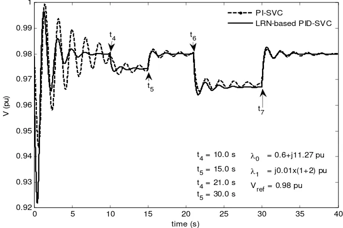
b. Power systems disturbed by additional load at j0.02 pu
Figure 10 and Table 2 show the simulation results of power systems. Additional load atj0.01 pu was forced at time t4(10 s).In this operation the network was deficit of reactive power
then the voltage magnitude was decreased until t5 (15 s).
In order to increase the load voltage to the setting value, it was needed to switch on the SVC device at t5.The reactive power was injected from SVC to the network at the value of
j0.0166 pu. By using this reactive power then the voltage magnitude was increased to the setting value until t6 (21 s).Next, the additional load at j0.02 pu was forced at time t6, at this
moment the load voltage decreased to the value of 0.9671 pu until t7 (30 s). And, the SVC
susceptance (Bsvc)and reactive power injected from SVC to networks (Qsvc)were increased to the
values of j0.0396pu and j0.0380 pu, respectively.In this operation, the SVC supplied the additional voltage to the network (V) at the value of 1.3431103 pu.Finally, the load voltage (
V) was able to increase at the value of 0.980047 pu. The increased of load forced to power systems so that the SVC susceptance, SVC reactive power supplied and SVC additional voltage also increased.
PI-SVC and LRN-based PID-SVC (proposed controller) responses were compared in Figure 10. It is shown that the PI-SVC response was more oscillated than the proposed controller. Meanwhile, the proposed controller gave settling time more rapid than the PI-SVC controller. Moreover, the proposed controller givesbetter response than the PI-SVC controller.
c. Power systems disturbed by additional load at j0.03 pu
The power systems equipped by the controller weretested using larger additional loadsat the values of j0.01, j0.02 and j0.03 pu. Simulation results are shown in Figure 11 and listed in Table 2. At first time, the power systems were operated in an initial load at 0.6+j11.27 pu. The responses of both controllers are shown in Figure 11 in interval 0-t4 (10 s).The
additional load j0.01 was forced to load bus and the voltage magnitude was decreased until t5
(15 s).At t5, the SVC was switched on. Therefore, the SVC supplied reactive power to network
and the voltage magnitude was increased to around the setting value until t6(20 s).The
additional load at j0.02 pu was forced to the load bus at t6 and the voltage magnitude decreased
immediatelyto 0.9671 pu. In order to increase the voltage magnitude toaround the setting value (0.98 pu) again, the SVC susceptance (Bsvc) must be increased at the value of j0.0396 pu at t7(28.0 s). And, the reactive power supplied by the SVC to the network (Qsvc)increased alsoat the
value ofj0.0380 pu. The voltage magnitude (V) stayed at around the setting value until t8 (35 s).
Next, a larger additional load at j0.03 pu was forced to the load bus at t8and the voltage
magnitude decreased to a lower value (0.9573 pu) until t9 (49 s). Finally, the SVC susceptance
was increased to the value of j0.0733 pu at time t9, and reactive power support from the SVC to
the network increasedalso at the value of j0.0700 pu. In this operation, the SVC produced additional voltage (V) at 2.4828103 pu in order to support the load voltage (
V) achieved the setting value at 0.980033 pu.
According to results in Table 2, it is shown that the additional load was increased so that the SVC susceptance, reactive power supplied from the SVC and SVC addtional voltage should be increased in order to maintan the voltage magnitude stayed around the setting value. Meanwhile, from Figure 11 we can see that voltage magnitude response of PI-SVC is more oscillated than the voltagemagnitude response of the proposed controler. And, the voltage magnitude response of PI-SVC is more dificult to achieve equilibrium point than the response of the proposed controller. From these responses it is shown that the performace of the proposed controller is better than the PI-SVC.
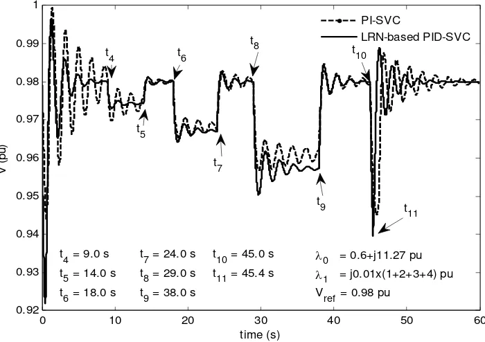
d. Power systems disturbed by additional load at j0.04 pu
Furthermore,power systems equipped by controller were forced by additional load at the values of j0.01, j0.02, j0.03 and j0.04 pu.The voltage magnitude (V) response is shown in Figure 12 and complete results of simulation are listed in Table.At first time, the additional load j0.01 pu was forced to load bus at time t4 (9 s)and the voltage magnitude was decreased to the value of
0.9743 pu until time t5 (14 s).
Next, at time t5 the SVC was switched on and connected to the network. The SVC
susceptance was existed at the value of j0.0173 pu and the SVC supplied reactive power to the network at the value of j0.0166 pu. The voltage magnitude was increased to around the setting value,due to reactive power support from the SVC until t6 (18 s). Next, the additional load (j0.02
pu) was forced at load bus at time t6 and voltage magnitude was decreased and stayed until t7
Figure 11. Responses of both controllers when the loads at j0.01(1+2+3)pu were forced to load bus, then the SVC was switched on and increased the SVC susceptance.
Figure 12. Dynamical Responses of both controllers when the loads at j0.01(1+2+3+4)pu were forced,then the SVC was switched onand increased the SVC susceptance.
At time t8,the additional load (j0.03 pu) was forced to load bus.And, the voltage magnitude was
decreased again due to dificit of reactive power in the networkuntil time t9 (35 s). Next, at t9the
SVC susceptance was increased to support reactive power to the network and the voltage
magnitude increased to the setting value until time t10 (35 s). The maximum additional load at
the value of j0.04 pu was forced to the load bus at t10and the voltage magnitude decreased
immediately to 0.9427 pu. Finally, the SVCsusceptance was increased to the value of j0.1183 pu at time t11 (45.4 s).At this SVC susceptance, the SVC supplied reactive power to the network
at the value of j0.1127 pu. The additional voltage from the SVC to networks (V) and the voltage magnitude were at the values of 4.0095103and 0.980010 pu, respectively.
5. Conclusion
The grown up of load demand on power systems was rapidly. Meanwhile, power plant and transmission line being built was slow due to economical and environmental constraint. This condition makes the existingpower systems were operated onheavyloading near the limit of stability. When power systems are operating near the limit of stability that makes the nonlinear phenomena appearingin power systems such as chaos and voltage collapse. Therefore, LRN-based PID-SVC is proposed to control chaos and voltage collapse in power systems.LRN-based PID is used to suppress chaos and voltage collapse. Meanwhile, LRN-systems.LRN-based SVC is used to regulate and maintain the load voltage. Simulation results show that the proposed controller is able to control chaos and voltage collapse. Moreover, the proposed controller is able to maintain the voltage magnitude at the setting value by controlling the SVC susceptance.The maximum loadingthat can be coveredhandled by the proposed controller isj0.04 pu. And,the SVC susceptance is obtained at the value of j0.1183 pu. In this operation, the SVC supplied the reactive power to the network and the SVC additional voltageare obtained at the values ofj0.1127 and 4.0095103 pu, respectively.Furthermore, voltage magnitude responseof the proposed controller is better than voltage magnitude response of the PI-SVC controller.
References
[1] Chiang HD, Dobson I, Thomas RJ. On Voltage Collapse in Electric Power Systems, IEEE
Transactions on Power Systems. 1990; 5(2): 601-611.
[2] Ajjarapu V, Lee B. Bifurcation Theory and Its Application to Nonlinear Dynamical Phenomena in an Electrical Power System. IEEE Transactions on Power Systems. 1992; 7(1): 424-431.
[3] Chiang HD, Liu CW. Varaiya PP, Wu FF, Lauby MG. Chaos in a Simple Power System. IEEE
Transactions on Power Systems; 1993; 8(4): 1407-1417.
[4] Wang HO. Control of Bifurcation and Routes to Chaos in Dynamical System. PhD Thesis. University of Maryland; 1993.
[5] Wang HO, Abed EH, Hamdan AMA. Bifurcations, Chaos, and Crises in Voltage Collapse of a Model Power System. IEEE Transactions on Circuits and Systems 1: Fundamental Theory and Applications. 1994; 41(3): 294-302.
[6] Ginarsa IM, Soeprijanto A, Purnomo MH. Implementasi Model Klasik untuk Identifikasi Chaotic dalam Sistem Tenaga Listrik Akibat Gangguan Energi. Seminar on Intellegent Technology and Its Applications (SITIA). Surabaya. 2008: 508-513.
[7] Ginarsa IM, Soeprijanto A, Purnomo MH. Modelling of Chaotic Behavior in Power Systems Using Recurrent Neural Networks. International Conference on Advanced Computational Intelligence and Its Application (ICACIA). Jakarta. 2008: 51-56.
[8] Subramanian DP, Devi RPK, Saravanaselvan R. A new algorithm for analysis of SVC’s impact on bifurcation chaos and voltage collapse in power systems. International Journal of Electrical Power and Energy Systems. 2011; 33(5): 1194-1202,
[9] Ginarsa IM, Soeprijanto A, Purnomo MH. Controlling chaos and Voltage Collapse using an ANFIS-based Composite Controller-Static Var Compensator in Power Systems. International Journal of Electrical Power and Energy Systems. 2013; 46: 79-88.
[10] Ginarsa IM, Soeprijanto A, Purnomo MH, Syafaruddin, Hiyama T. Improvement of Transient Voltage Responses using an Additional PID-loop on an ANFIS-based Composite Controller-SVC (CC-SVC) to Control Chaos and Voltage Collapse in Power Systems. IEEJ Transactions on Power and Energy
(Section B). 2011; 131(10): 836-848.
[11] Narendra KS, Mukhopadhyay S. Adaptive Control Using Neural Networks and Approximate Models.
IEEE Transactions on Neural Networks. 1997; 8(3): 475-485.
[12] Levin AU, Narendra KS. Control of Nonlinear Dynamical Systems Using Neural NetworksPart II: Observability, Identification and Control. IEEE Transactions on Neural Networks.1996; 7(1): 30-42. [13] Narendra KS, Parthasarathy K. Identification and Control of Dynamical Systems Using Neural
[14] Harikrishna D, Srikanth NV. Dynamic stability enhancenment of power systems using neural-network controlled static-compensator. Telkomnika. 2012; 10(1): 9-16.
[15] Aribowo W. Stabilisator sistem tenaga listrik berbasis jaringan syaraf tiruan berulang untuk sistem mesin tunggal. Telkomnika. 2010; 8(10): 65-72.
[16] Kundur P. Power System Stability and Control. EPRI. New York: McGraw-Hill. 1994.
[17] Mukherjee V, Ghoshal SP. Intelligent Particle Swarm Optimized Fuzzy PID Controller for AVR System. Electric Power Systems Research. 2008; 77(12): 1689-1698.
[18] Zhang XP, Rehtanz C, Pal B. Flexible AC Transmission Systems: Modelilng and Control. Berlin: Springer-Verlag. 2006.