CERAMICS
INTERNATIONAL
Ceramics International 41 (2015) 12038–12044
Study of the effect of mechanical impact parameters on an impact-mode
piezoelectric ceramic power generator
Amat Amir Basari
a,n, Sosuke Awaji
a, Shintaro Sakamoto
a, Seiji Hashimoto
a, Bunji Homma
b,
Kenji Suto
b, Hiroaki Okada
b, Hideki Okuno
b, Kojiro Kobayashi
b, Shunji Kumagai
ba
Division of Electronics and Informatics, School of Science and Technology, Gunma University, Kiryu-shi, Gunma, Japan
b
Research and Development Department, Mitsuba Corporation, Hirosawa-cho, Kiryu-shi, Gunma, Japan
Received 19 March 2015; received in revised form 19 May 2015; accepted 3 June 2015 Available online 12 June 2015
Abstract
This paper presents an analytical and experimental study on the effect of mechanical impact parameters on impact-mode piezoelectric ceramic power generators. The parameters are the velocity and mass. The method of analysis is based on a weight drop experiment. The results show that the peak of the instantaneous output voltage is proportional to the impact velocity, and for the output power, it is in a straight line relationship with the same parameter. For the same velocity of impact, the advantage of using heavy objects is clear because its momentum and the impact force are higher. However, an adjustment in the velocity of impact is found to be more effective for higher instantaneous output power than the mass. Thisfinding is supported by the output power that is generated by a 4-g steel ball with a momentum of 4.34 g/s, which is almost 300% higher than that of an 8-g steel ball for the same momentum. The frequency responses of a vibration-based impact-mode piezoelectric ceramic power generator also support the same conclusion.
&2015 Elsevier Ltd and Techna Group S.r.l. All rights reserved.
Keywords:Piezoelectric ceramic power generator; Impact mode
1. Introduction
Research achievements in mechanical vibration energy harvesting have been reported widely for decades. The objectives of the research are mostly to propose new designs and to evaluate factors that affect the optimum output power generation. In general, mechanical vibration is converted to electrical energy by using three types of devices: piezoelectric,
electrostatic and electromagnetic. Both analytical [1] and
experimental analyses[2–5]have shown that there are various
factors that affect the performance of the devices. The evaluation of each factor is very subjective; the outcome depends on the devices, environment and type of vibration.
In cases of vibration energy harvesting with piezoelectric ceramics, for a linear motion of vibration, the basic operation of power generation can be divided into two modes. One mode is the bending mode, and the other mode is the impact mode. Usually, for bending-mode power generation with a piezo-electric cantilever beam, one end of the beams will be attached to the vibration sources, and the other end will freely vibrate according to the sources of the vibration. To improve the output power of the piezoelectric power generator in the bending mode, the shape of the device has been analyzed, and it is proven that a device with a triangular shape can more effectively generate electricity compared with the
rectangular-shaped devices[6,7].
Another factor that was found to be important for the optimum
output is the usage of matching impedance as the load [8,9].
However, the matching impedance is dependent on the resonant frequency of the structure, which means that for a low resonant frequency of a structure, large matching impedance is required. www.elsevier.com/locate/ceramint
http://dx.doi.org/10.1016/j.ceramint.2015.06.018
0272-8842/&2015 Elsevier Ltd and Techna Group S.r.l. All rights reserved.
n
Corresponding author. Tel.:þ8180 9774 1081; fax:þ81 277 30 1741.
E-mail addresses:[email protected](A.A. Basari),
These are among the important factors that have been considered in the design of vibration-based bending-mode piezoelectric power generator.
In case of vibration-based impact-mode power generation, piezoelectric ceramics will not deform by the vibration. The
deformation is due to the impact. As reported in [10], a
structure with a freely moving steel ball in a case hits the piezoelectric wall repeatedly to generate electricity. At the beginning of the design process, a weight drop experiment is conducted. The output power from the free-fall experiment is found to be relatively high when compared to the output power of the designated device. One of the suggestions that has been proposed for the optimization of the output power is that the size of the steel ball must be large and heavy. Another design for an impact-mode piezoelectric power generator is reported
by [11]. An impact-mode power generator that consists of a
vibrating beam with a piezoelectric device on top of it and two other piezoelectric cantilever beams placed at each side of the beam is proposed. The vibrating beam has an extended
rectangular tip, and a mass is fixed on it. When the beam
vibrates, it hits both piezoelectric beams and, due to the impact, electricity is generated. The implementation target of the device is to harvest low frequency vibrations such as human motion-related environments. The optimization proce-dure is based on the matching impedance technique. Other analyses and discussion on the combination of bending and
impact-mode power generation is reported in [12]. It is
reported that in terms of the voltage, a bending-mode piezo-electric specimen generates a higher value than that of the impact-mode piezoelectric specimen. However, how the output can be optimized for the designated device was not discussed. There are research studies on the effect of piezoelectric
ceramic dimensions [13] and types of vibrations [14] on
impact-mode piezoelectric power generation. However, the effect of mechanical impact parameters on impact-mode piezoelectric ceramic power generation has been discussed less by researchers. Therefore, this paper presents an analytical and experimental study on how to optimize the output power of an impact-mode piezoelectric power generator by analyzing two parameters that have been found to closely affect the output power. These parameters are the velocity of the impact and the mass. To identify the relationship of the output power with these two parameters, a weight drop experiment was conducted. Variations in the mass of the object and the heights that were related to the impact velocity were performed. The findings can be utilized in the design of an impact-mode piezoelectric power generator to harvest vibration energy in the vehicle systems and industry, which found to produce a large amount of vibrations.
2. Impact force of the weight drop in free fall
When an object is dropped from a certain height, it will give an impact force to the surface of the ground. A change in the energy also occurs where the potential energy of the object turns into kinetic energy upon impact. Let us assume that the
mass of an object ism, the height ish1and the velocity upon
impact is v. Therefore, the energy equation will become
mgh1¼1
2mv
2
ð1Þ
where g is the acceleration of gravity. If the height h1 is
known, then the velocity of the impact would become v¼ ffiffiffiffiffiffiffiffiffiffi
2gh1
p
. Based on the characteristics of the ground and the object, two situations can be expected to occur when an
object is dropped. The first situation is that the object will
penetrate the ground surface. This situation will occur if the ground surface is softer than the dropped object. Let us say that
the penetration ish2before the object totally stops. In this case,
the impact force from the object is denoted by following equation:
F¼Ek
h2 ¼
mv2
2h2 ð2Þ
whereEkis the kinetic energy. As seen from the equation, the
impact force is inversely proportional to the penetration
distance h2, which means that less penetration will result in a
higher impact force.
The second situation that can be expected is that the object bounces back after striking the ground. This situation will occur if the ground surface is harder than the object. A greater change in the momentum from this situation leads to a greater
impact force F. The object is expected to bounce back a few
times until its momentum becomes zero. Another fact that can be seen from this equation is that a small change in the velocity affects the impact force more than a change in the mass. This arrangement occurs because the velocity is proportional to the
F in the square function, while the mass is directly
propor-tional to the impact force. Based on this relationship, it is expected that the output power of a piezoelectric power generator will be more dependent on the impact velocity than the mass of the object if their momentum or kinetic energy is equal.
3. Piezoelectric ceramic power generation by impact
Impact-mode piezoelectric ceramic power generation is an alternative to the vibration bending-mode power generation. In contrast to the bending mode, power generation by impact produces a discontinuous output. An instantaneous output will not last long. The frequency of the repetitive output is dependent on the frequency of the impact.
The maximum electrical energy per cycle output of a piezoelectric power generator in 33-mode is denoted by following equation:
Emax¼ c
abd33g33F
2
ð3Þ
where a, b and c are the width, length and thickness of the
piezoelectric ceramic, respectively, and d33 and g33 are the
piezoelectric charge (strain) and voltage (stress) constants;Fis
where the poling and applied force are in the same direction. From the equation, the effect of the piezoelectric constant is almost unchanged unless there is a change in the stiffness of the piezoelectric properties. Thus, besides the size of the devices, the external factors that effect the maximum energy
generation include only the forceF. For the fundamental study
of impact-mode power generation, the weight drop experiment can be used. The relationship between the force of the dropped object, velocity and mass to the output of impact-mode piezoelectric power generation can be shown from the experiment.
4. Weight drop experiment for impact-mode power generation
The experimental configuration is shown inFig. 1, and the
piezoelectric ceramic specification is shown in Table 1. The
steel balls used in this experiment have two sizes. They are 9.52 mm and 12.7 mm in diameter, with a weight of 4 g and 8 g, respectively. The material of the steel ball is carbon. The piezoelectric ceramic is placed on two types of iron base. One
type isflat and the other has a hole. The diameter of the hole is
30 mm. The size of the hole is sufficiently large to allow the piezoelectric to be free from being supported by the base. The purpose of having two types of supporting base is to evaluate the output power when there is a change in the stiffness of the device. The experiment method is to drop the steel ball in free fall from a predetermined height in such a way that it will strike the piezoelectric ceramic. The output of the piezoelectric power generator is connected to the load resistor, and the reading of the voltage is recorded in a data logger with a
sampling time of 10μs. Three values of the resistor were used
as a load; they are 1 kΩ, 10 kΩand 20 kΩ resistors.
4.1. Experimental results and discussion
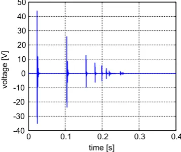
The experiment was conducted with a variation in the height of the steel ball of 10 mm to 70 mm. Each time that the steel ball was dropped, the piezoelectric ceramic would produce a
pulse signal, as seen inFig. 2. This signal is the voltage drop
across the load resistor. Thefirst pulse is the voltage drop of
the load when the steel ball strikes the piezoelectric ceramic.
The next pulse after thefirst strike of the ball is the pulse of the
voltage drop when the steel ball rebounds back and strikes the piezoelectric ceramic again until the momentum of the ball becomes zero. For evaluation purposes, only the peak of the first pulse will be considered and compared.
Figs. 3–6 show the plot of the instantaneous peak output voltage and power versus the height and velocity of the impact
when a steel ball of 4 g and flat base were used as the
experimental conditions. The relationship between the voltage
and height can clearly be seen inFig. 3, which shows that the
voltage is proportional to the square root of the height regardless of the load values. Because a higher load will lead
to a higher voltage, the 20 kΩcurve is always at the top of the
other curves. In the case of voltage against velocity, as denoted
by equationv¼ ffiffiffiffiffiffiffiffiffiffi
2gh1
p
, where the velocity is proportional to the square root of the height, theoretically, the voltage should be directly proportional to the velocity. This relationship can
be seen inFig. 4.
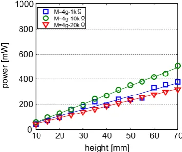
Next, in terms of the power, Fig. 5 shows a peak of the
instantaneous power against the height. It is obvious that the
power is directly proportional to the height. BecausePpV2
and vppffiffiffiffiffih1, the proportionality of the two variables is acceptable. In the case of the power versus velocity, the
Ppv2 relationship is perfect. This result has shown that the
electrical output power of the piezoelectric ceramic will increase with the quadratic function of the impact velocity. In terms of the maximum power density of the piezoelectric
ceramic, with a 10 kΩ load resistor and an impact velocity of
1.17 ms 1, a 61.33 mW/mm3of power can be achieved. From
Figs. 5 and 6, it can be observed that the maximum output
power is achieved with a 10-kΩresistor.
For comparison purposes and to see the effect of the mass on the output power, a steel ball of 8 g was also used in the
Fig. 1. Experimental configuration of the (a)flat setting base and (b) setting base with hole.
Table 1
Specification for the round shape piezoelectric ceramic.
Parameter Value
Diameter of the brass plate 35.070.1 mm
Diameter of the ceramic element 25.070.4 mm
Thickness of the ceramic element 0.2170.05 mm
Young's modulus 5.61010N/m2
Piezoelectric strain constant,d33 42010 12m/V
0 0.1 0.2 0.3 0.4
experiment. The results show that the proportionality of the voltage, power, height and velocity of the 8-g steel ball output is the same as what we can see in the case of the 4-g steel ball. However, the output power of the 8-g steel ball compared to that of the 4-g steel ball is higher when their velocity of impact
is the same. This comparison is shown inFig. 7. This figure
shows the peak instantaneous output power of the balls when
they were dropped from the same height, which means that their velocity of impact is the same.
As seen, at a low velocity, the difference is not significant, but as the velocity increases, the differences in the outputs become clearer. This difference can be explained if the momentum of the ball is considered. The momentum of the 8-g ball is always twice that of the 4-g ball when their velocities are the same. A high value in the momentum contributes to high levels of impact force for the ball. Due to this relationship, the amount of deformation of the piezo-electric ceramic will become relatively high. Subsequently, more output power can be expected with a high momentum
impact, as illustrated in thefigure.
Another result of the power against the momentum of the
balls is shown inFig. 8. Thisfigure compares the output power
when the momentum of the balls is at the same value. The output power for the same momentum is highlighted in this figure. It obviously can be observed that the output power of the 4 g is higher when their momentum is the same. For the same momentum value, the velocity of the 4-g steel ball is always double that of the 8-g steel ball. Therefore, with this result, it is clear that the velocity of impact affects the output power significantly compared with the mass.
4.2. Optimization of the output power
In the previous section, experiments were conducted with
piezoelectric ceramics that were set on a flat iron base. This
arrangement has indirectly increased the stiffness, i.e., Young's modulus of the ceramic structure as a whole. An increment in the stiffness in turn decreased the strain that can be developed on the piezoelectric ceramic and results in lower output power. Therefore, to optimize the output power of the piezoelectric ceramic, a base with a round shape hole was used as a
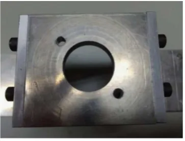
substitute for the flat iron base.Fig. 9 shows the base with a
hole. The diameter of the hole is 30 mm. A piezoelectric ceramic was placed on the base with an appropriate adjustment in such a way that piezoelectric ceramic is placed exactly on the hole.
Experiments were performed with the same weight drop experimental conditions, with variations in the height and the 10 20 30 40 50 60 70
Fig. 3. Instantaneous peak output voltage versus the height.
0.4 0.6 0.8 1 1.2
Fig. 4. Instantaneous peak output voltage versus the velocity.
10 20 30 40 50 60 70
Fig. 5. Instantaneous peak output power versus the height.
0.4 0.6 0.8 1 1.2
steel ball. The output power comparison is shown inFig. 10. In this Fig. 4 data plots are shown. Obviously, no significant different can be observed for the output power of a 4-g steel ball when two different types of bases were used. However, when the steel ball mass was increased to 8 g, the output power of the same momentum of impact has shown an increment for the base with the hole. At the highest momentum of 9.37 g/s, the difference in the output power has become at least
200 mW. This result has shown that increments in the stiffness of the whole structure of the piezoelectric ceramic will reduce the efficiency of the device. Thus, the stiffness of the
piezo-electric ceramic must be considered as well as when efficiency
optimization is required.
5. Forced vibration-based impact-mode piezoelectric ceramic power generator
This section evaluates the piezoelectric ceramic application in power generation when it operates in impact mode. The
structure of the power generator is shown inFig. 11; it consists
of a base beam, a vibrating beam with tip and proof mass and the adjustable spacer. Details of the structures' dimensions are
shown inTable 2. The thickness of the base beam was decided
to be 10 times thicker than the vibrating beam, to prevent its free end from simultaneously deflecting from the vibrating
beam. As shown inFig. 11, the piezoelectric ceramic is bonded
on the base beam, and as the vibrating beam vibrates vertically, the tip will hit the piezoelectric ceramic, and the voltage output across the load resistor, which is connected to the piezoelectric,
0.4 0.6 0.8 1 1.2
0 200 400 600 800 1000
velocity [m/s]
po
we
r [
m
W
]
M=4g-10k M=8g-10k
Fig. 7. Instantaneous peak output power versus the velocity– 4 g and 8 g
steel ball.
Fig. 8. Instantaneous peak output power versus the momentum–4 g and 8 g
steel ball.
Fig. 9. Iron base with a hole.
Fig. 10. Instantaneous peak output power versus the momentum–4 g and 8 g
steel ball output comparison for theflat base and the base with a hole.
will be recorded in the PC. The input signal to the vibrator is
denoted by Eq.(4). To evaluate the output power of the power
generator in the frequency domain, the input signal frequency of the vibrator was varied accordingly. It is noted here that changes in the frequency results in changes in the acceleration of the input vibration.
y tð Þ ¼A cosð Þωt ð4Þ
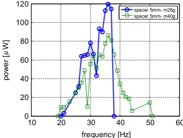
Figs. 12and13show the results of the average output power for 5 ms of time for the power generator when the spacer thickness is 5 mm and 4 mm. It is important to note that when the spacer thickness is 5 mm, the gap between the tip and the surface of the piezoelectric ceramic is 0.604 mm. Therefore, the output power of the power generator can only be obtained if the tip's displacement is larger than the gap, to enable it to hit
the piezoelectric ceramic. As seen inFig. 12, the bandwidth of
the output power of the configuration with a mass of 26 g is approximately 20 Hz, while for the configuration with 40 g of mass, the bandwidth can go up to 30 Hz. Here, an increment in the mass has increased the displacement of the tip and, therefore, a wider output power is obtained. In terms of the magnitude, it can be observed that the configuration with a lighter proof mass produced a higher maximum output by 1.5 times. As was discussed in the previous section, for the same momentum of impact, the configuration that had the higher velocity produced a higher output power. It is predicted that a proof mass of 26 g generated a higher impact velocity than that of the heavier mass. Another important point to be highlighted here is a drop in the output that occurred at the frequency of approximately 30 Hz. As described in the previous section, the power generator is composed of a base beam and a vibrating beam that coupled at one end and free at the other end. As the frequency varies, the amplitude of both beams will also vary. Subsequently, the point of impact also varies accordingly. The velocity of impact is dependent on the point of these impacts. This situation eventually produces anti-resonance and reso-nance output. Due to this reason, even though a clear
resonance output in Fig. 12 is not seen, an anti-resonance
output is clearly illustrated by both plots at this frequency. At this point, the impact was expected to occur at relatively lower velocity than that of the other points.
For the result inFig. 13, the spacer thickness that was used
was 4 mm. Due to the effect of the proof mass, at the initial state, the piezoelectric ceramic is in the pre-load condition. This arrangement can explain the reason why a wider operat-ing frequency bandwidth can be observed in this plot. A small displacement of the vibrating beam can still produce load
forces and hit the piezoelectric ceramic. However, for the configuration that has the heavier proof mass, the bandwidth of the output power is narrower than that of the previous setup. While in the pre-load condition, a heavier proof mass has caused the vibrating beam to become harder, and therefore, it limits the movement of the vibrating beam itself. Thus, as it reaches a higher frequency, the movement of the vibrating beam has stopped and has limited the frequency bandwidth of the power generator. Two resonance output at the frequency of approximately 60 Hz and 85 Hz of the configuration with the
proof mass of 26 g can be observed in this figure.
In terms of the magnitude, a configuration with a spacer thickness of 5 mm appears to be higher than the other configuration. Again, a factor of the impact velocity contri-butes to this result, where it is clear that a freely vibrating
beam in the first configuration will have a higher maximum
impact velocity.
6. Conclusions
Analytical and experimental evaluations of the effect of the velocity of the impact and mass of the object in impact-mode piezoelectric power generation has been presented. Usually, the experimental results show that in the impact-mode piezo-electric power generation, the momentum of an object with a
Table 2
Details of the structures.
Structure Value
Base beam (Aluminum) 1305010 mm
Vibrating beam (Aluminum) 100201 mm
Adjustable spacer (Aluminum) 26201 mm
Proof mass (Aluminum) 26 and 40 g
Tip (Iron) height: 3 mm
Φ: 4.5 mm
Fig. 12. Frequency response–output power for the configuration with a 5-mm
spacer thickness.
Fig. 13. Frequency response–output power for the configuration with a 4-mm
higher impact velocity generates a higher peak instantaneous output power than an object that has the same momentum but
is heavier. This finding was then further analyzed with the
forced vibration-based impact-mode piezoelectric ceramic power generator model. A higher output power was obtained when the vibrating beam was allowed to be vibrated with a larger displacement, which eventually increased its impact velocity. However, this arrangement has caused the operating frequency bandwidth to become narrower.
Acknowledgments
The corresponding author appreciates the Government of Malaysia and the Faculty of Electronics & Computer Engineering
of UTeM forfinancial support during his PHD study at Gunma
University (KPT(BS)770524086441).
References
[1] Z. Chen, B. Guo, Y. Luo, Y. Yang, Numerical investigations into the effects of multiple parameters on nonlinear piezoelectric vibration energy harvesters, Adv. Mech. Eng. 2014 (2014) 9.
[2] S.M. Chen, J.H. Hu, Experimental study of a hybrid vibration energy harvesting mechanism, in: Proceedings of the 2011 Piezoelectricity, Acoustic Waves and Device Applications (SPAWDA) Symposium, (2011), pp. 56–59.
[3] Z. Wang, B. Wang, M. Wang, H. Zhang, W. Huang, Model and experimental study of permanent magnet vibration-to-electrical power generator, IEEE Trans. Appl. Supercond. 20 (3) (2010) 1110–1113.
[4] Y. Sang, X. Huang, H. Liu, Ping Jin, A vibration-based hybrid energy harvester for wireless sensor systems, IEEE Trans. Magn. 48 (11) (2012) 4495–4498.
[5]L. Yan, J. Hou, Z. Yang, X. Chu, Design and experimental characteriza-tion of a vibracharacteriza-tion energy harvesting device for rotacharacteriza-tional systems, Adv. Mech. Eng. 2013 (2013) 7.
[6] A. Shebeeb, H. Salleh, Effect of cantilever shape on the power output of a piezoelectric bimorph generator, in: Proceedings of the Semiconductor Electronics International Conference, (2010), pp. 275–278.
[7]A.A. Basari, S. Awaji, S. Wang, S. Hashimoto, S. Kumagai, K. Suto, H. Okada, H. Okuno, B. Homma, W. Jiang, S. Wang, Shape effect of piezoelectric energy harvester on vibration power generation, J. Power Energy Eng. 2 (9) (2014) 117–124.
[8] A.A. Basari, S. Awaji, Y. Zhang, S. Wang, S. Hashimoto, S. Kumagai, M. Kasai, K. Suto, W. Jiang, S. Wang, Comparison and evaluation of vibration-based piezoelectric power generators, in: Proceedings of the International Power Electronics Conference, (2014), pp. 3194–3199.
[9]N. Kong, D.S. Ha, A. Erturk, D.J. Inman, Resistive impedance matching circuit for piezoelectric energy harvesting, J. Intell. Mater. Syst Struct. 0 (2010) 10.
[10] E. Simon, Y. Hamate, S. Nagasawa, H. Kuwano. 3D Vibration harvesting using free moving ball in PZT microbox, in: Proceedings of the Power MEMS, (2010), pp. 33–36.
[11] M.A. Halim, K. Sungwon, J.Y. Park, Impact based frequency increased piezoelectric vibration energy harvester for human motion related environments, in: Proceedings of the 8th IEEE International Nano/Micro Engineered and Molecular Systems Conference, (2013), pp. 949–952.
[12] M. Han, Y.C. Chan, W. Liu, S. Zhang, H. Zhang, Low frequency PVDF piezoelectric energy harvester with combined d31 and d33 operating modes, in: Proceedings of the 8th IEEE International Nano/Micro Engineered and Molecular Systems Conference, (2013), pp. 440–443.
[13]X.R. Chen, T.Q. Yang, W. Wang, X. Yao, Vibration energy harvesting with a clamped piezoelectric circular diaphragm, Ceram. Int. 38S (2012) 271–274.