UNIVERSITI TEKNIKAL MALAYSIA MELAKA
AUTOMATED FACTORY SAFETY CONTROL SYSTEM USING
PLC
This report submitted in accordance with requirement of the Universiti Teknikal
Malaysia Melaka (UTeM) for the Bachelor Degree of Manufacturing Engineering
(Robotic and Automation) with Honours.
by
MOHD SYUKRI BIN MOHAMED
FACULTY OF MANUFACTURING ENGINEERING
DECLARATION
I hereby, declared this report entitled “Automated Factory Safety Control System Using PLC” is the results of own my research except as cited in references.
Signature:
APPROVAL
This report is submitted to the Faculty of Manufacturing Engineering of UTeM as a
partial fulfillment of the requirements for the degree of Bachelor of Manufacturing
Engineering (Robotic and Automation) with Honours. The member of supervisor
committee is as follow:
(Signature of Supervisor)
ABSTRAK
Kajian in dilakukan untuk mencari dan mengenalpasti permasalahan yang di hadapi di
dalam industri. Pendekatan ini dilakukan bagi menambahbaik sistem yang ada sekarang
dengan mengunakan sistem yang ringkas dan berkesan. ’ Automated Factory Safety Control’ di lengkapi dengan PLC (Pengawal logik aturcara) yang memainkan peranan sebagai perantara antara penderia dengan paparan LED. Sistem ini beroperasi mengawal
operasi mesin, mengawal suhu di dalam kilang, mengenalpasti kerosakkan dalam sistem
kawalan elektrik dan lain lain lagi. Paparan LED digunakan bagi mengenal pasti
kerosakkan yang di alami. Sistem ini dapat membantu mengurangkn masa lengah mesin,
mengurangkan kos baik pulih mesin dan membantu memudahkan kerja kerja baik pulih
ABSTRACT
This paperwork describe about a problem faces in industrial by improving an existed
system with effective and simple . PLC (programmable logic controller) has been used
acts as a interface between sensor and LED display for this automated factory control.
Operation of this system are control machine, control temperature, and detect fault in
electrical control system. This system can be help to reduce a downtime and cost
DEDICATION
ACKNOWLEDGEMENT
I wish to thank my supervisor, En. Shariman Bin Abdullah for his valuable advice,
constructive criticisms, stimulating discussions and valuable suggestions during the
preparation of this project report. I would like to express my thanks to all colleagues
who are always ready to give their helping hands. Last but not least, no words can be
used to express my deepest gratitude to my parent and family for their encouragement
and love, which are forever indebted.
TABLE OF CONTENTS
2.2.2 Smart (Intelligent) System 9
2.3 Monitoring System 11
2.3.1 The performance of the monitoring system 12
2.3.2 Push Button Panel PP7 and PP17 14
2.3.3 Text Display 15
2.3.4 Graphic Display OP1 70B and OP2 70 16
2.3.5 Touch Panel TP1 70 and TP2 70 16
2.4 Fault Detection 18
2.4.1 Fire Detection System 18
2.4.1.1 Smoke Detection 18
2.4.1.2 Heat Detectors 20
2.4.1.3 Flame Detectors 21
2.4.2 Temperature Sensor 21
2.4.2.1 Type Of Temperature Sensor 22
2.4.2.2 Classes Of Temperature Sensor 23
2.4.2.3 Analog Plus Temperature Sensor 24
2.4.2.4 Temperature Control System Using LM 35 25
2.5 Controller System 27
2.5.1 PLC (Programmable Logic Controller) 27
2.5.1.1 Ladder Logic 32
2.5.1.2 Programming 33
2.5.1.3 PLC Connection 36
2.5.1.4 Ladder Logic Inputs 37
2.5.1.5 Ladder Logic Outputs 38
2.5.2 PIC (Programmable Integrated Circuit) 39
2.5.2.1 PIC Instruction Structure 40
2.6 Summary 42
3. METHODOLOGY
3.1 Introduction 43
3.2 Problem Statement Identified 44
3.3 Project Planning 44
3.3.1 Gantt Chart 45
3.4 Research About Project 46
3.5 Design Factory Model 46
3.6 PLC Ladder Diagram 47
3.8 Analyzing 49
4.2 Electrical and Electronic Construction 55
4.2.1 LED Wiring 56
4.2.2 Relay Wiring 57
4.2.3 DC Motor Speed Controller 59
REFERENCES 90
APPENDIX
A- Ladder Diagram of PLC B- Programming PIC
LIST OF FIGURES
2.1 Simple Automated Cell 5
2.2 Relationship Block Diagram For Argus System 7
2.3 Hard wiring require a large number of control wires to 9
interconnect a system
2.4 A smart device uses a communication protocol that allows 10
individual device to communicate with each other
2.5 Monitor may be added to protect a system from many 13
different type problem
2.6 Series Device 14
2.7 Push Button Panel 15
2.8 Front View Of The TD 17 Text Display 15
2.9 Front View Of The OP170B and OP270 Graphics Display 16
2.10 Front View Of The TP170 and TP270 17
2.11 Front View Of The MP270B and MP370 Multi Panel 17
2.12 Ionization Detector 19
2.13 Photoelectric Detector 20
2.14 Heat Detector 20
2.15 Sensor and IC Manufacturers 23
2.16 ICs that signal when a temperature has been exceeded 25
Are well suited for over/under temperature alarms
2.17 Block Diagram Of Temperature Sensor Using LM32 25
2.18 Power Transistor 26
2.19 Sensor LM 35 26
2.20 The block diagram of the typical component that make up a PLC 27
2.21 SLC processor module (CPU) 28
2.22 a) Status of real world , b) The memory control one output 29
2.23 Various racks sizes 30
2.24 Modules, racks, and a rack filled with modules 30
2.25 PLC direct I/O wiring 31
2.26 Simple Relay layouts and Schematic 32
2.27 A simple relay controller 33
2.28 An Example of a Mnemonic Program and Equivalent Ladder Logic 34
2.29 An Example of a Sequential Function Chart 35
2.30 An Example of a Structured Text Program 36
2.31 The Separation of Controller and Process 36
2.32 The Scan Cycle of a PLC 37
2.33 Ladder Logic Inputs 38
2.34 Ladder Logic Outputs 39
2.35 A typical Microcontroller system 40
2.36 PIC 16C84 and Oscillator Circuit 41
4.1 Top view of indication system and factory model with dimension 53
4.2 Side view of design indication system and factory model. 53
4.3 Font view of design indication system 54
4.5 Design Factory Model 55
4.6 Circuit connection LED with Resistor. 56
4.7 Complete the LED connection. 57
4.8 Symbol for relay 57
4.9 Connection diagram relay 58
4.10 Connection Relay 58
4.11 DC motor speed controller. 59
4.12 motor speed controller. 60
4.13 LDR circuit. 61
4.14 Control circuit extension of solar and LDR 62
4.15 Complete system (solar and LDR) 62
4.16 LED indication of solar system 63
4.17 Servo Motor 63
4.25 Temperature control circuit 68
4.26 Schematic of Smoke detection. 69
4.27 Smoke detection 69
4.28 Smoke sensor 70
4.29 LED indication for smoke system 70
5.1 Circuit Connection 73
5.2 Setup 74
5.3 RS232 Cable and Serial Cable 75
5.4 Operating Mode to Run 75
5.6 Ladder Diagram of Electrical System. 79
5.7 Ladder diagram of solar system. 80
5.8 Ladder diagram of machine status. 81
5.9 Ladder diagram for door lock system 82
5.10 Ladder diagram of master control. 83
5.11 Temperature control system using LM 35. 84
5.12 Design the temperature control circuit. 85
5.13 PIC Command. 86
LIST OF TABLE
4.1 List the DC motor speed controller component. 59
4.2 Component description 60
4.3 List of component 66
5.1 Assigned Input Address and Address Description. 76
CHAPTER 1
INTRODUCTION
1.1 Project Background
Safety systems provide the safety for humans, machines and environment. They are
used to prevent accidents and damage resulting from a fault or malfunction. The
safety controllers (Safety Integrated) detect faults autonomously and immediately
change into or remain in a safe mode when a fault occurs. They are optimized for use
in production engineering and provide air-tight safety for all its many facets.
All industry must include safety protection device to protect the machine, electrical
equipment, operator and to produce the quality of product. All system are required to
have a minimum amount of protection to protect personnel and property. Most
system required more than the required minimum amount of protection in order to
minimize equipment damage and reduce maintenance downtime.
In this project, PLCs have been used to reduce costs and increase productivity. They
are now being incorporated for safety aspects. Safety PLCs are easier to repair and
use while also reducing false alarms
By acting as a automated factory safety control system, when a problem and error
occurs in the system of factory, number, light indicator or words are displayed on a
digital readout attached to the equipment or LED display panel.
1.2 Objective
The main objective of this project is to develop a automated factory safety control
system using PLC. This system can be detect fault of the all system and show in
LED fault indicator. All of the system controlled by PLC (Programmable Logic
Controller) and PIC (Programmable Integrated circuit). Additional objective of this
projects are :
(a) To develop a fully functional controller that can be used to detect the problem in
the system.
(b) To design and develop a program PLC and PIC controller.
(c) To reduce course of maintenance in industry
(d) To design a LED display panel
1.3 Scope Of Work
The scope should be identified and planned to achieve the objective of the project
successfully on the time, first the scope for this project is to design and develop an
electrical circuit to control input and output from PLC (Programmable Logic
Controller). Second scope is to design a program in PLC system for control all or the
system, the design program must be function, easy to understand and comfortable to
maintenance. Another scope are :
1.4 Problem Statement
In most industrial, they still used manual system to control their system. The
malfunction at DB (Distributor Board) occurred when there are no supply current, it
is one of the example of manual system that used in industry. In order to detect the
malfunction manually a multimeter or multitester is used to ensure the component
are damage. Some of the manual procedure that one still being practice in industry
are such as trigger the blower fan, fault machine detection and others. When manual
system fail to operate it will give side effect such as interfering with machine
movement. It will also effect the maintenance occurred thus effecting the production
course. In order to overcome this problem, a automated factory safety control system
with LED display panel is used. It function as a monitoring device to the factory
with only one workstation.
CHAPTER 2
computers to control industrial machinery and processes, replacing human operators.
In the scope of industrialization, it is a step beyond mechanization. Whereas
mechanization provided human operators with machinery to assist them with the
physical requirements of work, automation greatly reduces the need for human
sensory and mental requirements as well. Currently, for manufacturing companies,
the purpose of automation has shifted from increasing productivity and reducing
costs, to broader issues, such as increasing quality and flexibility in the
manufacturing process.
The old focus on using automation simply to increase productivity and reduce costs
was seen to be short-sighted, because it is also necessary to provide a skilled
An automated system is collection of device working together to accomplish tasks or
produce a product or family of product.(John Stenerson (2003)). An automobile, for
example, is an automated system. The automobile has a brain box to receive inputs
from various sensor and to control various output that regulated the engine’s
operation and other function such as antilock braking.
A home burglar alarm system is another automated system. its control box receives
input from sensor and switches located on doors and windows of the house. If the
control box receives a signal that a door or window has been opened, it sound the
alarm and calls the police department. (John Stenerson (2003)
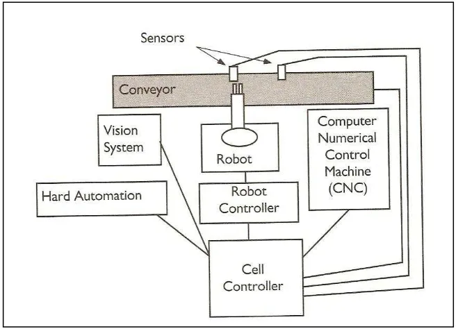
Industrial automated system can be one machine or a group of machines called a cell,
show in figure 2.1 below :
The cell has a conveyor for bringing material into and out of the cell, a robot to move
the material between devices in the cell, a CNC machine for the machining the parts,
a hard automation device for a special task, a vision system for inspecting the parts,
some sensor for sensing parts, and a cell controller for integrating and controlling all
of the other device. Device includes those that actually produce the product and that
provide support, control, and feedback to the system. The four basic type of device in
a cell are production, support, control, and feedback. (John Stenerson (2003).
2.2 Smart Factory
Smart factory its means in industrial the factory used the high safety to protect all
system. Where PLC will control the alarm system and analyse data from sensor. In
smart factory PLC is used to detect temperature gradient, smoke alarm detection,
machine operation and malfunction of electrical system. The PLC will control the
alarm system and analyse data from sensor and show on the indicator controller
monitor.
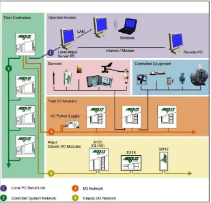
2.2.1 Argus Titan System
In industrial like ‘’Argus Titan System’’, are used automation safety system, The
Argus Titan system is a user-programmable, real-time control system with dedicated
distributable hardware. It has been specifically designed to accomplish three
objectives within a single platform:
(a) Automated equipment control
(b) Monitoring and alarms
Figure 2.2: relationship block diagram for Argus system
For horticulture applications, the Argus system can also meet the needs of the crop
by controlling CO2 levels, irrigation, chemical treatments, and nutrient supplies. It
continuously monitors all growing environments and equipment operations and
reports on the consumption and supply of resources such as water, electricity, heat,
and chemicals and equipment operation hours.
The Argus system not only addresses direct safety problems with proper equipment
installation and wiring, but also includes additional settings to further protect and
improve operation. These include
(a) Minimum “on” and “off” times prevent short-cycling and premature wear of
equipment.
(b) Power-up delay times will delay and stage load operations upon return from
power failures or drop outs. This feature is much appreciated by either your
(c) Event records and data recording provide summaries of equipment operating
frequency and duration as well as a continuous operating audit. This information
is very important when evaluating performance or maintenance and service
requirements.
(d) Multiple operating limits, and safety overrides can be configured to ensure the
safest operation, and extend the operating life of equipment.
(e) Modulating control - the Argus system contains programs to manage modulating
equipment such as hot water heating systems and ventilation systems. These
systems are capable of delivering a wide range of output levels. The computer
can calculate and then directly deliver the correct output, after evaluating a range
of operator set limits
(f) Pulse-width modulation - most on/off equipment is either too effective when on
or not effective enough when off. Unfortunately, most equipment responses
required are somewhere between these two extremes. Staging of multi-unit
systems like cooling fans can provide some intermediate steps, but these are not
sufficient for full smooth control.
(g) The Argus system can cycle a piece of equipment on and off in proportion to the
required response and achieve a very full range of control. The inertia of the
greenhouse environment can absorb these operating pulses quite effectively and
smooth out the “bumps”. For example, the computer will turn a unit heater “off”
after the calculated heat requirement has been delivered, regardless of the current
air temperature. The longer term air temperature average will include the pulse of
heat and future heat pulses will be adjusted to give greater or lesser response as
required. This control strategy greatly reduces temperature overshoot, resulting in
lower energy costs and a better growing environment without increasing the total
number of equipment operations (cycling). It is particularly effective when
managing fog and mist systems.
The distributed network of controllers is treated as a single system. The activities of
individual controllers can be coordinated to accomplish cross-module control
objectives such as irrigation and the efficient distribution of heat from a central
Typical Hardware components include in this smart system is, :
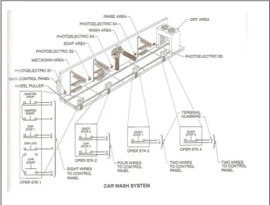
In the hard wiring circuit, inputs such as limit switch, emergency push button, sensor
such as temperature switches are wired into the system using several different wires
for each device. For example is show a car wash system in figure 2.3 below :