International Review on
Modelling and Simulations
(IRE MOS)
Contents:
A Comparative Analysis of THD Simulation in an Asymmetric Cascaded Multilevel Inverter by J. L oranca, J. A guayo, A . Claudio, L . G. V ela, R. A . V argas, J. A rau, M. Rodríguez
1728
An Innovative Isolated Bidirectional Soft-Switched Battery Charger for Plug-In Hybrid E lectric Vehicle
by Seyyedmilad E brahimi, Farid Khazaeli, Farzad Tahami, Hashem Oraee
1739
Performance E valuation of Multicarrier SPWM Techniques
for Single Phase Seven Level Cascaded E mbedded Z-Source Inverter by T. Sengolrajan, B. Shanthi, S. P. Natarajan
1746
Adaptive Neural Network with Heuristic Learning Rule for Series Active Power F ilter by Behzad Ghazanfarpour, Mohd A mran Mohd Radzi, Norman Mariun
1753
Two Stage KY Converter Voltage Ripple Reduction and Load Regulation by Neuro F uzzy Controller
by K. Balaji, S. Karthik umar, K. Suresh Manic
1760
Mitigation of Harmonics in Matrix Converter System Using Anfis Controller by S. Chinnaiya, S. U. Prabha
1766
Islanding Detection Method without Non-Detection Zone
Based on Usage of Single Parameter (ISDE T) Calculated from Voltages by H. L aak sonen
1771
E ffects of Wind Turbine Power Curve in Wind Speed Prediction E rrors by Diogo L . Faria, Rui Castro
1780
Observations on Locational Marginal Price in a Double Auction Deregulated Power System by A runachalam S. A bdullah Khan M.
1787
Improvement of Power Quality in Distribution System Using F uzzy - Unit Vector Controller by T. Guna Sek ar, R. A nita
1794
E valuation of the Sympathetic Interaction between Three 150MVA Power Transformers During E nergizing the Third Transformer in Shahr-e-Kord 400/ 63kV Substation by Behzad Sedaghat, Hamed Mehrvarz, Mehdi Jalali Mashayek hi
1801
A Novel Performance Index for Placement of Distributed Generation in Distribution System by D. Sattianadan, M. Sudhak aran, S. V idyasagar, K. V ijayak umar
1809
(continued on inside back cover)
ISSN 1974-9821 Vol. 6 N. 6 December 2013
PART
A
REPRINT
International Review on Modelling and Simulations
(IREMOS)
Editor-in-Chief:
Santolo Meo
Department of Electrical Engineering FEDERICO II University
21 Claudio - I80125 Naples, Italy santolo@unina.it
Editorial Board:
Marios Angelides (U.K.) Brunel University
M. El Hachemi Benbouzid (France) Univ. of Western Brittany- Electrical Engineering Department Debes Bhattacharyya (New Zealand) Univ. of Auckland – Department of Mechanical Engineering Stjepan Bogdan (Croatia) Univ. of Zagreb - Faculty of Electrical Engineering and Computing Cecati Carlo (Italy) Univ. of L'Aquila - Department of Electrical and Information Engineering Ibrahim Dincer (Canada) Univ. of Ontario Institute of Technology
Giuseppe Gentile (Italy) FEDERICO II Univ., Naples - Dept. of Electrical Engineering Wilhelm Hasselbring (Germany) Univ. of Kiel
Ivan Ivanov (Bulgaria) Technical Univ. of Sofia - Electrical Power Department
Jiin-Yuh Jang (Taiwan) National Cheng-Kung Univ. - Department of Mechanical Engineering Heuy-Dong Kim (Korea) Andong National Univ. - School of Mechanical Engineering
Marta Kurutz (Hungary) Technical Univ. of Budapest
Baoding Liu (China) Tsinghua Univ. - Department of Mathematical Sciences Pascal Lorenz (France) Univ. de Haute Alsace IUT de Colmar
Santolo Meo (Italy) FEDERICO II Univ., Naples - Dept. of Electrical Engineering Josua P. Meyer (South Africa) Univ. of Pretoria - Dept.of Mechanical & Aeronautical Engineering Bijan Mohammadi (France) Institut de Mathématiques et de Modélisation de Montpellier Pradipta Kumar Panigrahi (India) Indian Institute of Technology, Kanpur - Mechanical Engineering Adrian Traian Pleşca (Romania) "Gh. Asachi" Technical University of Iasi
Ľubomír Šooš (Slovak Republic) Slovak Univ. of Technology - Faculty of Mechanical Engineering Lazarus Tenek (Greece) Aristotle Univ. of Thessaloniki
Lixin Tian (China) Jiangsu Univ. - Department of Mathematics Yoshihiro Tomita (Japan) Kobe Univ. - Division of Mechanical Engineering George Tsatsaronis (Germany) Technische Univ. Berlin - Institute for Energy Engineering Ahmed F. Zobaa (U.K.) Brunel University - School of Engineering and Design
The International Review on Modelling and Simulations (IREMOS)is a publication of the Praise Worthy Prize S.r.l.. The Review is published bimonthly, appearing on the last day of February, April, June, August, October, December.
Published and Printed in Italy by Praise Worthy Prize S.r.l., Naples, December 31, 2013.
Copyright © 2013 Praise Worthy Prize S.r.l. - All rights reserved.
This journal and the individual contributions contained in it are protected under copyright by Praise Worthy PrizeS.r.l. and the following terms and conditions apply to their use:
Single photocopies of single articles may be made for personal use as allowed by national copyright laws.
Permission of the Publisher and payment of a fee is required for all other photocopying, including multiple or systematic copying, copying for advertising or promotional purposes, resale and all forms of document delivery. Permission may be sought directly from Praise Worthy Prize S.r.l. at the e-mail address:
administration@praiseworthyprize.com
Permission of the Publisher is required to store or use electronically any material contained in this journal, including any article or part of an article. Except as outlined above, no part of this publication may be reproduced, stored in a retrieval system or transmitted in any form or by any means, electronic, mechanical, photocopying, recording or otherwise, without prior written permission of the Publisher. E-mail address permission request:
administration@praiseworthyprize.com
Responsibility for the contents rests upon the authors and not upon the Praise Worthy PrizeS.r.l..
Statement and opinions expressed in the articles and communications are those of the individual contributors and not the statements and opinions of Praise Worthy PrizeS.r.l.. Praise Worthy PrizeS.r.l. assumes no responsibility or liability for any damage or injury to persons or property arising out of the use of any materials, instructions, methods or ideas contained herein.
Praise Worthy PrizeS.r.l. expressly disclaims any implied warranties of merchantability or fitness for a particular purpose. If expert assistance is required, the service of a competent professional person should be sought.
International Review on Modelling and Simulations (I.RE.MO.S.), Vol. 6, N. 6
ISSN 1974-9821 December 2013
Manuscript received and revised November 2013, accepted December 2013 Copyright © 2013 Praise Worthy Prize S.r.l. - All rights reserved
1899
BLDC Motor Control Using Simulink Matlab and PCI
Bambang Sujanarko
1, Bambang Sri Kaloko
1, Moh. Hasan
2Abstract
– This paper presents the control of BLDC motor using Simulink Matlab and PCI as interfacing to hardware. The control based on six step method that have certain relations among rotor positions and winding currents. These relations convert to digital functions and simplify using K-Map. The result then implemented by basic digital elements on Simulink Matlab and used to trigger the inverter through PCI interfacing to produce six step waveform. Before feed to inverter, a PWM added to these signal as speed control of BLDC motor. Test experiment results show that the control can produce variable speed, voltage and current. Copyright © 2013 Praise Worthy Prize S.r.l. - All rights reserved.Keywords
:
BLDC, Control, Karnaugh, Simulink, PCI, Six Step, PWMNomenclature
B Friction coefficient
Bx Fux density vector
D Duty cycle (Ton/T)
E,Ea, Eb,Ec Back-EMF in winding, in winding A, in
winding B, in winding C
HA, HB, HC Hall A, Hall B, Hall C
I, Ia,Ib, Ic Motor Current in winding, in winding A,
in winding B, in winding C
J Moment of inertia
L,La, Lb,Lc Self inductance in winding, in winding A,
in winding B, in winding C
Lx Length of the core
Np Number of active phases
Nspp Number of slots per pole per phase
Nt Number of turns per slot per phase
Nt Number of turns per slot per phase
P Number of magnet poles
Qn,Q1,Q2,
Q3,D4, Q5, Q6
Inverter switch in n-th, in switch 1, switch 2, switch 3, switch 4, switch 5, switch 6
R,Ra,Rb,Rc Resistance in winding, in winding A, in
winding B, in winding C
Rx Outer radius of rotor (moment arm)
Te Electric Torque
TF Friction Torque
TJ Inertia Tourque
TL Load torque
Vs Voltage supply
Abbreviation
BLDC Brushless Direct Current
CCW Counter Clockwise
CW Clockwise
EMF Electric Motion Force
K-Map Karnaugh Map
PCI Peripheral Component Interconnect
PWM Pulse Width Modulation
I.
Introduction
BLDC motors have many advantages over other types of motors. These advantages are high torque, low maintenance, high efficiency, long life operating, low noise, high density power and high reliability [1].
Due to their properties and the evolution of low-cost power semiconductor switches and permanent magnet materials, BLDC motors are widely used in automotive, robotics, industrial automation equipment, machine tools, medical, instrumentation and so on [1], [2].
In order to produce good performance, BLDC motor require particular control for specific system. Many designs and methods have been created for this purpose. Some of the controls use the Field Programmable Gate Array, Digital Signal Processor, Application Specific Integrated Circuit, and the most is using a microcontroller [3]-[7].
But these controls is not flexible, because it is not possible to change easily, such as exchange PWM frequency, current limitation, type of closed-loop control and others. To solve this problem, this research will be build BLDC motors control using computer, which based on Simulink Matlab and PCI 1711 L interfacing.
This control is expected to gain control system that easily modeled and modified, so that it can be used to obtain the optimal control system, only by changing the software.
This research is a continuation of previous research, which has resulted in digital circuits represent logic functions among the sensor signals to triggers of the inverter [8].
II.
BLDC Control Fundamental
II.1. Basic Structure
Bambang Sujanarko, Bambang Sri Kaloko, Moh. Hasan
Copyright © 2013 Praise Worthy Prize S.r.l. - All rights reserved International Review on Modelling and Simulations, Vol. 6, N. 6 commutation. To realize electronic commutation and
synchronization, A BLDC motor system usually consist of five main parts, power inverter (1), inverter drive (2), logic circuit (3), positions sensor (4) and BLDCmotor (5), as shown at Fig. 1 [1], [8].
C
A B
Q1 Q2 Q3
Q4 Q5 Q6 +V
GND Gate
Q1 Gate
Q2 Gate
Q3 Gate
Q4 Gate
Q5 Gate
Q6 Direction
Speed
(1) (2)
(3)
(4)
BLDC Motor
Copyright: bambang sujanarko
(5)
Fig. 1. Basic block diagram of BLDC motor
The basic principle of a BLDC motor is brief as follows. The position sensor (4), usually Hall sensor or Back EMF detection, will give sign of place mark the permanent magnet against the winding. These sign generally in the three bits data.
The signs then entered in a logic circuit (3) to convert into 6 trigger signals for each switch of inverter (1), which usually composed from power device like MOSFETs or 6 IGBTs. In the logic circuit, the trigger signals also regulate to desire direction and speed of rotation. The result depend on direction signal and the setting of speed. Before enter to the inverter, the trigger signals entered to the driver circuit (2). In this circuit, the signals will be matching to the specification of the switch devices.
Finally, by condition of switch of inverter, an example, the power flow from +V to switch (Q1), winding (C), winding (A), switch (Q5) and Ground.
And then position sensor detect sign of place mark the permanent magnet against the winding again in the different condition, and the process will be return to logic circuit.
II.2. Six Step Commutation
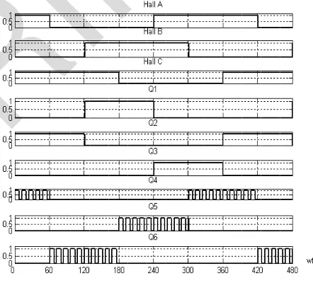
As seen in Fig. 1, BLDC motors using a three phase power inverter that commute sequentially every 60 degrees. These commutations produce six different in one cycle as shown in Fig. 2.
This figure show the waveforms of Back-EMFs (Ea,
Eb, Ec), current (Ia, Ib, Ic) and Hall position sensors (Hall A, Hall B and Hall C) [1]-[8]. Back-EMFs in this figure is the trapezoidal type. Other type of Back-EMFs is Sinusoidal [1]-[7].
Because there are six pattern of commutation, so it called six step commutation. The first commutation occurs in 30o until 90o, the 2th in 90o until 150o, the 3th in 150o until 210o, the 4th in 210o until 270o, the 5th in 270o until 330o and the 6th in 330o until 30o.
Ea
Eb
Ec Ia
Ib
Ic
Hall A
Hall C Hall B
330o 0o
30o 90o 150o210o 270o 30o
1 cycle
wt
wt
wt
wt
wt
wt
Fig. 2. Back-EMFs, current and Hall position sensors waveform of BLDC motor
If the presence of currents in the winding, Hall sensor detection and direction of rotation is converted to a digital logic 1 and 0, then the relationship of these variables can be expressed by Table I [8]. From this table, if the direction is CW rotation, there are six possible of Hall position and in the switch condition of inverter (Q1 to Q6). If the direction is CCW, the possible also in six too.
An example, using Fig. 1, Fig. 2 and line 1 of Table I, if direction is CW that means the digital logic in the Table I is 1, and the Halls (HA, HB and HC) detect value 1 0 1, so the logic circuit produce signal triggers 1 0 0 0 1 0 for Q1 until Q6.
This triggers cause Q1 and Q5 switch on as shown in Fig. 1, and produce current from +V though Q1, the winding C in the positive polarity, the winding B in the negative polarity, and finally though Q5 to flow to GND. Waveform of this example shown in the first commutation that occurs in angle 330o until 30o.
TABLEI
RELATIONSHIP AMONG DIRECTION,THE POSITION
OF HALL SENSOR AND SWITCHING IN THE INVERTER
Dir HC HB HA Q1 Q2 Q3 Q4 Q5 Q6
CW
1 1 0 1 1 0 0 0 1 0
1 1 0 0 0 0 1 0 1 0
1 1 1 0 0 0 1 1 0 0
1 0 1 0 0 1 0 1 0 0
1 0 1 1 0 1 0 0 0 1
1 0 0 1 1 0 0 0 0 1
CCW
0 0 0 1 0 0 1 1 0 0
0 0 1 1 0 0 1 0 1 0
0 0 1 0 1 0 0 0 1 0
0 1 1 0 1 0 0 0 0 1
0 1 0 0 0 1 0 0 0 1
0 1 0 1 0 1 0 1 0 0
Bambang Sujanarko, Bambang Sri Kaloko, Moh. Hasan
Copyright © 2013 Praise Worthy Prize S.r.l. - All rights reserved International Review on Modelling and Simulations, Vol. 6, N. 6
1901
II.3. Logic Simplification with Karnaugh Maps
If Table I convert to digital logic function, Eq. (1) is the general form of this correlation. In this function Qnis
inverter switch n-th, where n is 1 until 6. Eq. (2) up to Eq. (7) show the functions in the single form:
n C B A
Q f Dir,H ,H ,H (1)
1 C B A C B A
C B A C B A
Q DirH H H Dir H H H
Dir H H H DirH H H
(2)
2 C B A C B A
C B A C B A
Q Dir H H H Dir H H H
DirH H H DirH H H
(3)
3 C B A C B A
C B A C B A
Q DirH H H DirH H H
Dir H H H Dir H H H
(4)
4 C B A C B A
C B A C B A
Q DirH H H Dir H H H
Dir H H H DirH H H
(5)
5 C B A C B A
C B A C B A
Q DirH H H DirH H H
Dir H H H Dir H H H
(6)
6 C B A C B A
C B A C B A
Q Dir H H H Dir H H H
DirH H H DirH H H
(7)
This digital logic function can simplify. One method for simplification is K-Map. The result of this simplification is digital logic function in Eq. (8) up to Eq. (13) [8]. Implementating these function using basic digital logic gate can produce digital circuit in Fig. 3:
1 B A B A
Q Dir H H DirH H (8)
2 C B C B
Q Dir H H DirH H (9)
3 C A C A
Q DirH H Dir H H (10)
4 B A B A
Q DirH H Dir H H (11)
5 C B C B
Q DirH H Dir H H (12)
6 C A C A
Q Dir H H DirH H (13)
III. BLDC Modelling
III.1. Electric Modelling
Trigger signals (Q1 to Q6) cause the current to the winding and generate electric phenomenon. It can be analyzed by BLDC motor modeling.
Fig. 3. Digital circuit of relationship among direction, Hall sensor signals and trigger of switches
This modeling can be developed as a three phase synchronous machine, but since rotor is mounted with a permanent magnet, some dynamic characteristics are different [9]. Fig. 4 show BLDC model, where the winding will be represented using inductance (L), resistance (R) and Back EMF (E).
Fig. 4. BLDC motor model
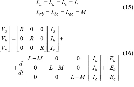
If the circuit is balance, the circuit of BLDC motor model has Eq. (14). This mathematical model using assumption that the magnet has high sensitivity and current induced of rotor can be neglected. It is also assumed that the stator resistances at all the windings are equal (R=Ra=Rb=Rc). Therefore the rotor reluctance does
not change with angle. Eq. (15) show the consequence of this assumption. Finally, the voltage equation become (16):
0 0
0 0
0 0
a a
b b
c c
a ba ca a a
ba b ca b b
ca ba c c c
V R I
V R I
V R I
L L L I E
d
L L L I E
dt
L L L I E
Bambang Sujanarko, Bambang Sri Kaloko, Moh. Hasan
Copyright © 2013 Praise Worthy Prize S.r.l. - All rights reserved International Review on Modelling and Simulations, Vol. 6, N. 6
a b c
ab bc ac
L L L L
L L L M
(15)
0 0
0 0
0 0
0 0
0 0
0 0
a a
b b
c c
a a
b b
c c
V R I
V R I
V R I
L M I E
d
L M I E
dt
L M I E
(16)
III.2. Torque and Speed Modelling
Fig. 5 shows a cutaway view of a BLDC.motor. This motor is a three-phase, 4-pole, 12-slot, full-pitch, surface mounted permanent magnet, trapezoidal Back EMF BLDC.
Fig. 5. Cutaway of BLDC motor
To drive the maximum torque/ampere motor, it is desired that the line current pulses be overlapped by the line-neutral Back EMF voltages of the particular phase.
This allows a maximum torque output by the fundamental physical principle of torque generation, i.e., Torque = Total Force × Moment Arm, where the force is produced by the interaction of the flux produced by the rotor magnets and the current in the stator coil sides.
From the Lorentz force equation is (17) [1]:
1coil side L t x
Force
N IB dl (17)In the running condition, two phases are excited with DC current in the same direction, and a radially magnetized magnet in the certain polarity was appeared overlap at two adjacent slots.
The flux magnetic in these part then force rotor to rotate. The total force is the sum of the forces of all of the active poles.
In a BLDC with radially magnetized magnets and full-pitched windings, the number of stator slots = (number of phases)×(number of poles). There are two phases simultaneously active with square wave excitation and in the magnet distance approximately equal to the pole arc, the electric torque (Te) is given as (18) [1].
The most accurate static torque for a specific machine geometry is determined by using a finite element software package that uses numerical methods:
e p t spp r x x
T N N N P I B L R (18)
This torque is equal to the peak or maximum torque, which can also be calculated by the load torque, torque due to inertia, the torque required to overcome the friction, the windage loss which is contributed by the resistance offered by the air in the air gap ant others. Eq. (19) shows the relation of these factors with k caused unknown factors [10].
In the dynamic model or if current supply of BLDC cause motor rotates in angular velocity, this torque also can be represented using equation (20) [9]. In this equation k is a constant.
Equation (19) can be modified using angular velocityas shown in
e L J F
T T T T k (19)
a a b b c c e
E I E I E I
T k
(20)
e L
d
T T J B k
dt
(21)
III.3. Speed Regulating Using PWM
Subtitute Eq. (18) to (20) and using assumption the current and Back EMF in three windings are in balance and using consideration that E is proportional to supply voltage, the angular speed of BLDC motor can can be arranged into (22). If V produce from voltage supply (Vs)
using PWM method [11], [12] as illustrated in Fig. 6, the voltage (V) can calculate using (23). Finally, if (23) substituted to (22), angular velocity become (24):
3
p t spp r
EI
k kE kV
N N N P I B L R
(22)
s
V DV (23)
s
kDV
(24)
PWM circuit build using compare a triangle wave and variable DC signal and then implemented to trigger signal by using AND digital logic [8].
Fig. 6. PWM signal
Copy separated proble specia MAT build Simuli Simuli const among runni start Simuli Tim capabi autom source appli 7 shows com real interfacing bus processor addresses L is analog [15]. Simuli (DI) opyrigh The separated problem This special MATLA build Simulink. Simulink constitue among running start and Simulink Time Worksho capabilitie automatic source co applicatio shows Using communi real equip interfac bus for The process address L is a type
This analog [15].
Refer Simulink
In th (DI) com
right ©
IV.
The mo eparated
roblem in This pro pecial MATLAB/
a dy Simulink. Simulink constitue among the
nning th tart and s Simulink can
ime Work capabilities automatical ource cod application shows RT Using communicat real equipmen terfacing for attach The d rocessor addresses is a type o
This PCI analog out
Refer sect Simulink can
n this I) compo
t © 201
IV.
he modeli rated field blem in pract
his problem ial hard MATLAB/Simu
a dyna link. Fir link mod titue time g the in
the and stop link can e Worksh
bilities omatically
ce code fro cations.
ws RTW
Fig
sing Ex munication equipment rfacing compo
for attachi he devices essor dire esses of the a type of PCI
his PCI h g output
V.
efer section link can b
is pict compone
2013 Pra
IV. M
odeling fields practice, re problem hardware B/Simuli dynamic First, nk model
time-the inpu
the Simu d stop co nk can be orkshop ties of ically gen ode from ions. The RTW cod
Fig. 7
Extern nication o equipment th ng compo
ttaching evices
directl of the ype of PCI t
PCI have outputs, 1
V.
section nk can buil
picture ponent o
3 Praise
Matlab/
deling, simu fields. The
practice, res roblem can
ardware Simulink mic sys First, cre odel edi
-depen e inputs,
Simulin op comman can be imp
rkshop (RT of ly generat e from Simu
The cod RTW code g
7. RTW
External cation on a
throug compone aching hardware
ices in PCI directly t
f the proce e of PCI that PCI have 16
puts, 16 a
The
ection II.3 can build as
icture, Hal nent of R
raise Wo
Matlab
simulation The deep practice, research oblem can hardware and
ulink envir ic system
creating del editor,
dependent nputs, model
imulink command be implem (RTW
of MA
generate from Simulink
he code code generati
RTW co
xternal m n on a real through an
ponents hardware in PCI ctly to
processor's CI that used have 16 digita s, 16 analog
The P
n II.3 and build as show
Hall nt of RTW.
Worthy
Matlab/Simulink
simulation The deep actice, research
can be are and ulink environm system creating editor, dependent model ulink model
mand [13] implemen
(RTW). MATLAB generates, packa
Simulink code generate code generati
TW code g
External mode a real-through an i
ponents is P hardware d n PCI slot ctly to the
processor's that used 16 digita 16 analog
The Prop
II.3 and III. as show Hall sensor of RTW.
rthy Prize
Matlab/Simu
ulation a deep gap esearch and
be bridge and nvironment tem there ating a blo editor, in dependent m
model model and [13] lemented TW). R MATLAB
s, package ulink mode generates eneration code gene mode -time h an interfa ts is PCI. hardware device
CI slot w to the proce
essor's addre t used in this
digital o analog input
The Propose
3 and III.3, shown in ll sensors TW. The
Bambang
Prize S.r
atlab/Simulink
tion and eep gap
arch and edu e bridged and sof
ironment there is g a bloc in the nt mathem
and odel in [13]. Sim
ented in RTW TLAB/ packages, ink models enerates ration proc e generatio
ode, the time, be an interfaci is PCI. PC re devices
slot will the processor or's address
ed in this ital outpu log input
e Proposed
d III.3, con own in Fig. sensors con
The DI
Bamb
ze S.r.l.
imulink
n and the gap amo and educat ridged th
software ment. In ere is two a block
n the grap mathemat
and out el in the Simul ted in real
TW /Simu ackages, co
models to erates in
roces
neration pro
, the between terfacing PCI. PCI evices in a t will be
processo address s in this res utputs, input and
roposed Con
III.3, contro in Fig. ors conn he DI sho
Bambang
.l. - All rig
/Simulink and PC
d the real among d educati ged throu software
n this two-lock diagra the graphi athematical d output n the cer Simulation in real ti
is an Simulink ackages, comp
models to real C lang rocess. tion process the between rfacing com I. PCI is a
in a will be
cessor b ress space is research. tputs, 16 put and 3
oposed Contr
III.3, control 8. connect DI should
ang Su
All rights
ulink and P
he real pl mong thes
ducation. ed through
tware d this env -step k diagram
graphical matical outputs. he certain
ulation ci real time,
is an ex mulink , compiles s to real
languag .
process [13
he system etween Simu ing compo
is a lo in a comp be conn ssor bus
s space research.
ts, 16 digi and 3 chan
d Control
control mod
connect to should be
g Sujan
rights re
k and PCI
real plant ng these cation. hrough th ware direct
his environme step proces diagram raphical form hematical relat
puts. The certain ation circ real time, us an exte link th compiles
real-time language
ess [13]
system en Simul component
local computer connected bus in
[14]. arch. 16 digital 3 channel
ontrol
rol modell
ct to Dig be prec
Sujanarko
ts reserv
and PCI
real plant are these beco
gh the us directly environm ep proces usin hical form al relatio
s. The tain time on circuit e, using extensi k that
and time so anguage [13 stem Simulink ponent. On local comp mputer. nnected
in as [14]. PCI1
digital inpu channels
ontrol
odelling
to Digital be preced
anarko,
erved
plant are t hese become
the use directly environment,
process w using ical form
relationsh The seco time usi circuit in
using Real extension
that and buil
softw guage [13]. F
enables ulink and ponent. One comput
. connected to
assigne 14]. PCI1711
ital inputs, hannels Tim
odelling using
Digital Inpu be preceded
, Bam
are three become a
the use of ectly in nment, to cess with sing the and tionships second, using uit in the Real nsion of that can and builds
software [13]. Fig.
enables ulink and a ponent. One of computer
d to the assigned PCI1711
inputs, 2 ls Timer
ng using
igital Input ceded by
Bambang
1903 hree me a
use of ectly in ent, to with g the and ships econd, using in the Real-n of
can builds ftware ]. Fig.
nables and a One of puter
the igned I1711
puts, 2 Timer
using
Digital Input ed by bang S 1903 set lev ( to w in fro op ex sig co [1 in in an res PW tak Si Si
ng Sri Ka
settin levels (DO to Q wirin Tri invert Th from optoc experi signa corres [12] invert invert and Fi research. PWM So taken Simu Th Simu Sri Kal Inte setting levels. DO), wh to Q6 to
wiring bo
Trigger inverter ci
This ci from th optocoup experien signals correspo [12] the inverter. inverter, and Fig. research. PWM freq
Some taken b Simulink
VI.1
The f Simulink Kaloko Interna the The ), which
to the ring board
Trigger s verter circu
This circu the tocoupler periencing
which rrespondin
the sign verter. Fig verter, wh d Fig. 1
earch. So M frequency an Some of aken by t
ulink.
VI.1.
The first ulink co
Kaloko, M
rnation
the chan The same , which us
to the dri board PCL
Fig
gger sign er circuit, wi is circuit
invert ouplers eriencing th
which h ponding t he signal
Fig. er, while Fig. 11 sh earch. Some
frequency me of th
by tool
VI.
VI.1.
irst con ink contro
Moh.
tional Re
the channel he same
used the driver board PCLD
Fig. 8.
Trigger signals circuit, will circuit must
inverter. and ncing the for
hich had onding to
signals then Fig. 9 show
while Fig. shows Some varia requency and of these by toolboxe
VI.
Simulin
irst control nk control m
oh. Hasan
l Review
channels same settin
used to conn driver ci board PCLD 8710
. Cont
ignals from it, will be it must ha verter. T
and sepa the form hich had dv/
specific s then
shows hile Fig.
shows photogra ome variabl
ncy and duty these m toolboxes
Resu
Simulink
control test trol model
h. Hasan
view on
nnels used, setting ed to conne iver circuit. LD 8710A
Control m
als from will be ente must hav rter. Theref
nd separat e formation ad dv/dt,
specificat s then enter
shows sche Fig. 10
ws photo variables and duty ese measure boxes in
Result a
ulink Cont
control testing l model.
asan
on Mo
els used, setting al
o connect r circuit. LD 8710AI.
ntrol mode
from the ll be entered
st have the r. Therefore
separate ormation dv/dt, di/d pecification enter ows schem show hows photogra
es such nd duty cy
measurem in the
Result an
k Contr
ol testing .
Modelli
used, time ing also connect the
rcuit. Thes 10AI.
l modelling
m the DO, be entered t
ave the a Therefore, eparate vo
ation in t, di/dt an fication o
entered schematic
shows ex otograph
es such as uty cycle, m easuremen
in the
sult and
k Control Mod
esting is
delling a
d, time ng also nee
nect the tri These
delling usin
the DO, e entered to dri
e the abili refore, the rate volt
in the i/dt and a ation of
ed to po chematic of
hows experi graph experi such as vo y cycle, meas
rements the sink
ult and Dis
rol Mod
g is veri
ng and S
time samp need fo the trigger
hese con
ing using S
DO, befo red to driver
e ability re, the d e voltage
the dri dt and amp
n of the p to power matic of the
s experimen ph experi h as voltage,
le, measu ents and
sink
ult and Discus
Model
verify
nd Simu
samplin need for e trigger o ese connec
sing Simu
DO, before ver ci bility to i
the driver voltage s
he driver d amplitud
the pow o power c of the dr experimen experimen as voltage, e, measured ts and fi grou
and Discuss
del Ver
erify the
imulatio
sampling d for Digital rigger outp
connection
Simulink
before enter circuit ty to isola e driver oltage supp
driver circui mplitude he power
ower device the driver experiment setu
eriment setup oltage, curren
ed and and figur
group
Discussion
Verificat
verify the log
lations, V
ling and Digital trigger output
connection th
ulink
efore enter circuit. to isolate driver circ
supplies driver circuit plitude volt power devi
er device the driver cir ent setup ent setup oltage, current
ed and captu d figures, group of
iscussion
Verification
the logic
ns, Vol.
and voltag Digital O utput signa onnection through
enter to . solate the driver circuit
ies. circuit, trigg
voltage devices device gate driver circuit ent setup sche
t setup current, R and capture gures, will of Matl
ication
logic trut
ol. 6, N
and voltag gital Outp
signal Q n through
nter to the
te the PC circuit u
. After cuit, trigge
voltage tha evices use ice gate r circuit an
schem etup in th rrent, RPM d captured es, will b of Matlab/
ion
ic truth
6, N. 6
voltage Output ignal Q1
hrough a
r to the
the PCI uit use . After , trigger age that used gate of cuit and scheme
in this t, RPM, aptured.
will be Matlab/
truth of
N. 6
ltage utput
1
gh a
the PCI e After rigger age that used te of t and eme this RPM,
ll be atlab/
Copy and motor value bit val So has Lo opyrigh Fig. 1 This and DO motor and These values Com bit value So it can has been
Perso
Load
right ©
Fig. 12 This figu and DO. D motor and D
These b s as sh ompari it values
it can b as been
Cont using P
Persona
Load
t © 201
2 the his figure DO. DI are
r and DO are hese bit
as shown omparison
s in th can be been mad
Control Mo using Sim PCI 17 card ersonal Co 2013 Pra Fig Fig Fig the resu figure find are r and DO are b
bits con s shown i mparison bet
in the t n be concl n made
ntrol Mod ing Simulin
CI 1711 L card nal Comp Gen 3 Praise Fig. 9 Fig. 10 Fig. 1 result o find from repres O are b
condi hown in Tab
between n the tabl
conclud ade cor l Model imulink 711 L Computer DC Generat raise Wo 9. Driv 10. Ex 11. Ex
result of this from represent are bit cond
condition n in Table
between he table show concluded correctly puter DC Generator Worthy Driver a Experim Experim
result of this tes from scop represent three
it condition tion m in Table I
etween bit show d tha correctly
rthy Prize
Driver and In
xperimen
xperimen
f this testing from scope
esent three condition tion must
I. bit va show that
that the ectly and
Bambang
Prize S.r
r and Invert
riment setu
riment setu
is testing scope toll t three Hall ndition of ion must be
value ow that th that the ly and
PC 87
Dri
Bamb
ze S.r.l.
d Inverter c
ent setup sc
ent setup sc
esting in t pe toll bo Hall s ion of trig must be s
values that these Simu acco PCLD 8710 A Driver Invert BLDC Moto Bambang
.l. - All rig
erter circu
setup schem
setup schem
in the C oll box Hall senso
trigger be simil
from hat these val
Simulink accordance PCLD 710 AI river and Inverter BLDC Motor ang Su All rights r circuit scheme scheme
in the CC that co ll sensor triggers similar
from the ese values imulink cordance r and g Sujan rights re CW that conn nsors in t
(Q1 milar wit
the pi e values are
cont dance to
Sujanarko
ts reserv
W direct hat connec
in the BL (Q1-Q6) ar with t
the pictu alues are s control ance to step
anarko,
erved
direction connect to
in the BLDC Q6). with trigge
the picture ues are simila
control mod step Hall Senso signa , Bam direction. ect to DI he BLDC
ith trigger
picture and are similar.
ol model step six
Hall Sensor signal Bambang . to DI LDC rigger and milar. model six bang S pri Si of in cy du on al do of co co th
ng Sri Ka
princi
Th Simu of th invert On cycle duty on sta alway done of PWM control control Th the si Sri Kal Inte principle Fig.
The s Simulonk of this inverter o
On st cycle val duty cycl on state always i done deep of PWM control mo control o
This s simu
Kaloko
Interna
nciple. Th
Fig. 12
The seco ulonk co this test verter or o
Fig.
On state cle value. ty cycle i state is wi
ays in th ne deeply
PWM si ntrol mod ntrol of BL
VI.2
This sect simulink
Kaloko, M
rnation
This v
2. Logi
e second onk contro is testing
er or only
Fig. 13.
state (T
value. In ycle is smal
is widt s in the h deeply in M signal rol model rol of BLD
VI.2.
is section ulink co
Moh.
tional Re
This verific
Logic of
second contro nk control
testing. In nly Q4,
Logic
Ton)
alue. In this cle is small, is width. If in the high eeply in [12].
signals. odel has of BLDC m
VI.2. U
section presen ulink contro
oh. Hasan
l Review
is verificatio
gic of Simu
d control ntrol using testing. In this
Q4, Q
Logic of S
) of In this ex small, on width. If duty
e high state. deeply in [12]. F
signals. Abov odel has been DC motor.
Using for
on presents k control
h. Hasan
view on
erification
of Simulin
ontrol testing ol using P In this Q4, Q5 and
ic of Simu
) of this his example
all, on state h. If duty
igh state. [12]. Fig
Above as been
motor. sing Sim for M presents ntrol model asan on Mo ification imulink co
trol testin sing PW this res , Q5 and Q
f Simulink
of this PWM example, l, on state If duty cycle
state. The ]. Figs.
Above testin been made otor.
Using Simulink for Motor
esents the model
Modelli
has b
link contro
testing is g PWM. is research 5 and Q6 t
ulink con
his PWM ample, the
state is n ty cycle i ate. These
14 ove testing en made
imulink Motor Res
the res to ob
delling a
has been
control mo
ting is veri WM. Fig research and Q6 that
link control
PWM is example, the du ate is narr cycle is 10 These veri
show testings made corr
link Co r Respo
he results obtain
ng and S
s been do
trol model
ng is verify . Fig. arch onl 6 that use PW
ontrol mod
M is dep the duty cy is narrow ycle is 100%,
verifi show os estings sh made correct
Contr Respon Tes
results of obtain th
nd Simu
done
odel in C
verify th 13 only bo hat use PWM.
l model us
PWM is depen e duty cycl
arrow but s 100%, o verificati oscill ngs show correctly a
ontrol on Test
ults of tes the ch
imulatio
done in
in CCW
verify the logic show only bottom that use PWM
model using P
depend on y cycle is
but if 00%, on state erifications
oscillosco show that ectly and
ol Model Testing testing the characte lations, V in [8]. W dire
y the logic shows th bottom use PWM.
using PW
epend on cycle is 50%
but if it is 00%, on state verifications ha oscilloscope how that S ectly and can
Model sting testing characte ns, Vol. 8]. direction
e logic t shows the res
bottom part
g PWM
d on the cycle is 50%.
but if it is big, n state beco ons have oscope captu
that Sim and can use
Model
the us aracteristic
ol. 6, N
rection
logic truth ows the result
tom part
on the dut 50%. If the it is big, the tate becom
have bee ope captur at Simulink
can use
the use acteristics
6, N. 6
th of he result part of
he duty 0%. If the big, the become ve been capture Simulink n use as
e use of ristics of
N. 6
th of result rt of
duty If the , the come been pture ulink e as
use of of
Bambang Sujanarko, Bambang Sri Kaloko, Moh. Hasan
Copyright © 2013 Praise Worthy Prize S.r.l. - All rights reserved International Review on Modelling and Simulations, Vol. 6, N. 6
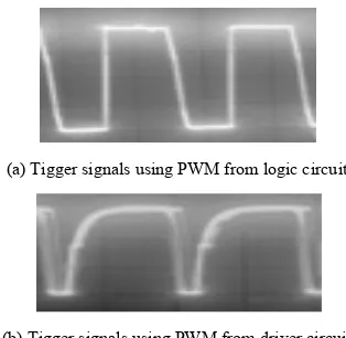
1905 BLDC motor on duty cycle variation of PWM and frequency.
(a) Tigger signals using PWM from logic circuit
(b) Tigger signals using PWM from driver circuit
Figs. 14. PWM signals [12]
Duty cycle variation can make by fill DC box of control with number 0 to 5, which denote duty cycle in 0 to 100%, while the frequency of PWM can be varied using time determination of sawtooth generator of simulink control model.
This testing use BLDC motor that have nominal power 500 W, rotation speed 500 rpm and 48 V power supply voltage. But in this testing the power supply used in 12 V.
Fig. 15 shows speed responds in this testing on duty cycle variation, while Figs. 16 and 17 show voltage and current responds.
Fig. 15. Speed responds on duty cycle
Fig. 16. Voltage responds on duty cycle
Fig. 17. Current responds on duty cycle
Fig. 18. Speed responds on frequency
Fig. 19. Voltage responds on frequency
Fig. 20. Current responds on frequency
Bambang Sujanarko, Bambang Sri Kaloko, Moh. Hasan
Copyright © 2013 Praise Worthy Prize S.r.l. - All rights reserved International Review on Modelling and Simulations, Vol. 6, N. 6
variable considered in ideal condition. But voltage responds is linear as defined in (23). Non linear correlation also happen on current responds. The non linear function occurred if duty cycle in the duty cycle above of 70%.
These phenomena can be explained using (21), where there is dependency on mechanical properties among speed, load, friction, inertia and electric torque.
Usually BLDC motor use PWM frequency above 6 kHz [10], but since the PCI only has the ability to transfer data at 10 kHz, so in this research the highest PWM frequency is 800 Hz. This frequency obtained from trial and error, wherein the frequency able to give a good shape of PWM. The highest PWM frequency has been used in the duty cycle variation as discussed previously. In the following sections present BLDC motor responds in the PWM frequency variation at 60% duty cycle, particularly to obtain the speed responds, voltage and current of motor.
Figs. 18 and 19 show speed responds and voltage responds of PWM frequency variations. The responds indicate that there is no influence of the PWM frequency to the motor speed and voltage. While for the current responds as shown in Fig. 20, there are non linear correlations, like occurred on the variation of duty cycle.
VII. Conclusion
This research has successfully made BLDC motor control using Matlab Simulink, and the interface to the actual hardware using PCI. Control models constructed using simulink element, and this model also can be used as a real control through the RTW facilities used. The experiment results show that the control can be used to control the BLDCmotor, and can generate an appropriate responds within the electrical and mechanical models.
The results of this research are very useful for BLDC motor control modeling and the real testing, easily, quickly and efficiently. It can be helped to generated a better of BLDC motor control.
Acknowledgements
This work was supported by research grant - Riset Unggulan Universitas Jember dana BOPTN, Kementrian Pendidikan dan Kebudayaan Republik Indonesia.
References
[1] Ali Emadi, Handbook of Automotive Power Electronics and Motor Drives (Taylor & Francis Group, CRC Press, 2005). [2] Padmaraja Yedamale, Brushless DC (BLDC) Motor
Fundamentals (Microchip Technology Inc., 2003)
[3] Sathyan, A. ; Milivojevic, N. ; Young-Joo Lee ; Krishnamurthy, M. ; Emadi, A., An FPGA-Based Novel Digital PWM Control Scheme for BLDC Motor Drives, Industrial Electronics, IEEE Transactions on, Vol.: 56 , Issue: 8, 2009, pp.: 3040 - 3049. [4] Matsui, N. ; Ohashi, H., DSP-Based Adaptive Control of A
Brushless Motor, Industry Applications, IEEE Transactions on,Volume: 28 , Issue: 2, 1992 , Page(s): 448 – 454.
[5] Semiconductor Components Industries, MC33035 NCV33035 Brushless DC Motor Controller- Publication Order (On Semiconductor, 2006).
[6] Atmel Corporation, AVR498: Sensorless control of BLDC Motors using ATtiny261/461/861-Application Note (Atmel Corporation, 2009).
[7] Stan D’Souza, AN957 Sensored BLDC Motor Control Using dsPIC30F2010-Application Notes (Microchip Technology, 2004).
[8] Bambang Sujanarko, Brushless Direct Current (Bldc) Motor Controller Using Digital Logic For Electric Vehicle, National Conference ReTII ke-7 Tahun 2012, STTNAS Yogyakarta, 2012. [9] Caner, M., Gerada, C., Asher, G., Permanent magnet motor
design optimisation for sensorless control, (2013) International Review of Electrical Engineering (IREE), 8 (1), pp. 172-181. [10] Padmaraja Yedamale, AN885 Brushless DC (BLDC) Motor
Fundamentals, Application Notes (Microchip Technology, 2003). [11] Mirzaei, H., Pahlavani, M.A., Naderi, P., Comparison of direct torque control of BLDC motor with minimum torque ripple in four and six-switch inverters, (2013) International Review of Electrical Engineering (IREE), 8 (3), pp. 971-980.
[12] Bambang Sujanarko, Desain Kontrol PWM Pengatur Kecepatan Motor BLDC Untuk Mobil Listrik, National Conference Semantik Tahun 2013, UDINUS Semarang, 2013.
[13] The MathWorks, Matlab (The MathWorks, Inc., 2013).
[14] Loeb, M.L. ; Rindos, A.J. ; Holland, W.G. ; Woolet, S.P., Gigabit Ethernet PCI adapter performance, Network, IEEE, Vol. 15, Issue: 2, 2001, pp. 42 – 47.
[15] Advantech, PCI-1711/L Entry-level 100 kS/s, 12-bit, 16-ch PCI Multifunction Card (Advantech).
Authors’ information
1Jurusan Teknik Elektro, Fakultas Teknik, Universitas Jember. 2
Jurusan Matematika, Fakultas MIPA, Universitas Jember.
Bambang Sujanarko received the B.Sc from
Universitas Gadjah Mada, Yogyakarta Indonesia, Master from Universitas Jember, Indonesia and Doctor fron Institut Teknologi Sepeluh Nopember (ITS) Surabaya, Indonesia. He is senior lecture of Departement Electrical, Engineering Faculty, Universitas Jember. His research interests included power electronics and renewable energy systems, hybrid power systems, artificial intelligent, electric vehicle and instrumentation.
Bambang Sri Kaloko received the B.Sc and
Master from Institur Teknologi Bandung, Indonesia and Doctor fron Institut Teknologi Sepeluh Nopember (ITS) Surabaya, Indonesia. He is lecture of Departement Electrical, Engineering Faculty, Universitas Jember. His research interests included power analysis, battery system, renewable energy systems, artificial intelligent and electric vehicle.
Moh. Hasan received the B.Sc form
Universitas Jember, Master from The University of Western Australia, Perth Australia and Doctor fron Wageningen University, Wageningen Holland. He is senior lecture of Departement Math, Math and Science Faculty, Universitas Jember. Now, he is rector of University of Jember. His research interests included modelling of nature phenomena.
International Review on Modelling and Simulations
(IREMOS)
(continued from outside front cover)
An Adaptive Hysteresis Band Current Controller Based DSTATCOM for E nhancement of Power Quality with Various Load
by J. Ramesh, T. A ruldoss A lbert V ictoire
1814
A Multi-Objective Contingency Constrained Optimal Power F low Based on Composite Security Index Using Genetic Algorithm and Newton Method
by R. Sunitha, R. Sreerama Kumar, A braham T. Mathew
1821
Voltage Constrained Maximum Loadability Analysisin Power System Using F ACTS by A . A nbarasan, M. Y. Sanavullah, S. Ramesh
1831
Non-Iterative Optimization Algorithm Based D-STATCOM for Power Quality E nhancement by S. Premalatha, Subhransu Sek har Dash, J. A run V enk atesh, N. K. Rayaguru
1837
PV Supported DVR and D-STATCOM for Mitigating Power Quality Issues by S. Premalatha, Subhransu Sek har Dash, D. Sunitha, R. Mohanasundaram
1849
Open and Short Circuit Diagnosis of a VSI F ed Three Phase Induction Motor Drive Using F uzzy Logic Technique
by K. Mohanraj, S. Paramasivam, Subhranshu Sek har Dash, A . F. Zobaa
1858
A Comparative Study of IP, F uzzy Logic and Sliding Mode Controllers in a Speed Vector Control of Induction Motor
by A . Bennassar, A . A bbou, M. A k herraz, M. Barara
1865
PI and F uzzy Hysteresis Current Controlled Inverter for PMSM Based E Vs Drives by F. Grouz, L . Sbita
1872
Use of the Short Time F ourier Transform for Induction Motor Broken Bars Detection by Fethi A . A imer, A hmed H. Boudinar, A zeddine Bendiabdellah
1879
Diagnosis of Stator Winding Short Circuit F ault in Three Phase Squirrel Cage Induction Machine by K. Deepa, P. V anaja Ranjan, S. Deepa
1884
Improved Genetic Algorithm Identification of the Squirrel-Cage Induction Machine Parameters by Mohamed Moutchou, Hassan Mahmoudi
1891
BLDC Motor Control Using Simulink Matlab and PCI by Bambang Sujanark o, Bambang Sri Kalok o, Moh. Hasan
1899
Analysis of DC Bus F ault and Line F aults on Voltage Source Inverter F ed Induction Motor by K. Mohanraj, S. Paramasivam, Subhransu Sek har Dash, S. Ramprasad
1907
A Novel Approach for an E nhanced High F requency Single Stage Matrix Converter for Induction Heating Application
by P. Umasank ar, S. Senthilk umar
1914
(continued on Part B)
Abstracting and Indexing Information:
Academic Search Complete - EBSCO Information Services Cambridge Scientific Abstracts - CSA/CIG
Elsevier Bibliographic Database SCOPUS
Index Copernicus (Journal Master List): Impact Factor 6.55
Autorizzazione del Tribunale di Napoli n. 78 del 1/10/2008
This volume cannot be sold separately by Part B